technical specifications FIAT QUBO 2008 1.G Workshop Manual
[x] Cancel search | Manufacturer: FIAT, Model Year: 2008, Model line: QUBO, Model: FIAT QUBO 2008 1.GPages: 202, PDF Size: 3.43 MB
Page 55 of 202

54
SAFETY
STARTING
AND DRIVING
WARNING
LIGHTS AND
MESSAGES
IN AN
EMERGENCY
MAINTENANCE
AND CARE
TECHNICAL
SPECIFICATIONS
INDEX
DASHBOARD
AND CONTROLS
CONTROLS
EMERGENCY LIGHTS
Emergency lights switch on by pressing
switch A-fig. 49, regardless of the posi-
tion of the ignition key.
When the device is on warning lights
Îand ¥on the panel come on.
Press switch Aagain to turn the lights off.
IMPORTANT The use of emergency lights
is governed by the Highway Code of the
country where you are driving. Keep to
the rules.
Emergency braking
(where present)
In the case of emergency braking the haz-
ard warning lights come on automatically
and the warning lights
Îand ¥in the
panel light up at the same time. The func-
tion is switched off automatically when the
nature of the braking is no longer an emer-
gency. This function complies with the leg-
islation currently in force.FOG LIGHTS
(where provided) fig. 50
To turn front fog lights on, press button
5. To activate these lights it is necessary
to have the side/taillights switched on.
The warning light switches on
5on the
instrument panel.
Press the button again to turn the lights
off.REAR FOG LIGHTS fig. 50
The rear fog lights switch on, with low
beams or front fog lights on, by pressing
the button 4.
The warning light switches on 4on the
instrument panel.
Press the button again or switch off the
dipped beams and/or front fog lights
(where provided) to turn the rear fog
lights off.
fig. 49
A
F0T0049mfig. 50F0T0036m
036-082 Fiorino GB 1ed 21-10-2008 14:58 Pagina 54
Page 56 of 202
55
SAFETY
STARTING
AND DRIVING
WARNING
LIGHTS AND
MESSAGES
IN AN
EMERGENCY
MAINTENANCE
AND CARE
TECHNICAL
SPECIFICATIONS
INDEX
DASHBOARD
AND CONTROLS
FUEL CUT-OFF SYSTEM
This system triggers after a collision and
activates the following:
❒switch off of fuel supply with conse-
quent engine switch off;
❒automatic door unlocking;
❒switch on of all lights inside the vehicle.
When the system is triggered, the mes-
sage “Fuel cut-off tripped - see handbook”
is displayed on some versions.
Carefully check the vehicle for fuel leaks,
for instance in the engine compartment
below the vehicle or near the fuel tank
area.
After the collision, position ignition key on
STOPto avoid battery draining.To reset vehicle operation, follow this
procedure:
❒turn the ignition key to MAR;
❒activate the right-hand indicator;
❒deactivate the right-hand indicator;
❒activate the left-hand indicator;
❒deactivate the left-hand indicator;
❒activate the right-hand indicator;
❒deactivate the right-hand indicator;
❒activate the left-hand indicator;
❒deactivate the left-hand indicator;
❒turn the ignition key to STOP.
If, after a crash, you smell fu-
el or notice leaks from the
fuel system, do not reset the system
to avoid fire risk.
WARNING
036-082 Fiorino GB 1ed 21-10-2008 14:58 Pagina 55
Page 57 of 202

56
SAFETY
STARTING
AND DRIVING
WARNING
LIGHTS AND
MESSAGES
IN AN
EMERGENCY
MAINTENANCE
AND CARE
TECHNICAL
SPECIFICATIONS
INDEX
DASHBOARD
AND CONTROLS
INTERIOR FITTINGS
ARMREST ON DRIVER’S SEAT
(where provided) fig. 51
In some versions the front seat on the dri-
ver’s side is supplied with an armrest.
The armrest is lowered/lifted as illustrat-
ed by the arrows.
ODDMENT
COMPARTMENT fig. 52
The oddment compartment is positioned
opposite the front seat on the passenger’s
side.GLOVE BOX (where provided)
To open the glove box pull the handle
A-fig. 53.
fig. 51F0T0056m
fig. 52F0T0187m
fig. 53F0T0069m
Do not travel with the glove
box open: the passenger may
get hurt in the event of a crash.
WARNING
036-082 Fiorino GB 1ed 21-10-2008 14:58 Pagina 56
Page 58 of 202
57
SAFETY
STARTING
AND DRIVING
WARNING
LIGHTS AND
MESSAGES
IN AN
EMERGENCY
MAINTENANCE
AND CARE
TECHNICAL
SPECIFICATIONS
INDEX
DASHBOARD
AND CONTROLS
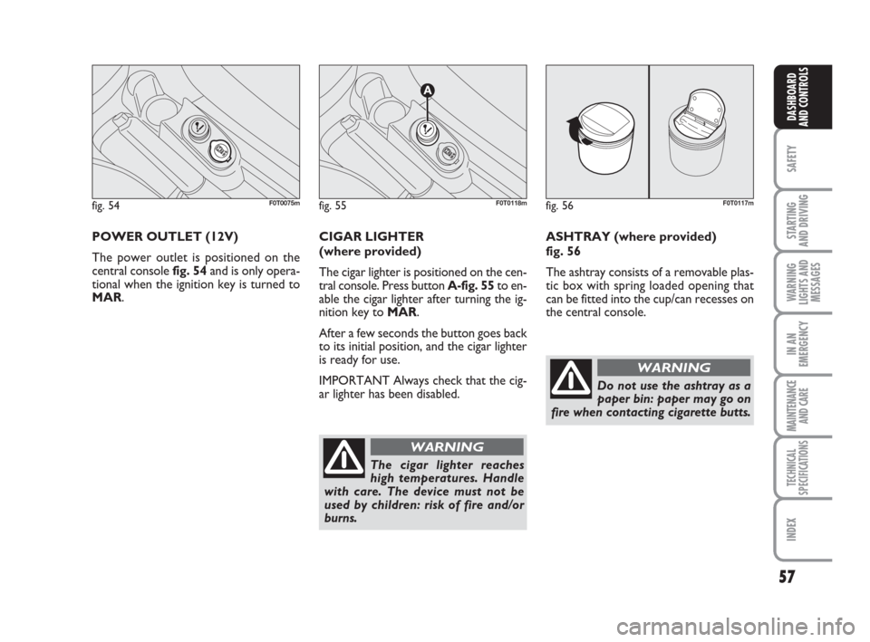
POWER OUTLET (12V)
The power outlet is positioned on the
central console fig. 54and is only opera-
tional when the ignition key is turned to
MAR. CIGAR LIGHTER
(where provided)
The cigar lighter is positioned on the cen-
tral console. Press button A-fig. 55to en-
able the cigar lighter after turning the ig-
nition key to MAR.
After a few seconds the button goes back
to its initial position, and the cigar lighter
is ready for use.
IMPORTANT Always check that the cig-
ar lighter has been disabled.
fig. 54F0T0075mfig. 55
A
F0T0118m
The cigar lighter reaches
high temperatures. Handle
with care. The device must not be
used by children: risk of fire and/or
burns.
WARNING
fig. 56F0T0117m
ASHTRAY (where provided)
fig. 56
The ashtray consists of a removable plas-
tic box with spring loaded opening that
can be fitted into the cup/can recesses on
the central console.
Do not use the ashtray as a
paper bin: paper may go on
fire when contacting cigarette butts.
WARNING
036-082 Fiorino GB 1ed 21-10-2008 14:58 Pagina 57
Page 59 of 202

58
SAFETY
STARTING
AND DRIVING
WARNING
LIGHTS AND
MESSAGES
IN AN
EMERGENCY
MAINTENANCE
AND CARE
TECHNICAL
SPECIFICATIONS
INDEX
DASHBOARD
AND CONTROLS
fig. 59F0T0207m
fig. 60
A
F0T0135m
SUN VISORS fig. 57
The sun visors on the driver’s and pas-
senger’s sides are directable both frontal-
ly and sideways.
Behind the sun visor on the driver’s side
a pocket has been provided for storing
tickets.
Some vehicle versions feature the sun vi-
sor with a mirror on the passenger’s side.DESK (where provided)
In the middle of the dashboard above the
sound system compartment a desk
A-fig. 58has been provided. On some
versions this desk can be used as a read-
ing desk by lifting its back and placing it on
the dashboard as illustrated in the figure.
On versions equipped with an airbag on
the passenger’s side the desk is stationary.
fig. 57F0T0188m
REAR SIDE WINDOWS WITH
“COMPASS” OPENINGfig. 59
To open the rear side windows proceed
as follows:
❒move lever A-fig. 60outwards until
the window opens completely;
❒push the lever backwards until the win-
dow clicks in position.
To close the windows carry out the op-
erations above in reverse order until you
hear the click indicating correct lever po-
sitioning.
fig. 58F0T0204m
036-082 Fiorino GB 1ed 21-10-2008 14:58 Pagina 58
Page 60 of 202
59
SAFETY
STARTING
AND DRIVING
WARNING
LIGHTS AND
MESSAGES
IN AN
EMERGENCY
MAINTENANCE
AND CARE
TECHNICAL
SPECIFICATIONS
INDEX
DASHBOARD
AND CONTROLS
DOORS
CENTRAL DOOR
LOCKING/UNLOCKING SYSTEM
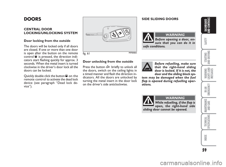
Door locking from the outside
The doors will be locked only if all doors
are closed. If one or more than one door
is open after the button on the remote
control
Øis pressed, the direction indi-
cators start flashing quickly for approx. 3
seconds. When the metal insert is turned
clockwise in the driver’s door lock all the
doors can be locked.
Quickly double click the button
Øon the
remote control
to activate the dead lock
device (see paragraph “Dead lock de-
vice”). Door unlocking from the outside
Press the button Æbriefly to unlock all
the doors, switch on the ceiling lights in
a timed manner and flash the direction in-
dicators. All the doors are unlocked by
turning the metal insert in the door lock
on the driver’s side anticlockwise.
fig. 61F0T0242m
While refuelling, if the flap is
open, the right-hand side
sliding door cannot be opened.
WARNING
SIDE SLIDING DOORS
Before opening a door, en-
sure that you can do it in
safe conditions.
WARNING
Before refuelling, make sure
that the right-hand sliding
door is locked. If it is not, the
door and the sliding block sys-
tem may be damaged when the fuel
flap is opened during refuelling oper-
ations.
036-082 Fiorino GB 1ed 21-10-2008 14:58 Pagina 59
Page 61 of 202
60
SAFETY
STARTING
AND DRIVING
WARNING
LIGHTS AND
MESSAGES
IN AN
EMERGENCY
MAINTENANCE
AND CARE
TECHNICAL
SPECIFICATIONS
INDEX
DASHBOARD
AND CONTROLS
fig. 64F0T0137m
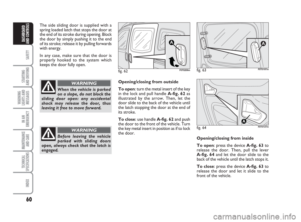
Opening/closing from outside
To open: turn the metal insert of the key
in the lock and pull handle A-fig. 62as
illustrated by the arrow. Then, let the
door slide to the back of the vehicle until
the latch stopping the door at the end of
its stroke.
To close: use handle A-fig. 62and push
the door to the front of the vehicle. Turn
the key metal insert in position as if to lock
the door.
fig. 62F0T0209m
When the vehicle is parked
on a slope, do not block the
sliding door open: any accidental
shock may release the door, thus
leaving it free to move forward.
WARNING
Before leaving the vehicle
parked with sliding doors
open, always check that the latch is
engaged.
WARNING
The side sliding door is supplied with a
spring loaded latch that stops the door at
the end of its stroke during opening. Block
the door by simply pushing it to the end
of its stroke; release it by pulling forwards
with energy.
In any case, make sure that the door is
properly hooked to the system which
keeps the door fully open.
fig. 63
A
F0T0197m
Opening/closing from inside
To open: press the device A-fig. 63to
release the door. Then, pull the lever
A-fig. 64and let the door slide to the
back of the vehicle until the latch stops it.
To close: press the device A-fig. 63to
release the door and let it slide to the
front of the vehicle.
036-082 Fiorino GB 1ed 21-10-2008 14:58 Pagina 60
Page 62 of 202
61
SAFETY
STARTING
AND DRIVING
WARNING
LIGHTS AND
MESSAGES
IN AN
EMERGENCY
MAINTENANCE
AND CARE
TECHNICAL
SPECIFICATIONS
INDEX
DASHBOARD
AND CONTROLS
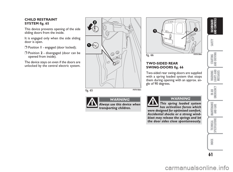
TWO-SIDED REAR
SWING-DOORS fig. 66
Two-sided rear swing-doors are supplied
with a spring loaded system that stops
them during opening with an approx. an-
gle of 90 degrees.
fig. 66F0T0139m
This spring loaded system
has activation forces which
were designed for optimised comfort.
Accidental shocks or a strong wind-
blast may release the springs and let
the door sides close spontaneously.
WARNING
fig. 65F0T0138m
Always use this device when
transporting children.
WARNING
CHILD RESTRAINT
SYSTEM fig. 65
This device prevents opening of the side
sliding doors from the inside.
It is engaged only when the side sliding
door is open.
❒Position 1- engaged (door locked);
❒Position 2- disengaged (door can be
opened from inside).
The device stays on even if the doors are
unlocked by the central electric system.
036-082 Fiorino GB 1ed 21-10-2008 14:58 Pagina 61
Page 63 of 202
62
SAFETY
STARTING
AND DRIVING
WARNING
LIGHTS AND
MESSAGES
IN AN
EMERGENCY
MAINTENANCE
AND CARE
TECHNICAL
SPECIFICATIONS
INDEX
DASHBOARD
AND CONTROLS
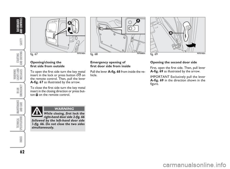
Emergency opening of
first door side from inside
Pull the lever A-fig. 68from inside the ve-
hicle.Opening the second door side
First, open the first side. Then, pull lever
A-fig. 69 as illustrated by the arrow.
IMPORTANT Exclusively pull the lever
A-fig. 69in the direction shown in the
figure.
fig. 68F0T0060mfig. 69F0T0142m
Opening/closing the
first side from outside
To open the first side turn the key metal
insert in the lock or press button ∞on
the remote control. Then, pull the lever
A-fig. 67as illustrated by the arrow.
To close the first side turn the key metal
insert in the closing direction or press but-
ton Áon the remote control.
fig. 67F0T0140m
While closing, first lock the
right-hand door side 2-fig. 66
followed by the left-hand door side
1-fig. 66. Do not close the two sides
simultaneously.
WARNING
036-082 Fiorino GB 1ed 21-10-2008 14:58 Pagina 62
Page 64 of 202
63
SAFETY
STARTING
AND DRIVING
WARNING
LIGHTS AND
MESSAGES
IN AN
EMERGENCY
MAINTENANCE
AND CARE
TECHNICAL
SPECIFICATIONS
INDEX
DASHBOARD
AND CONTROLS
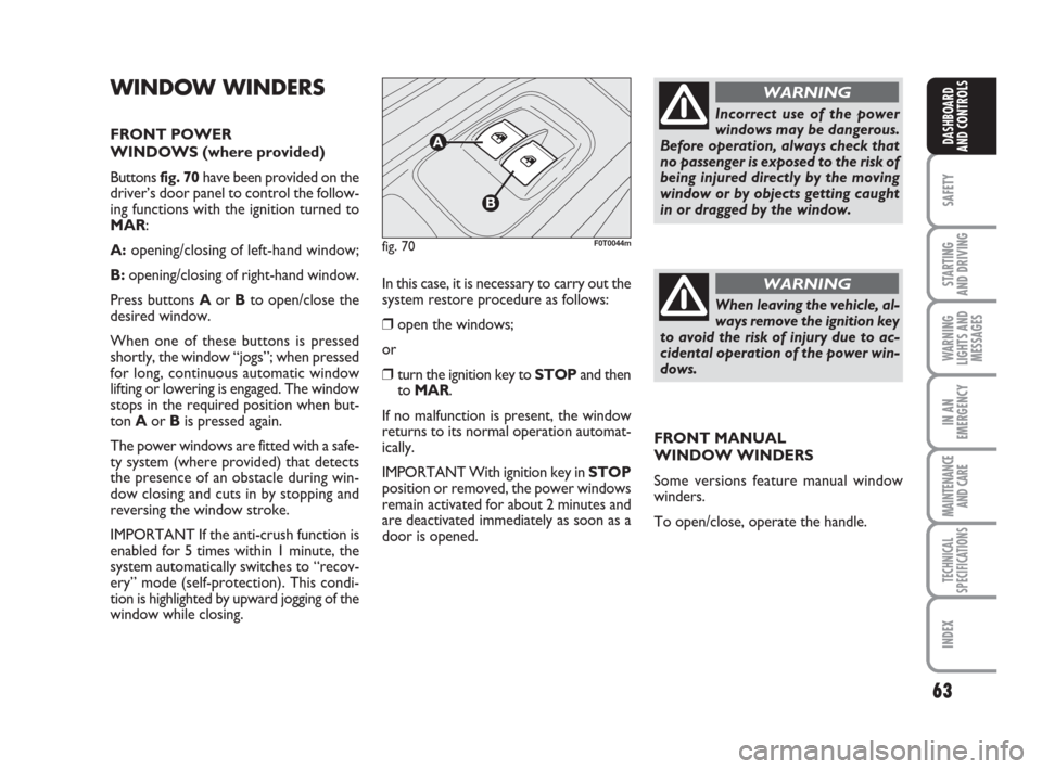
WINDOW WINDERS
FRONT POWER
WINDOWS (where provided)
Buttons fig. 70have been provided on the
driver’s door panel to control the follow-
ing functions with the ignition turned to
MAR:
A:opening/closing of left-hand window;
B:opening/closing of right-hand window.
Press buttons Aor Bto open/close the
desired window.
When one of these buttons is pressed
shortly, the window “jogs”; when pressed
for long, continuous automatic window
lifting or lowering is engaged. The window
stops in the required position when but-
ton Aor Bis pressed again.
The power windows are fitted with a safe-
ty system (where provided) that detects
the presence of an obstacle during win-
dow closing and cuts in by stopping and
reversing the window stroke.
IMPORTANT If the anti-crush function is
enabled for 5 times within 1 minute, the
system automatically switches to “recov-
ery” mode (self-protection). This condi-
tion is highlighted by upward jogging of the
window while closing.In this case, it is necessary to carry out the
system restore procedure as follows:
❒open the windows;
or
❒turn the ignition key to STOPand then
to MAR.
If no malfunction is present, the window
returns to its normal operation automat-
ically.
IMPORTANT With ignition key in STOP
position or removed, the power windows
remain activated for about 2 minutes and
are deactivated immediately as soon as a
door is opened.
fig. 70F0T0044m
Incorrect use of the power
windows may be dangerous.
Before operation, always check that
no passenger is exposed to the risk of
being injured directly by the moving
window or by objects getting caught
in or dragged by the window.
WARNING
When leaving the vehicle, al-
ways remove the ignition key
to avoid the risk of injury due to ac-
cidental operation of the power win-
dows.
WARNING
FRONT MANUAL
WINDOW WINDERS
Some versions feature manual window
winders.
To open/close, operate the handle.
036-082 Fiorino GB 1ed 21-10-2008 14:58 Pagina 63