display FIAT QUBO 2010 1.G Owner's Manual
[x] Cancel search | Manufacturer: FIAT, Model Year: 2010, Model line: QUBO, Model: FIAT QUBO 2010 1.GPages: 230, PDF Size: 4.38 MB
Page 76 of 230
ABS SYSTEM
This is an integral part of the braking system, which
prevents one or more wheels from locking or
slipping regardless of the road surface conditions and
braking intensity, giving the best control during
emergency braking.
The EBD system (Electronic Braking Force
Distribution) completes the system, allowing the
brake force to be distributed between the front and
rear wheels.
IMPORTANT For maximum efficiency of the braking
system, a bedding-in period of about 500 km is
needed: during this period it is better to avoid sharp,
repeated and prolonged braking.
SYSTEM INTERVENTION
The driver can tell the ABS system has come into
action because the brake pedal pulsates slightly and
the system gets noisier: it means that the vehicle
speed should be altered to suit the type of road
surface.
WARNING
When the ABS cuts in and you feel the
br
ake pedal pulsating, do not remove
your foot , but keep the pedal pushed down; in
doing so you, will stop in the shortest distance
possible under the road conditions at the time.
WARNING
If the ABS cuts in, it is a sign that the
gr
ip between tyre and the road surface
has reached the limit : you must slow down to
match the speed to the road grip available.
WARNING
The ABS gets the most from the
av
ailable grip, but it cannot improve it ;
you should therefore take every care when
driving on slippery surfaces and not take
unnecessary risks.
FAILURE INDICATIONS
ABS failure
ABS failure is indicated by warning light
in the
instrument panel coming on (together with the
appropriate message on the multifunction display on
some versions) (see “Warning lights and messages”).
In this case, the braking system will work as normal,
but without the extra capacity offered by the ABS
system. Drive carefully to the nearest Fiat Dealership
to have the system checked.
75
KNOW YOUR
VEHICLE
SAFETY
ST
ARTING AND
DRIVING
WARNING LIGHTS
AND MESSAGES
IN AN EMERGENCY
SERVICING AND
MAINTENANCE
TECHNICAL
SPECIFICATIONS
INDEX
Page 77 of 230
EBD failure
ABS failure is indicated by warning light
andin
the instrument panel coming on (together with the
appropriate message on the multifunction display
on some versions) (see “Warning lights and
messages”).
In this case, the rear wheels may suddenly lock and
the vehicle may swerve when braking sharply. Drive
carefully to the nearest Fiat Dealership to have
the system checked.
WARNING
If only warning lightlights up in the
instrument panel (with a message in the
multifunction display on some versions), stop
the vehicle immediately and contact the nearest
Fiat Dealership. Fluid leaking from the
hydraulic system will compromise the operation
of the braking system, whether it is of the
conventional type or with ABS.BRAKE ASSIST (integrated ESP emergency
braking assistance)
(for versions/markets, where provided)
This system (which is compulsory) recognises
emergency braking according to the speed of
operation of the brake pedal and provides additional
hydraulic braking pressure to support that applied
by the driver. This allows faster and more powerful
operation of the braking system.
The Brake Assist is deactivated on versions equipped
with ESP if there is an ESP system failure (indicated
by the warning light and the message on the
multifunction display, for versions/markets where
provided).
WARNING
When the ABS cuts in and you feel the
br
ake pedal pulsating, do not remove
your foot , but keep the pedal pushed down; in
doing so you, will stop in the shortest distance
possible under the road conditions at the time.
76
KNOW YOUR
VEHICLE
SAFETY
ST
ARTING AND
DRIVING
WARNING LIGHTS
AND MESSAGES
IN AN EMERGENCY
SERVICING AND
MAINTENANCE
TECHNICAL
SPECIFICATIONS
INDEX
Page 78 of 230
ESP SYSTEM (Electronic Stability
Program)
(for versions/markets, where provided)
This is an electronic system that controls vehicle
stability in the event of tyre grip loss, helping to
maintain directional control.
The ESP system is therefore particularly useful when
the grip conditions of road surfaces change.
The MSR system (adjustment of the engine braking
torque during gear changes) and the HBA system
(automatic increase in the braking pressure during
emergency braking) are present with ESP, ASR and
Hill Holder systems (for versions/markets where
provided).
SYSTEM INTERVENTION
It is signalled by the blinking of the instrument panel
warning light
, to inform the driver that the car
is in critical stability and grip conditions.
Switching the system on
The ESP system is automatically activated when the
vehicle is started and cannot be de-activated.Failure indications
In the event of a failure, the ESP will be automatically
switched off and the
warning light will come on
permanently on the instrument panel along with
a message on the multifunction display (for
versions/markets, where provided) (see “Warning
lights and messages” section). The LED on the ASR
OFF button will also light up. Contact a Fiat
Dealership as soon as possible.
WARNING
Do not take unnecessary risks, even if
y
our vehicle is fitted with an ESP
system.Your driving style should always take
road conditions, visibility and traffic into
account .The driver is always responsible for
road safety.
77
KNOW YOUR
VEHICLE
SAFETY
ST
ARTING AND
DRIVING
WARNING LIGHTS
AND MESSAGES
IN AN EMERGENCY
SERVICING AND
MAINTENANCE
TECHNICAL
SPECIFICATIONS
INDEX
Page 80 of 230
❒acceleration on slippery, snowy or icy road
surfaces;
❒in the case of loss of grip on a wet surface
(aquaplaning).
WARNING
For the correct operation of the ESP and
A
SR systems, the tyres must be the
same make and type on all wheels, in perfect
condition and, above all, of the type, make and
size recommended.
MSR SYSTEM (engine drive regulation)
This is an integral part of the ASR system that, in the
event of a sudden gear down shift, cuts in and
provides torque to the engine thus preventing
excessive drive wheel drive which, especially in poor
grip conditions, can lead to a loss of stability.
Engagement/ disengagement of the ASR
system
The ASR system switches on automatically each time
the engine is started.
When travelling, the ASR can be switched off and on
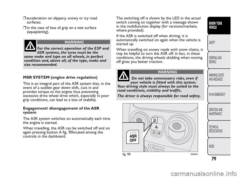
again pressing button A fig. 90located among the
controls in the dashboard.The switching off is shown by the LED in the actual
switch coming on together with a message shown
in the multifunction display (for versions/markets,
where provided).
If the ASR is switched off when driving, it is
automatically switched on again when the vehicle is
started up.
When travelling on snowy roads with snow chains, it
may be helpful to turn the ASR off: in fact, in these
conditions, the driving wheels skidding when moving
off gives you better traction.
WARNING
Do not take unnecessary risks, even if
y
our vehicle is fitted with this system.
Your driving style must always be suited to the
road conditions, visibility and traffic .
The driver is always responsible for road safety.
fig. 90F0T0317
79
KNOW YOUR
VEHICLE
SAFETY
ST
ARTING AND
DRIVING
WARNING LIGHTS
AND MESSAGES
IN AN EMERGENCY
SERVICING AND
MAINTENANCE
TECHNICAL
SPECIFICATIONS
INDEX
Page 81 of 230
For the correct operation of the ASR system, the
tyres must absolutely be the same make and type on
all wheels, in perfect condition and, above all, of
the type, make and size specified.
FAILURE INDICATIONS
In the event of a failure, the ASR system will be
automatically switched off and warning light
will
appear permanently on the instrument panel along
with a message on the multifunction display (for
versions/markets where provided) (see “Warning
lights and messages”). In this case, contact a Fiat
Dealership as soon as possible.
TRACTION PLUS SYSTEM
(for versions/markets, where provided)
Traction Plus is a help with driving and setting off in
poor grip conditions (snow, ice, mud, etc.) which
allows the drive force to be evenly distributed over
the same axle when both wheels are slipping.
In effect, Traction Plus acts by braking the wheels
with poor grip (or those slipping more than the
others), thereby transferring the drive force to those
which have more grip on the ground.
This function can be turned on manually by pressing
the T+ button fig. 91 on the dashboard and works
below a level of 30 km/h. Over this speed, it is
automatically deactivated (the LED on the button is
still on) and it is reactivated again when the speed
is below 30 km/h.
80
KNOW YOUR
VEHICLE
SAFETY
ST
ARTING AND
DRIVING
WARNING LIGHTS
AND MESSAGES
IN AN EMERGENCY
SERVICING AND
MAINTENANCE
TECHNICAL
SPECIFICATIONS
INDEX
Page 82 of 230
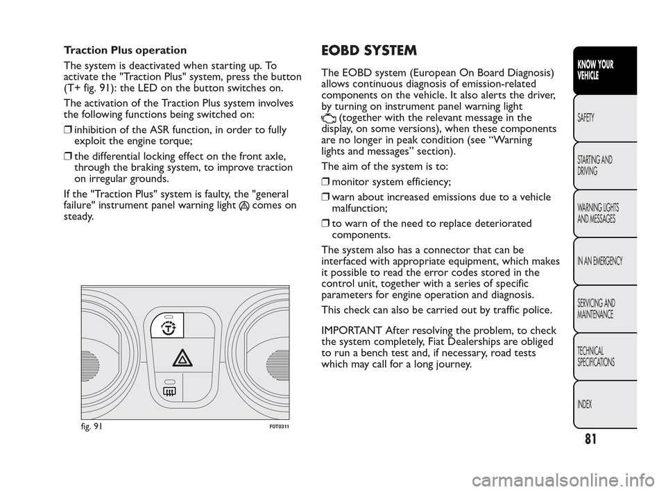
Traction Plus operation
The system is deactivated when starting up. To
activate the "Traction Plus" system, press the button
(T+ fig. 91): the LED on the button switches on.
The activation of the Traction Plus system involves
the following functions being switched on:
❒inhibition of the ASR function, in order to fully
exploit the engine torque;
❒the differential locking effect on the front axle,
through the braking system, to improve traction
on irregular grounds.
If the "Traction Plus" system is faulty, the "general
failure" instrument panel warning light
comes on
steady.
EOBD SYSTEM
The EOBD system (European On Board Diagnosis)
allows continuous diagnosis of emission-related
components on the vehicle. It also alerts the driver,
by turning on instrument panel warning light
(together with the relevant message in the
display, on some versions), when these components
are no longer in peak condition (see “Warning
lights and messages” section).
The aim of the system is to:
❒monitor system efficiency;
❒warn about increased emissions due to a vehicle
malfunction;
❒to warn of the need to replace deteriorated
components.
The system also has a connector that can be
interfaced with appropriate equipment, which makes
it possible to read the error codes stored in the
control unit, together with a series of specific
parameters for engine operation and diagnosis.
This check can also be carried out by traffic police.
IMPORTANT After resolving the problem, to check
the system completely, Fiat Dealerships are obliged
to run a bench test and, if necessary, road tests
which may call for a long journey.
fig. 91F0T0311
81
KNOW YOUR
VEHICLE
SAFETY
ST
ARTING AND
DRIVING
WARNING LIGHTS
AND MESSAGES
IN AN EMERGENCY
SERVICING AND
MAINTENANCE
TECHNICAL
SPECIFICATIONS
INDEX
Page 83 of 230
WARNING
Go to a Fiat Dealership as soon as
possible
if warning light
either does
not light up when the key is turned to MAR to if
while travelling the warning lights comes on
either steady or blinking (along with a message
on the display).The operation of warning light
may be checked by the traffic police using
specific devices. Follow the laws in force in
the country where you are driving.
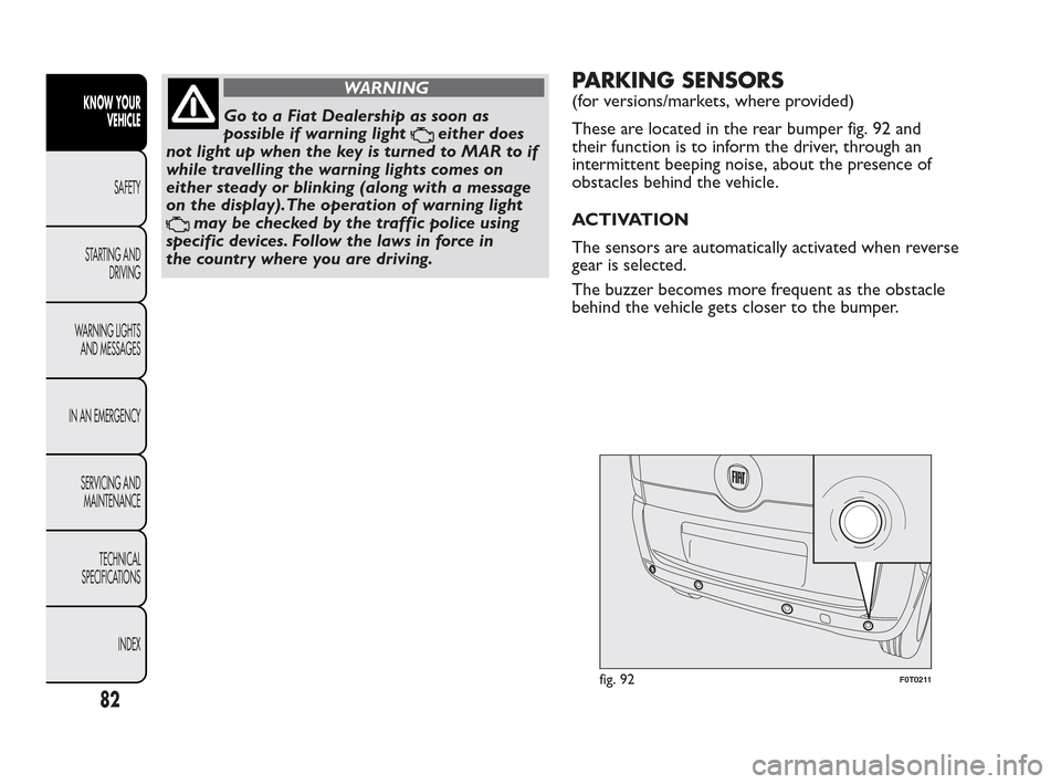
PARKING SENSORS
(for versions/markets, where provided)
These are located in the rear bumper fig. 92 and
their function is to inform the driver, through an
intermittent beeping noise, about the presence of
obstacles behind the vehicle.
ACTIVATION
The sensors are automatically activated when reverse
gear is selected.
The buzzer becomes more frequent as the obstacle
behind the vehicle gets closer to the bumper.
fig. 92F0T0211
82
KNOW YOUR
VEHICLE
SAFETY
ST
ARTING AND
DRIVING
WARNING LIGHTS
AND MESSAGES
IN AN EMERGENCY
SERVICING AND
MAINTENANCE
TECHNICAL
SPECIFICATIONS
INDEX
Page 90 of 230
FUEL CUT-OFF SYSTEM
This system is triggered after a collision as follows by:
❒cutting off fuel supply and consequently stopping
the engine
❒automatically unlocking the doors
❒turning on the lights inside the vehicle.
When the system has been triggered, the message
“Fuel cut off, see handbook” is displayed on some
versions.
Check carefully for fuel leaks, for instance in the
engine compartment, under the vehicle or near the
tank area.
After a crash, turn the ignition key to STOP to avoid
draining the battery.The following procedure should be carried out to
restore the correct operation of the vehicle:
❒turn the ignition key to the ON position;
❒turn on the right direction indicator;
❒turn off the right direction indicator;
❒turn on the left direction indicator;
❒turn off the left direction indicator;
❒turn on the right direction indicator;
❒turn off the right direction indicator;
❒turn on the left direction indicator;
❒turn off the left direction indicator;
❒turn the ignition key to the OFF position.
WARNING
If, after a crash, you smell fuel or notice
leaks
from the fuel system, do not rearm
the system to avoid the risk of fire.
89
KNOW YOUR
VEHICLE
SAFETY
ST
ARTING AND
DRIVING
WARNING LIGHTS
AND MESSAGES
IN AN EMERGENCY
SERVICING AND
MAINTENANCE
TECHNICAL
SPECIFICATIONS
INDEX
Page 91 of 230
PROTECTING THE ENVIRONMENT
The following devices are used for reducing diesel
fuel engine emissions:
❒oxidising catalytic converter
❒exhaust gas recirculation system (EGR)
❒diesel particulate filter (DPF) (for versions/
markets, where provided).DIESEL PARTICULATE FILTER (DPF)
(for versions/markets, where provided)
The Diesel Particulate Filter is a mechanical filter,
integral to the exhaust system, that physically traps
carbon particulates present in the exhaust gases
of diesel engines.
It is needed to eliminate almost all particulates in
compliance with current/future legislation. During
normal use of the vehicle, the engine control unit
records a set of data (e.g.: travel time, type of route,
temperatures, etc.) and it will then calculate how
much particulate has been trapped by the filter.
Since this filter physically traps particulate, it should
be regenerated (cleaned) at regular intervals by
burning the carbon particles. The regeneration
procedure is controlled automatically by the engine
management control unit according to the filter
conditions and vehicle use conditions.
During regeneration, the following may occur: a
limited increase in the engine speed, activation of the
fan, a limited increase in fumes and high
temperatures at the exhaust.
These are not faults; they do not impair vehicle
performance or damage the environment. If
the dedicated message is displayed, refer to the
“Warning lights and messages” section.
90
KNOW YOUR
VEHICLE
SAFETY
ST
ARTING AND
DRIVING
WARNING LIGHTS
AND MESSAGES
IN AN EMERGENCY
SERVICING AND
MAINTENANCE
TECHNICAL
SPECIFICATIONS
INDEX
Page 103 of 230
ISOFIX CHILD SEAT ASSEMBLY
SETUP
(for versions/markets, where provided)
Provisions are made on some versions of the vehicle
to fit Universal Isofix child seats. Isofix is a new
European standardised system for carrying children
safely.Isofix systems can be fitted alongside traditional child
seats.
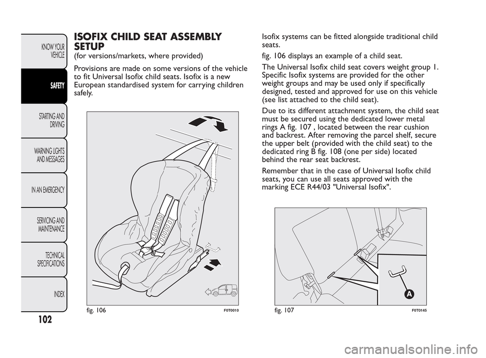
fig. 106 displays an example of a child seat.
The Universal Isofix child seat covers weight group 1.
Specific Isofix systems are provided for the other
weight groups and may be used only if specifically
designed, tested and approved for use on this vehicle
(see list attached to the child seat).
Due to its different attachment system, the child seat
must be secured using the dedicated lower metal
rings A fig. 107 , located between the rear cushion
and backrest. After removing the parcel shelf, secure
the upper belt (provided with the child seat) to the
dedicated ring B fig. 108 (one per side) located
behind the rear seat backrest.
Remember that in the case of Universal Isofix child
seats, you can use all seats approved with the
marking ECE R44/03 "Universal Isofix".
fig. 106F0T0010fig. 107F0T0145
102
KNOW YOUR
VEHICLE
SAFETY
STARTING AND
DRIVING
W
ARNING LIGHTS
AND MESSAGES
IN AN EMERGENCY
SERVICING AND
MAINTENANCE
TECHNICAL
SPECIFICATIONS
INDEX