key FIAT QUBO 2015 1.G User Guide
[x] Cancel search | Manufacturer: FIAT, Model Year: 2015, Model line: QUBO, Model: FIAT QUBO 2015 1.GPages: 231, PDF Size: 5.01 MB
Page 27 of 231
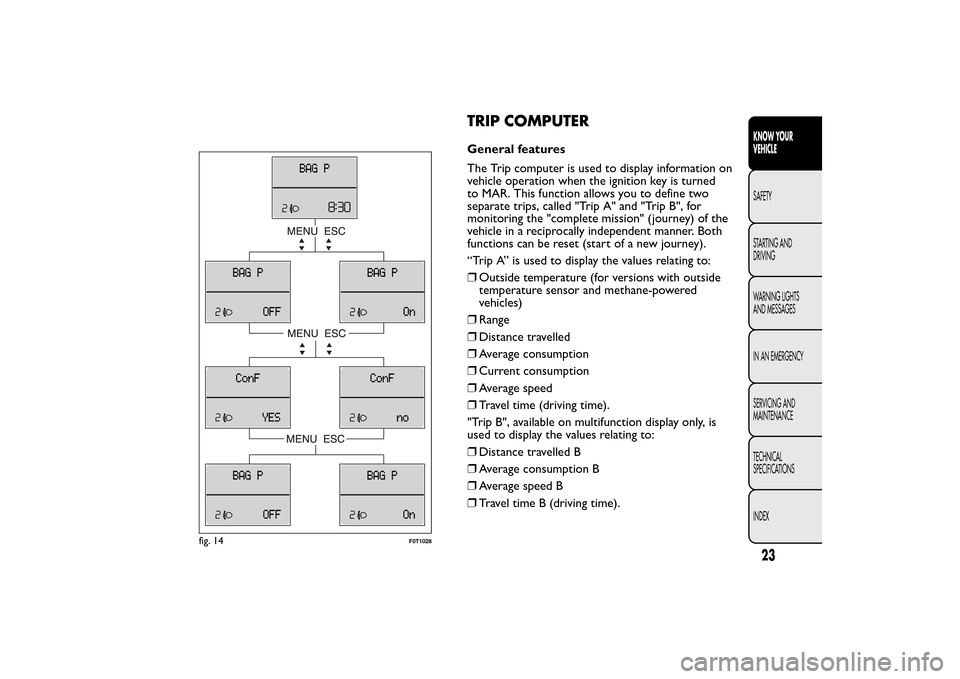
TRIP COMPUTERGeneral features
The Trip computer is used to display information on
vehicle operation when the ignition key is turned
to MAR. This function allows you to define two
separate trips, called "Trip A" and "Trip B", for
monitoring the "complete mission" (journey) of the
vehicle in a reciprocally independent manner. Both
functions can be reset (start of a new journey).
“Trip A” is used to display the values relating to:
❒Outside temperature (for versions with outside
temperature sensor and methane-powered
vehicles)
❒Range
❒Distance travelled
❒Average consumption
❒Current consumption
❒Average speed
❒Travel time (driving time).
"Trip B", available on multifunction display only, is
used to display the values relating to:
❒Distance travelled B
❒Average consumption B
❒Average speed B
❒Travel time B (driving time).
fig. 14
F0T1028
23KNOW YOUR
VEHICLESAFETY
STARTING AND
DRIVING
WARNING LIGHTS
AND MESSAGES
IN AN EMERGENCY
SERVICING AND
MAINTENANCE
TECHNICAL
SPECIFICATIONS
INDEX
Page 29 of 231
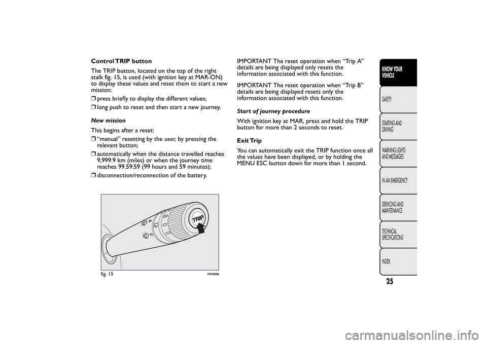
Control TRIP button
The TRIP button, located on the top of the right
stalk fig. 15, is used (with ignition key at MAR-ON)
to display these values and reset them to start a new
mission:
❒press briefly to display the different values;
❒long push to reset and then start a new journey.
New mission
This begins after a reset:
❒“manual” resetting by the user, by pressing the
relevant button;
❒automatically when the distance travelled reaches
9,999.9 km (miles) or when the journey time
reaches 99.59:59 (99 hours and 59 minutes);
❒disconnection/reconnection of the battery.IMPORTANT The reset operation when “Trip A”
details are being displayed only resets the
information associated with this function.
IMPORTANT The reset operation when “Trip B”
details are being displayed resets only the
information associated with this function.
Start of journey procedure
With ignition key at MAR, press and hold the TRIP
button for more than 2 seconds to reset.
Exit Trip
You can automatically exit the TRIP function once all
the values have been displayed, or by holding the
MENU ESC button down for more than 1 second.
fig. 15
F0T0038
25KNOW YOUR
VEHICLESAFETY
STARTING AND
DRIVING
WARNING LIGHTS
AND MESSAGES
IN AN EMERGENCY
SERVICING AND
MAINTENANCE
TECHNICAL
SPECIFICATIONS
INDEX
Page 31 of 231
When the function is enabled, the LED on the
button turns on.FOLDAWAY PASSENGER SEAT
(for versions/markets, where provided)
The passenger seat can be folded away on some
versions.
IMPORTANT Move the seat only when there are no
rear passengers.
Folding the seat
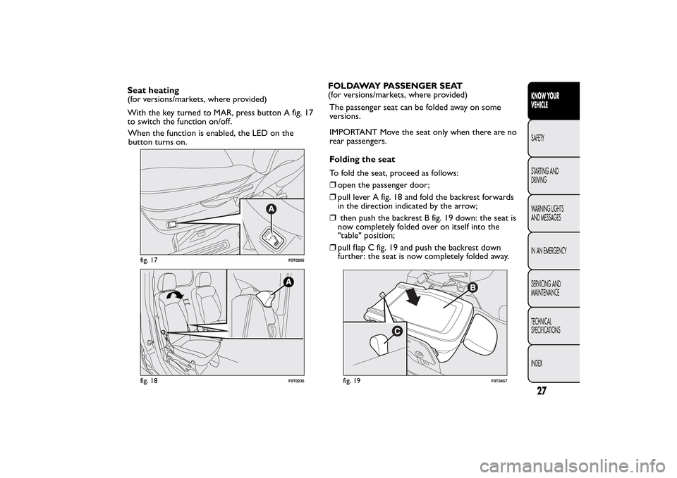
To fold the seat, proceed as follows:
❒open the passenger door;
❒pull lever A fig. 18 and fold the backrest forwards
in the direction indicated by the arrow;
❒then push the backrest B fig. 19 down: the seat is
now completely folded over on itself into the
"table" position;
❒pull flap C fig. 19 and push the backrest down
further: the seat is now completely folded away.
fig. 17
F0T0205
fig. 18
F0T0235
fig. 19
F0T0457
27KNOW YOUR
VEHICLESAFETY
STARTING AND
DRIVING
WARNING LIGHTS
AND MESSAGES
IN AN EMERGENCY
SERVICING AND
MAINTENANCE
TECHNICAL
SPECIFICATIONS
INDEX
Seat heating
(for versions/markets, where provided)
With the key turned to MAR, press button A fig. 17
to switch the function on/off.
Page 37 of 231
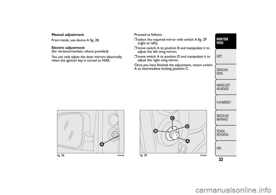
Manual adjustment
From inside, use device A fig. 28.
Electric adjustment
(for versions/markets, where provided)
You can only adjust the door mirrors electrically
when the ignition key is turned to MAR.Proceed as follows:
❒select the required mirror with switch A fig. 29
(right or left);
❒move switch A to position B and manipulate it to
adjust the left wing mirror;
❒move switch A to position D and manipulate it to
adjust the right wing mirror.
Once you have finished the adjustment, return switch
A to intermediate locking position C.
fig. 28
F0T0194
fig. 29
F0T0041
33KNOW YOUR
VEHICLESAFETY
STARTING AND
DRIVING
WARNING LIGHTS
AND MESSAGES
IN AN EMERGENCY
SERVICING AND
MAINTENANCE
TECHNICAL
SPECIFICATIONS
INDEX
Page 45 of 231
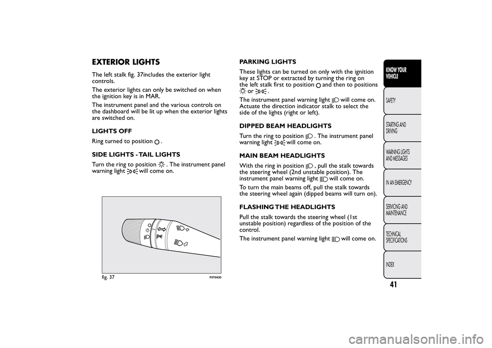
EXTERIOR LIGHTSThe left stalk fig. 37includes the exterior light
controls.
The exterior lights can only be switched on when
the ignition key is in MAR.
The instrument panel and the various controls on
the dashboard will be lit up when the exterior lights
are switched on.
LIGHTS OFF
Ring turned to position
.
SIDE LIGHTS - TAIL LIGHTS
Turn the ring to position. The instrument panel
warning light
will come on.PARKING LIGHTS
These lights can be turned on only with the ignition
key at STOP or extracted by turning the ring on
the left stalk first to position
and then to positions
or
.
The instrument panel warning light
will come on.
Actuate the direction indicator stalk to select the
side of the lights (right or left).
DIPPED BEAM HEADLIGHTS
Turn the ring to position
. The instrument panel
warning light
will come on.
MAIN BEAM HEADLIGHTS
With the ring in position
, pull the stalk towards
the steering wheel (2nd unstable position). The
instrument panel warning light
will come on.
To turn the main beams off, pull the stalk towards
the steering wheel again (dipped beams will turn on).
FLASHING THE HEADLIGHTS
Pull the stalk towards the steering wheel (1st
unstable position) regardless of the position of the
control.
The instrument panel warning light
will come on.
fig. 37
F0T0430
41KNOW YOUR
VEHICLESAFETY
STARTING AND
DRIVING
WARNING LIGHTS
AND MESSAGES
IN AN EMERGENCY
SERVICING AND
MAINTENANCE
TECHNICAL
SPECIFICATIONS
INDEX
Page 46 of 231
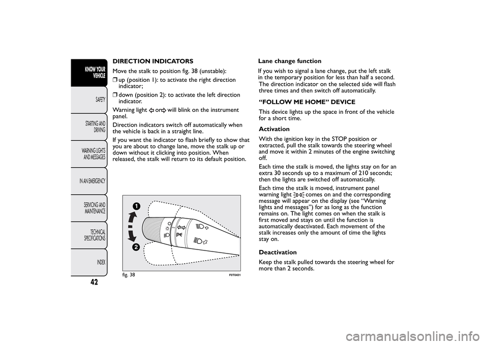
DIRECTION INDICATORS
Move the stalk to position fig. 38 (unstable):
❒up (position 1): to activate the right direction
indicator;
❒down (position 2): to activate the left direction
indicator.
Warning light
or
will blink on the instrument
panel.
Direction indicators switch off automatically when
the vehicle is back in a straight line.
If you want the indicator to flash briefly to show that
you are about to change lane, move the stalk up or
down without it clicking into position. When
released, the stalk will return to its default position.Lane change function
If you wish to signal a lane change, put the left stalk
in the temporary position for less than half a second.
The direction indicator on the selected side will flash
three times and then switch off automatically.
“FOLLOW ME HOME” DEVICE
This device lights up the space in front of the vehicle
for a short time.
Activation
With the ignition key in the STOP position or
extracted, pull the stalk towards the steering wheel
and move it within 2 minutes of the engine switching
off.
Each time the stalk is moved, the lights stay on for an
extra 30 seconds up to a maximum of 210 seconds;
then the lights are switched off automatically.
Each time the stalk is moved, instrument panel
warning light
comes on and the corresponding
message will appear on the display (see “Warning
lights and messages”) for as long as the function
remains on. The light comes on when the stalk is
first moved and stays on until the function is
automatically deactivated. Each movement of the
stalk increases only the amount of time the lights
stay on.
Deactivation
Keep the stalk pulled towards the steering wheel for
more than 2 seconds.
fig. 38
F0T0431
42KNOW YOUR
VEHICLE
SAFETY
STARTING AND
DRIVING
WARNING LIGHTS
AND MESSAGES
IN AN EMERGENCY
SERVICING AND
MAINTENANCE
TECHNICAL
SPECIFICATIONS
INDEX
Page 50 of 231
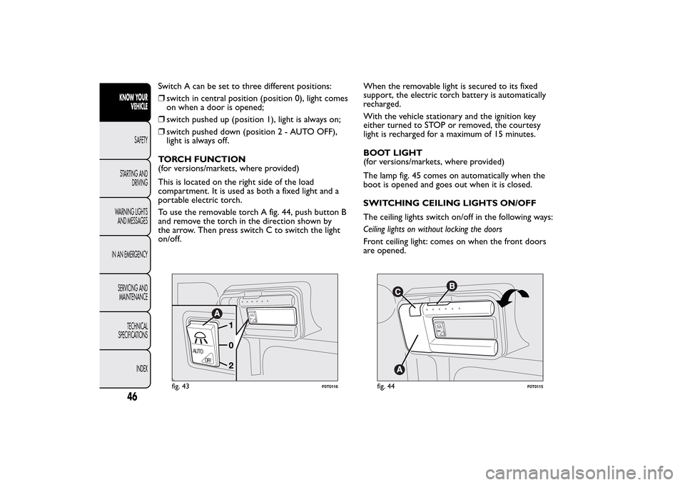
Switch A can be set to three different positions:
❒switch in central position (position 0), light comes
on when a door is opened;
❒switch pushed up (position 1), light is always on;
❒switch pushed down (position2-AUTOOFF),
light is always off.
TORCH FUNCTION
(for versions/markets, where provided)
This is located on the right side of the load
compartment. It is used as both a fixed light and a
portable electric torch.
To use the removable torch A fig. 44, push button B
and remove the torch in the direction shown by
the arrow. Then press switch C to switch the light
on/off.When the removable light is secured to its fixed
support, the electric torch battery is automatically
recharged.
With the vehicle stationary and the ignition key
either turned to STOP or removed, the courtesy
light is recharged for a maximum of 15 minutes.
BOOT LIGHT
(for versions/markets, where provided)
The lamp fig. 45 comes on automatically when the
boot is opened and goes out when it is closed.
SWITCHING CEILING LIGHTS ON/OFF
The ceiling lights switch on/off in the following ways:
Ceiling lights on without locking the doors
Front ceiling light: comes on when the front doors
are opened.
AUTO
AUTO
OFF
fig. 43
F0T0116
A
UT
O
fig. 44
F0T0115
46KNOW YOUR
VEHICLE
SAFETY
STARTING AND
DRIVING
WARNING LIGHTS
AND MESSAGES
IN AN EMERGENCY
SERVICING AND
MAINTENANCE
TECHNICAL
SPECIFICATIONS
INDEX
Page 51 of 231
Rear ceiling light: on manually.
Removable ceiling light (alternative to rear ceiling
light): on manually (fixed part).
Ceiling lights off when locking the doors
Front and rear ceiling light (also with optional
removable ceiling light): off (faded out) when the
sliding side doors, rear swing doors or front doors
are closed.
With independent load compartment
Front ceiling light: fades out when the front doors
are closed.
Rear ceiling light (also with optional removable
ceiling light): off (faded out) closing the rear doors.
COMMANDSHAZARD LIGHTS
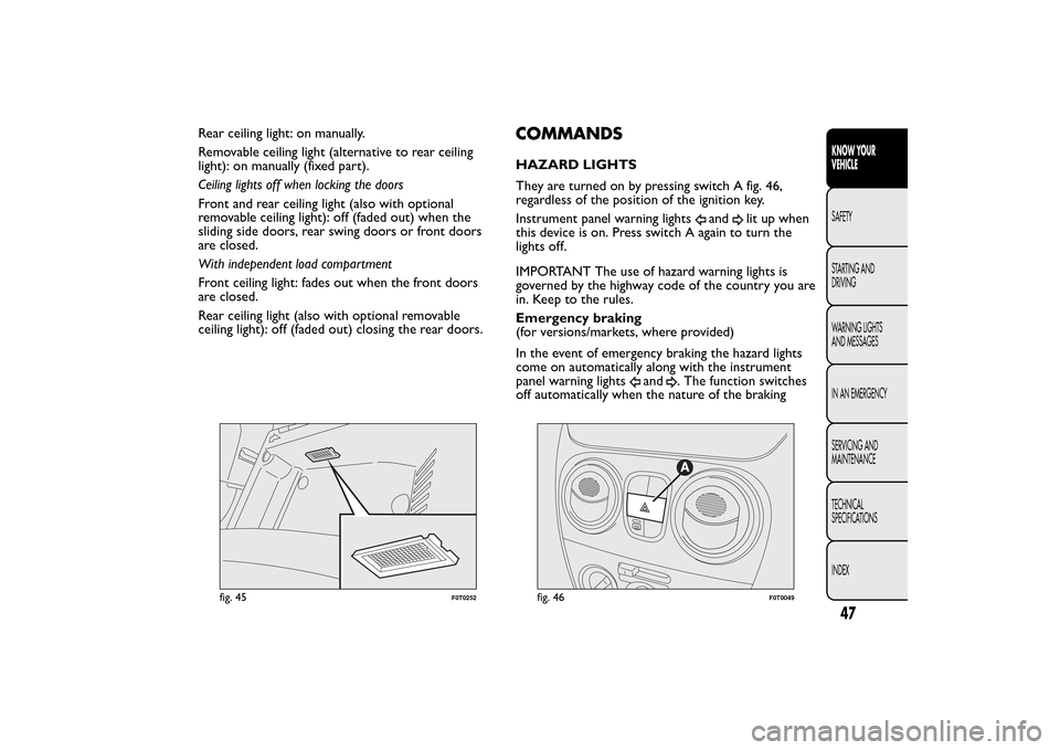
They are turned on by pressing switch A fig. 46,
regardless of the position of the ignition key.
Instrument panel warning lights
and
lit up when
this device is on. Press switch A again to turn the
lights off.
IMPORTANT The use of hazard warning lights is
governed by the highway code of the country you are
in. Keep to the rules.
Emergency braking
(for versions/markets, where provided)
In the event of emergency braking the hazard lights
come on automatically along with the instrument
panel warning lights
and
. The function switches
off automatically when the nature of the braking
fig. 45
F0T0252
fig. 46
F0T0049
47KNOW YOUR
VEHICLESAFETY
STARTING AND
DRIVING
WARNING LIGHTS
AND MESSAGES
IN AN EMERGENCY
SERVICING AND
MAINTENANCE
TECHNICAL
SPECIFICATIONS
INDEX
Page 53 of 231
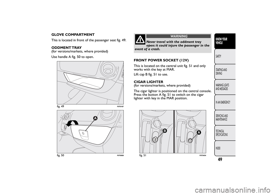
GLOVE COMPARTMENT
This is located in front of the passenger seat fig. 49.
ODDMENT TRAY
(for versions/markets, where provided)
Use handle A fig. 50 to open.
WARNING
Never travel with the oddment tray
open: it could injure the passenger in the
event of a crash.
FRONT POWER SOCKET (12V)
This is located on the central unit fig. 51 and only
works with the key at MAR.
Lift cap B fig. 51 to use.
CIGAR LIGHTER
(for versions/markets, where provided)
The cigar lighter is positioned on the central console.
Press the button A fig. 51 to switch on the cigar
lighter with key in the MAR position.
fig. 49
F0T0187
fig. 50
F0T0069
fig. 51
F0T0454
49KNOW YOUR
VEHICLESAFETY
STARTING AND
DRIVING
WARNING LIGHTS
AND MESSAGES
IN AN EMERGENCY
SERVICING AND
MAINTENANCE
TECHNICAL
SPECIFICATIONS
INDEX
Page 56 of 231
DOORSDOOR CENTRAL LOCKING/UNLOCKING
Locking from the outside
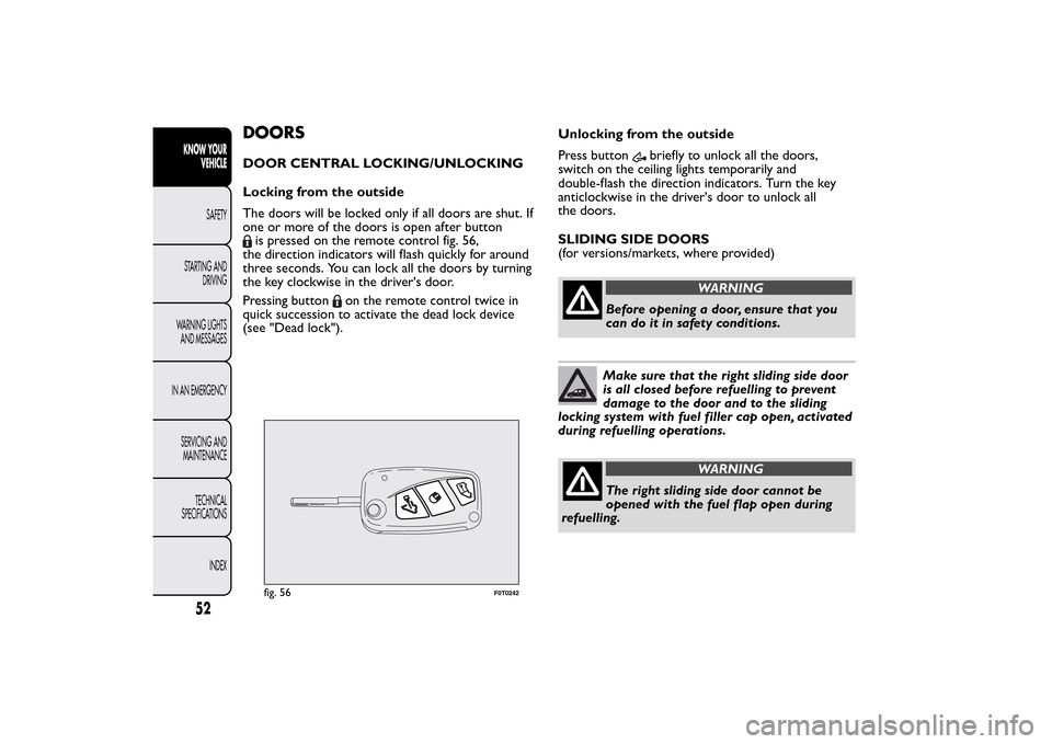
The doors will be locked only if all doors are shut. If
one or more of the doors is open after buttonis pressed on the remote control fig. 56,
the direction indicators will flash quickly for around
three seconds. You can lock all the doors by turning
the key clockwise in the driver's door.
Pressing button
on the remote control twice in
quick succession to activate the dead lock device
(see "Dead lock").Unlocking from the outside
Press button
briefly to unlock all the doors,
switch on the ceiling lights temporarily and
double-flash the direction indicators. Turn the key
anticlockwise in the driver's door to unlock all
the doors.
SLIDING SIDE DOORS
(for versions/markets, where provided)
WARNING
Before opening a door, ensure that you
can do it in safety conditions.Make sure that the right sliding side door
is all closed before refuelling to prevent
damage to the door and to the sliding
locking system with fuel filler cap open, activated
during refuelling operations.
WARNING
The right sliding side door cannot be
opened with the fuel flap open during
refuelling.
fig. 56
F0T0242
52KNOW YOUR
VEHICLE
SAFETY
STARTING AND
DRIVING
WARNING LIGHTS
AND MESSAGES
IN AN EMERGENCY
SERVICING AND
MAINTENANCE
TECHNICAL
SPECIFICATIONS
INDEX