clock FIAT QUBO 2015 1.G Owners Manual
[x] Cancel search | Manufacturer: FIAT, Model Year: 2015, Model line: QUBO, Model: FIAT QUBO 2015 1.GPages: 231, PDF Size: 5.01 MB
Page 21 of 231
Setup menu function
The menu fig. 13 comprises a series of functions in
"circular" arrangement, which can be selected by
pressing the
and
buttons to access the
different operations and settings described in the
following paragraphs. A submenu is provided for
some items (clock and unit setting).
The setup menu can be activated by pressing the
MENU ESC button briefly.
Press buttons
or
to scroll the setup menu
options.
Management modes differ according to the option
selected.
Selecting an option from the main menu without a
submenu:
- briefly press MENU ESC to select the main menu
option you wish to set;
- press
or
(with single presses) to select the
new setting;
- a short press on button MENU ESC will store the
setting and then return to the same main menu
option that was first selected.
Selecting an option from the main menu with a
submenu:
- briefly press the MENU ESC button to display the
first submenu option;
- press
or
(with single presses) to scroll all
the submenu options;- briefly press the MENU ESC button to select the
displayed submenu option and to open the relevant
setup menu;
- press
or
(with single presses) to select the
new setting for this submenu option;
- briefly press the MENU ESC button to store the
new setting and go back to the previous menu
option.
Selecting “Date” and “Set time”:
- briefly press MENU ESC to select the first value to
change (e.g. hours/minutes or year/month/day);
- press
or
(with single presses) to select the
new setting;
- briefly press MENU ESC to store the new setting
and go to the next setup menu option: if this is
the last one you will go back to the previous menu
option.
Hold down MENU ESC:
- to quit the set up menu if you are in the main
menu;
- to quit the main menu if you are in another point of
the menu (e.g. at submenu option setting level, at
submenu level or at main menu option setting level);
- to save only the settings already stored (and
confirmed by pressing the MENU ESC button).
The setup menu page is timed. Only the changes
already stored by pressing the MENU ESC button are
saved when you come out of the menu.
17KNOW YOUR
VEHICLESAFETY
STARTING AND
DRIVING
WARNING LIGHTS
AND MESSAGES
IN AN EMERGENCY
SERVICING AND
MAINTENANCE
TECHNICAL
SPECIFICATIONS
INDEX
Page 23 of 231
For activation/deactivation, proceed as follows:
- briefly press MENU ESC: On or Off will flash on
the display (depending on previous setting);
- press
or
to make your choice;
- press the MENU ESC button briefly to return to
the menu screen or give the button a long press
to return to the standard screen without storing.
Setting the clock (Set time)
This function allows you to set the clock through
two submenus: “Time” and “Mode”.
To carry out the adjustment, proceed as follows:
- briefly press the MENU ESC button and two
submenus (Time and Format) are displayed;
– press
or
to switch between the two
sub-menus;
- once you have selected a submenu, press MENU
ESC briefly;
- if selecting “Time”, briefly press MENU ESC - the
“hours” will flash on the display;
- press the
or
button to make the
adjustment;
- briefly press the MENU ESC button, which makes
the display flash the minutes;
- press the
or
button to make the
adjustment;
- when you select “Mode”, pressing MENU ESC
makes the mode flash on the display;- press the
or
button to carry out the
selection in 24h or 12h mode.
When you have made the required adjustments,
press SET ESC to go back to the submenu screen or
hold the button down to go back to the main menu
screen without saving.
- hold down MENU ESC again to go back to the
standard screen or main menu, depending on which
point in the menu you have reached.
Set date (Set Date)
This function allows updating of the date (day -
month - year).
To update, proceed as follows:
- briefly press MENU ESC: the day (dd) will flash on
the display;
- press the
or
button to make the
adjustment;
- briefly press MENU ESC: the month (mm) will flash
on the display;
- press the
or
button to make the
adjustment;
- briefly press MENU ESC: the year (yyyy) will flash
on the display;
- press the
or
button to make the
adjustment.
19KNOW YOUR
VEHICLESAFETY
STARTING AND
DRIVING
WARNING LIGHTS
AND MESSAGES
IN AN EMERGENCY
SERVICING AND
MAINTENANCE
TECHNICAL
SPECIFICATIONS
INDEX
Page 56 of 231
DOORSDOOR CENTRAL LOCKING/UNLOCKING
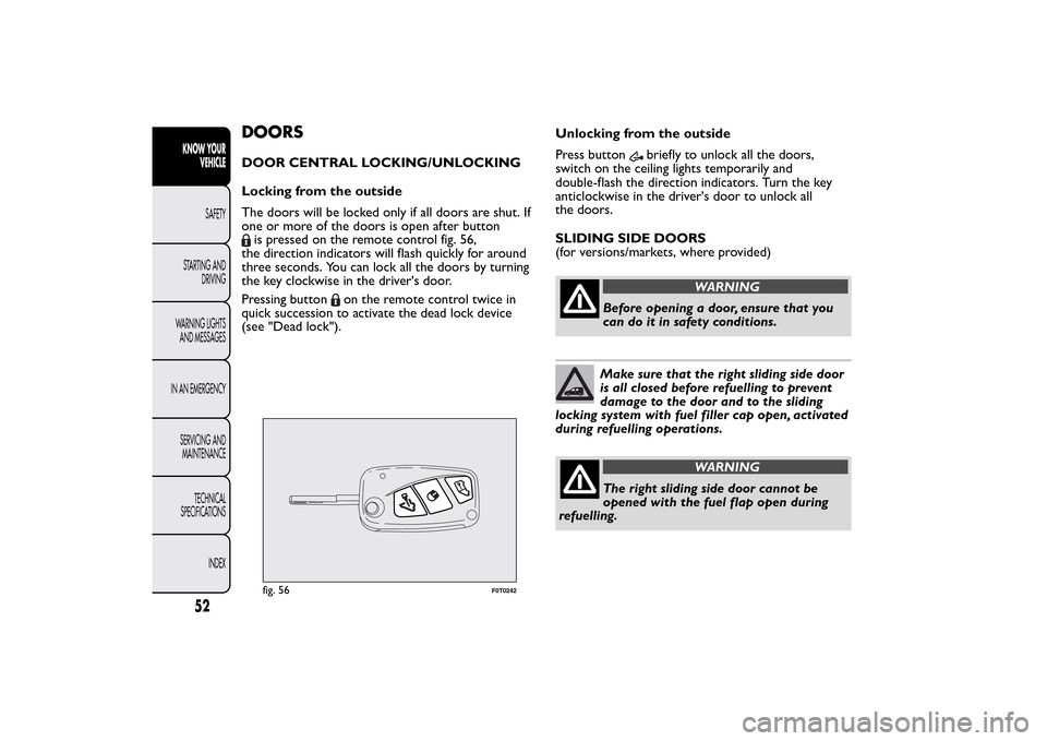
Locking from the outside
The doors will be locked only if all doors are shut. If
one or more of the doors is open after buttonis pressed on the remote control fig. 56,
the direction indicators will flash quickly for around
three seconds. You can lock all the doors by turning
the key clockwise in the driver's door.
Pressing button
on the remote control twice in
quick succession to activate the dead lock device
(see "Dead lock").Unlocking from the outside
Press button
briefly to unlock all the doors,
switch on the ceiling lights temporarily and
double-flash the direction indicators. Turn the key
anticlockwise in the driver's door to unlock all
the doors.
SLIDING SIDE DOORS
(for versions/markets, where provided)
WARNING
Before opening a door, ensure that you
can do it in safety conditions.Make sure that the right sliding side door
is all closed before refuelling to prevent
damage to the door and to the sliding
locking system with fuel filler cap open, activated
during refuelling operations.
WARNING
The right sliding side door cannot be
opened with the fuel flap open during
refuelling.
fig. 56
F0T0242
52KNOW YOUR
VEHICLE
SAFETY
STARTING AND
DRIVING
WARNING LIGHTS
AND MESSAGES
IN AN EMERGENCY
SERVICING AND
MAINTENANCE
TECHNICAL
SPECIFICATIONS
INDEX
Page 86 of 231
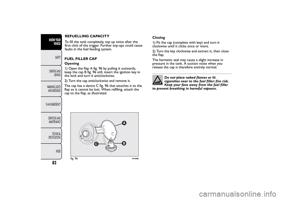
fig. 96
F0T0068
82KNOW YOUR
VEHICLE
SAFETY
STARTING AND
DRIVING
WARNING LIGHTS
AND MESSAGES
IN AN EMERGENCY
SERVICING AND
MAINTENANCE
TECHNICAL
SPECIFICATIONS
INDEX
REFUELLING CAPACITY
To fill the tank completely, top up twice after the
first click of the trigger. Further top-ups could cause
faults in the fuel feeding system.
FUEL FILLER CAP
Opening
1) Open the flap A fig. 96 by pulling it outwards,
keep the cap B fig. 96 still, insert the ignition key in
the lock and turn it anticlockwise.
2) Turn the cap anticlockwise and remove it.
The cap has a device C fig. 96 that attaches it to the
flap so it cannot be lost. When refilling, attach the
cap to the flap, as illustrated.Closing
1) Fit the cap (complete with key) and turn it
clockwise until it clicks once or more.
2) Turn the key clockwise and extract it, then close
the flap.
The hermetic seal may cause a slight increase in
pressure in the tank. A suction noise when you
release the cap is therefore entirely normal.
Do not place naked flames or lit
cigarettes near to the fuel filler: fire risk.
Keep your face away from the fuel filler
to prevent breathing in harmful vapours.
Page 109 of 231
Every control, repair and replacement operation
concerning the airbags must be carried out only at
Fiat Dealerships.
If you are having the vehicle scrapped, have the airbag
system deactivated at a Fiat Dealership first. If the
vehicle changes ownership, the new owner must be
informed of the method of use of air bags and the
above warnings and also be given this "Owner's
Handbook".
Pretensioners, front airbags and front side bags are
deployed differently according to the type of
collision. Non-deployment of one of these devices
does not therefore indicate a system fault.
WARNING
There may be a fault in the retaining
systems if the warning light
does not
light up when the key is turn on or remains on
while travelling (on some versions with a
message on the display). In this case, the airbags
or the pretensioners may not be activated in
the case of an accident or (more seldom) they
may be activated incorrectly. Contact a Fiat
Dealership immediately to have the system
checked.
WARNING
The expiration dates of the explosive
charge and the clock wire are shown on
a label contained in the glove box. Go to a Fiat
Dealership to have the devices replaced when
the expiration date approaches.
WARNING
Do not travel carrying objects in your
lap, in front of your chest or between
your lips (pipe, pencils, etc .): they could cause
severe injur y if the airbag is deployed.
105KNOW YOUR
VEHICLESAFETYSTARTING AND
DRIVING
WARNING LIGHTS
AND MESSAGES
IN AN EMERGENCY
SERVICING AND
MAINTENANCE
TECHNICAL
SPECIFICATIONS
INDEX
Page 146 of 231
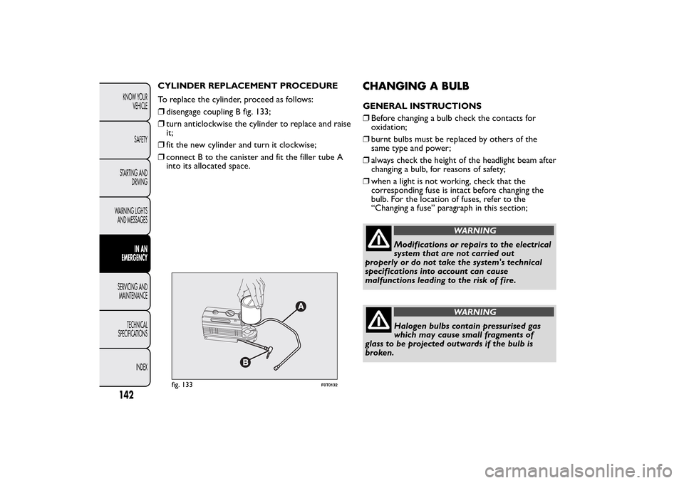
CYLINDER REPLACEMENT PROCEDURE
To replace the cylinder, proceed as follows:
❒disengage coupling B fig. 133;
❒turn anticlockwise the cylinder to replace and raise
it;
❒fit the new cylinder and turn it clockwise;
❒connect B to the canister and fit the filler tube A
into its allocated space.
CHANGING A BULBGENERAL INSTRUCTIONS
❒Before changing a bulb check the contacts for
oxidation;
❒burnt bulbs must be replaced by others of the
same type and power;
❒always check the height of the headlight beam after
changing a bulb, for reasons of safety;
❒when a light is not working, check that the
corresponding fuse is intact before changing the
bulb. For the location of fuses, refer to the
“Changing a fuse” paragraph in this section;
WARNING
Modifications or repairs to the electrical
system that are not carried out
properly or do not take the system's technical
specifications into account can cause
malfunctions leading to the risk of fire.
WARNING
Halogen bulbs contain pressurised gas
which may cause small fragments of
glass to be projected outwards if the bulb is
broken.
fig. 133
F0T0132
142KNOW YOUR
VEHICLE
SAFETY
STARTING AND
DRIVING
WARNING LIGHTS
AND MESSAGES
IN AN
EMERGENCY
SERVICING AND
MAINTENANCE
TECHNICAL
SPECIFICATIONS
INDEX
Page 148 of 231
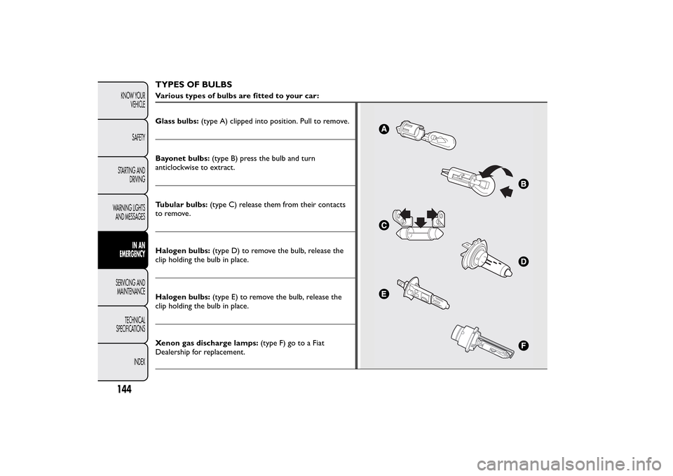
TYPES OF BULBSVarious types of bulbs are fitted to your car:
Glass bulbs:(type A) clipped into position. Pull to remove.Bayonet bulbs:(type B) press the bulb and turn
anticlockwise to extract.
Tubular bulbs:(type C) release them from their contacts
to remove.
Halogen bulbs:(type D) to remove the bulb, release the
clip holding the bulb in place.
Halogen bulbs:(type E) to remove the bulb, release the
clip holding the bulb in place.
Xenon gas discharge lamps:(type F) go to a Fiat
Dealership for replacement.
144KNOW YOUR
VEHICLE
SAFETY
STARTING AND
DRIVING
WARNING LIGHTS
AND MESSAGES
IN AN
EMERGENCY
SERVICING AND
MAINTENANCE
TECHNICAL
SPECIFICATIONS
INDEX
Page 150 of 231
CHANGING AN EXTERIOR BULBFor the type of bulb and corresponding power rating,
see the paragraph "Changing a bulb".
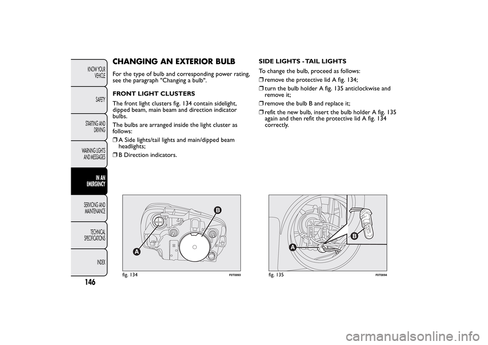
FRONT LIGHT CLUSTERS
The front light clusters fig. 134 contain sidelight,
dipped beam, main beam and direction indicator
bulbs.
The bulbs are arranged inside the light cluster as
follows:
❒A Side lights/tail lights and main/dipped beam
headlights;
❒B Direction indicators.SIDE LIGHTS - TAIL LIGHTS
To change the bulb, proceed as follows:
❒remove the protective lid A fig. 134;
❒turn the bulb holder A fig. 135 anticlockwise and
remove it;
❒remove the bulb B and replace it;
❒refit the new bulb, insert the bulb holder A fig. 135
again and then refit the protective lid A fig. 134
correctly.
fig. 134
F0T0093
fig. 135
F0T0094
146KNOW YOUR
VEHICLE
SAFETY
STARTING AND
DRIVING
WARNING LIGHTS
AND MESSAGES
IN AN
EMERGENCY
SERVICING AND
MAINTENANCE
TECHNICAL
SPECIFICATIONS
INDEX
Page 151 of 231
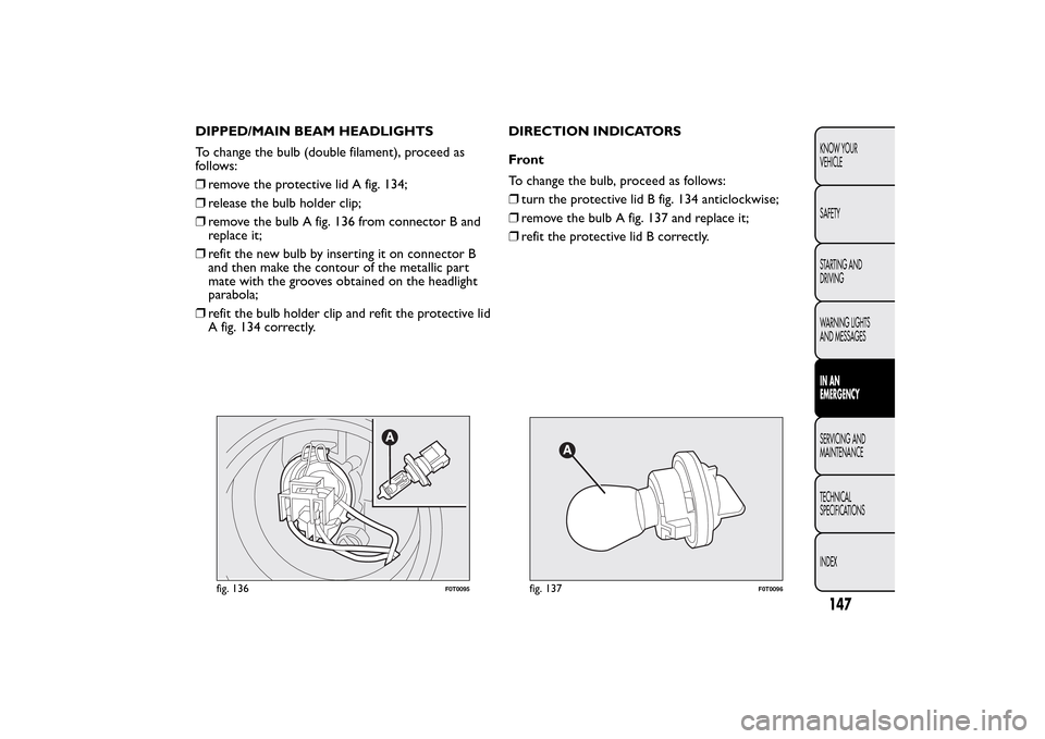
DIPPED/MAIN BEAM HEADLIGHTS
To change the bulb (double filament), proceed as
follows:
❒remove the protective lid A fig. 134;
❒release the bulb holder clip;
❒remove the bulb A fig. 136 from connector B and
replace it;
❒refit the new bulb by inserting it on connector B
and then make the contour of the metallic part
mate with the grooves obtained on the headlight
parabola;
❒refit the bulb holder clip and refit the protective lid
A fig. 134 correctly.DIRECTION INDICATORS
Front
To change the bulb, proceed as follows:
❒turn the protective lid B fig. 134 anticlockwise;
❒remove the bulb A fig. 137 and replace it;
❒refit the protective lid B correctly.
fig. 136
F0T0095
fig. 137
F0T0096
147KNOW YOUR
VEHICLE
SAFETY
STARTING AND
DRIVING
WARNING LIGHTS
AND MESSAGESIN AN
EMERGENCYSERVICING AND
MAINTENANCE
TECHNICAL
SPECIFICATIONS
INDEX
Page 152 of 231
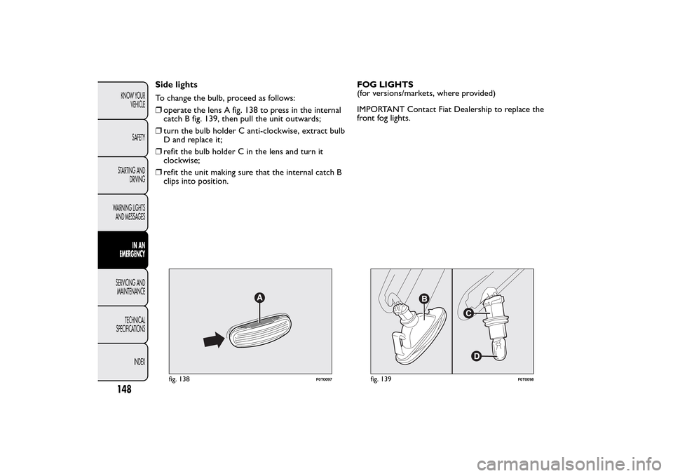
Side lights
To change the bulb, proceed as follows:
❒operate the lens A fig. 138 to press in the internal
catch B fig. 139, then pull the unit outwards;
❒turn the bulb holder C anti-clockwise, extract bulb
D and replace it;
❒refit the bulb holder C in the lens and turn it
clockwise;
❒refit the unit making sure that the internal catch B
clips into position.FOG LIGHTS
(for versions/markets, where provided)
IMPORTANT Contact Fiat Dealership to replace the
front fog lights.
fig. 138
F0T0097
fig. 139
F0T0098
148KNOW YOUR
VEHICLE
SAFETY
STARTING AND
DRIVING
WARNING LIGHTS
AND MESSAGES
IN AN
EMERGENCY
SERVICING AND
MAINTENANCE
TECHNICAL
SPECIFICATIONS
INDEX