FIAT QUBO 2016 1.G Manual Online
Manufacturer: FIAT, Model Year: 2016, Model line: QUBO, Model: FIAT QUBO 2016 1.GPages: 231, PDF Size: 5.02 MB
Page 81 of 231
PARKING SENSORS(for versions/markets, where provided)
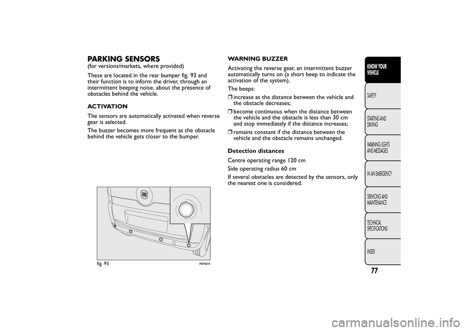
These are located in the rear bumper fig. 93 and
their function is to inform the driver, through an
intermittent beeping noise, about the presence of
obstacles behind the vehicle.
ACTIVATION
The sensors are automatically activated when reverse
gear is selected.
The buzzer becomes more frequent as the obstacle
behind the vehicle gets closer to the bumper.WARNING BUZZER
Activating the reverse gear, an intermittent buzzer
automatically turns on (a short beep to indicate the
activation of the system).
The beeps:
❒increase as the distance between the vehicle and
the obstacle decreases;
❒become continuous when the distance between
the vehicle and the obstacle is less than 30 cm
and stop immediately if the distance increases;
❒remains constant if the distance between the
vehicle and the obstacle remains unchanged.
Detection distances
Centre operating range 120 cm
Side operating radius 60 cm
If several obstacles are detected by the sensors, only
the nearest one is considered.
fig. 93
F0T0211
77KNOW YOUR
VEHICLESAFETY
STARTING AND
DRIVING
WARNING LIGHTS
AND MESSAGES
IN AN EMERGENCY
SERVICING AND
MAINTENANCE
TECHNICAL
SPECIFICATIONS
INDEX
Page 82 of 231
FAILURE INDICATIONS
Parking sensor failures are indicated, when engaging
reverse gear, by a three-second beep.
The sensor must be free of mud, dirt , snow
or ice in order for the system to work. Be
careful not to scratch or damage the
sensors while cleaning them. Avoid using dr y,
rough or hard cloths.The sensors should be
washed using clean water with the addition of car
shampoo if necessary.When using special
washing equipment such as high pressure jets or
steam cleaning, clean the sensors very quickly
keeping the jet more than 10 cm away.
OPERATION WITH TRAILER
The operation of the sensors is automatically
deactivated when the plug for the electric cable for
the trailer is inserted in the vehicle tow hook socket.
The sensors are automatically enabled again when
the trailer cable plug is removed.GENERAL WARNINGS
❒During parking manoeuvres, pay the utmost
attention to any obstacles that could be located
above or below the sensors.
❒Sometimes, objects located very near the rear of
the vehicle are not detected and could therefore
damage the vehicle or be damaged themselves.
❒The signals sent out by the sensors can be altered
by dirt, snow or ice deposited on the sensors or
by ultrasound systems (e.g. truck pneumatic brakes
or pneumatic drills) near the vehicle.
❒The parking sensors work properly with the swing
doors closed. If they are open, they can cause the
system to send false signals: always close the
rear doors.
WARNING
The ultimate responsibility when
parking and carrying out other
dangerous manoeuvres still rests with the
driver.When parking, make sure that no-one is
standing in the area, especially children or
animals. Parking sensors are designed to assist
drivers; however, you must always concentrate
fully during potentially dangerous manoeuvres,
even if carried out at low speeds.
78KNOW YOUR
VEHICLE
SAFETY
STARTING AND
DRIVING
WARNING LIGHTS
AND MESSAGES
IN AN EMERGENCY
SERVICING AND
MAINTENANCE
TECHNICAL
SPECIFICATIONS
INDEX
Page 83 of 231
RADIO(for versions/markets, where provided)
Read the Supplement attached to this Owner's
Handbook for the operation of the radio with
CD/MP3 player (for versions/markets, where
provided).
LIGHT SETUP
The system consists of:
❒radio power wires
❒speaker wires in front door panels
❒rear speaker wires (located next to parcel shelf )
(for versions/markets, where provided)
❒radio housing
❒antenna wires.
FULL SETUP
The system consists of:
❒radio power wires
❒speaker wires in front door panels
❒rear speaker wires (located next to parcel shelf )
(for versions/markets, where provided)
❒2 full-range Ø 130 mm placed in the door;
❒2 full-range speakers with Ø 100 mm placed on
the parcel shelf bracket (for versions / markets,
where provided);❒radio housing
❒antenna wires
❒antenna.
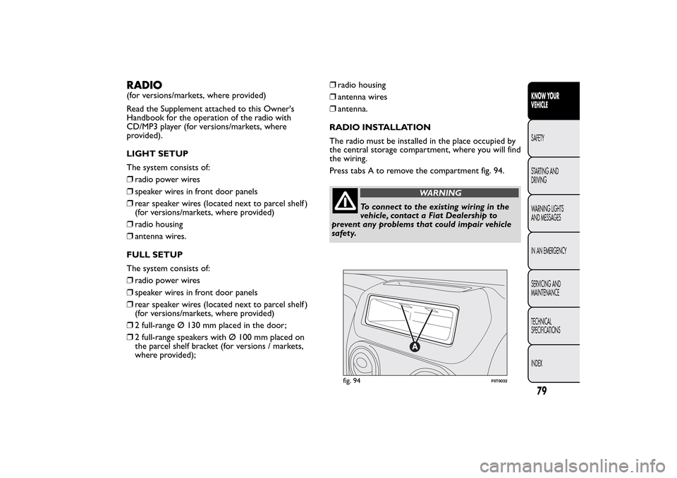
RADIO INSTALLATION
The radio must be installed in the place occupied by
the central storage compartment, where you will find
the wiring.
Press tabs A to remove the compartment fig. 94.
WARNING
To connect to the existing wiring in the
vehicle, contact a Fiat Dealership to
prevent any problems that could impair vehicle
safety.
fig. 94
F0T0032
79KNOW YOUR
VEHICLESAFETY
STARTING AND
DRIVING
WARNING LIGHTS
AND MESSAGES
IN AN EMERGENCY
SERVICING AND
MAINTENANCE
TECHNICAL
SPECIFICATIONS
INDEX
Page 84 of 231
INSTALLING ELECTRICAL/
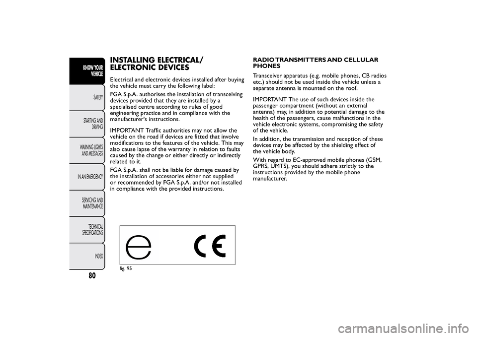
ELECTRONIC DEVICESElectrical and electronic devices installed after buying
the vehicle must carry the following label:
FGA S.p.A. authorises the installation of transceiving
devices provided that they are installed by a
specialised centre according to rules of good
engineering practice and in compliance with the
manufacturer's instructions.
IMPORTANT Traffic authorities may not allow the
vehicle on the road if devices are fitted that involve
modifications to the features of the vehicle. This may
also cause lapse of the warranty in relation to faults
caused by the change or either directly or indirectly
related to it.
FGA S.p.A. shall not be liable for damage caused by
the installation of accessories either not supplied
or recommended by FGA S.p.A. and/or not installed
in compliance with the provided instructions.RADIO TRANSMITTERS AND CELLULAR
PHONES
Transceiver apparatus (e.g. mobile phones, CB radios
etc.) should not be used inside the vehicle unless a
separate antenna is mounted on the roof.
IMPORTANT The use of such devices inside the
passenger compartment (without an external
antenna) may, in addition to potential damage to the
health of the passengers, cause malfunctions in the
vehicle electronic systems, compromising the safety
of the vehicle.
In addition, the transmission and reception of these
devices may be affected by the shielding effect of
the vehicle body.
With regard to EC-approved mobile phones (GSM,
GPRS, UMTS), you should adhere strictly to the
instructions provided by the mobile phone
manufacturer.
fig. 95
80KNOW YOUR
VEHICLE
SAFETY
STARTING AND
DRIVING
WARNING LIGHTS
AND MESSAGES
IN AN EMERGENCY
SERVICING AND
MAINTENANCE
TECHNICAL
SPECIFICATIONS
INDEX
Page 85 of 231
81KNOW YOUR
VEHICLESAFETY
STARTING AND
DRIVING
WARNING LIGHTS
AND MESSAGES
IN AN EMERGENCY
SERVICING AND
MAINTENANCE
TECHNICAL
SPECIFICATIONS
INDEX
REFUELLING THE VEHICLEDIESEL ENGINES
Operation at low temperatures
If the outside temperature is very low, the diesel
thickens due to the formation of paraffin clots with
consequent defective operation of the fuel supply
system.
In order to avoid these problems, different types of
diesel are distributed according to the season:
summer type, winter type and arctic type
(cold/mountain areas). If refuelling with diesel fuel
whose specifications are not suitable for the usage
temperature, it is advisable to mix TUTELA DIESEL
ART additive in the proportions shown on the
container with the fuel. Pour the additive into the
tank before the fuel.
When using or parking the vehicle for a long time in
the mountains or cold areas, it is advisable to refuel
using locally available diesel.
In this case, it is also advisable to keep the tank over
50% full.
For diesel engines, use only diesel fuel for
motor vehicles in accordance with EN590
European specifications.The use of other
products or mixtures may damage the engine
beyond repair and consequently invalidate the
warranty, due to the damage caused. If you
accidentally introduce other types of fuel into the
tank, do not start the engine. Empty the tank. If
the engine has been run for even an extremely
limited amount of time, you must not only drain
the fuel tank, but the rest of the supply circuit
as well.
Page 86 of 231
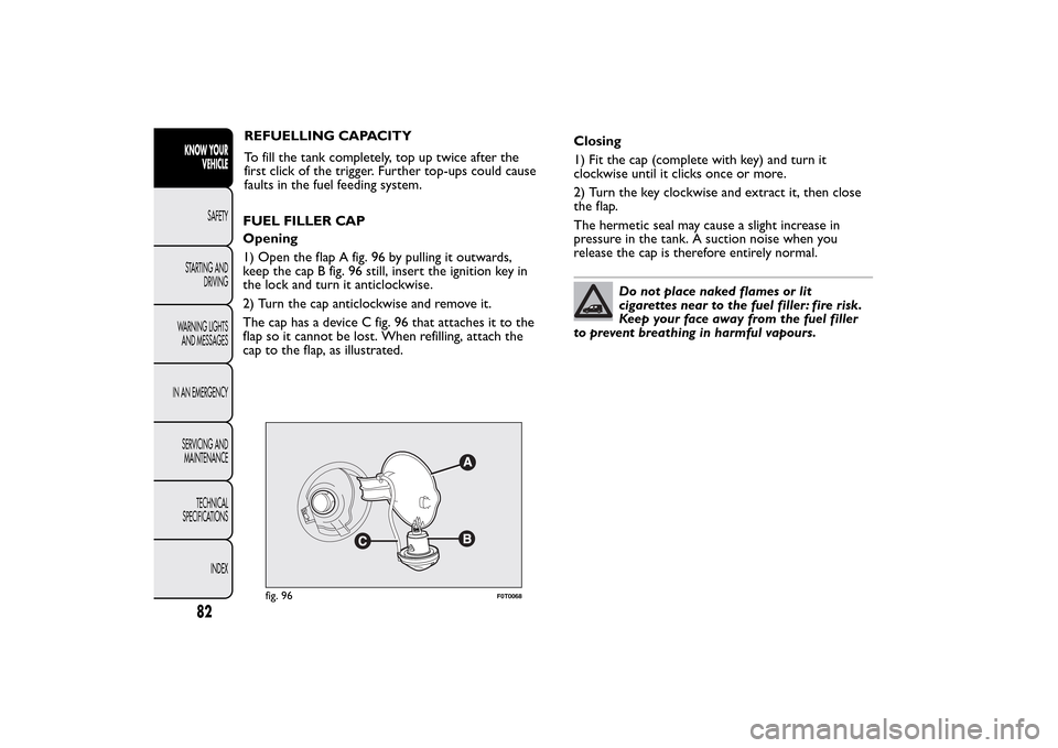
fig. 96
F0T0068
82KNOW YOUR
VEHICLE
SAFETY
STARTING AND
DRIVING
WARNING LIGHTS
AND MESSAGES
IN AN EMERGENCY
SERVICING AND
MAINTENANCE
TECHNICAL
SPECIFICATIONS
INDEX
REFUELLING CAPACITY
To fill the tank completely, top up twice after the
first click of the trigger. Further top-ups could cause
faults in the fuel feeding system.
FUEL FILLER CAP
Opening
1) Open the flap A fig. 96 by pulling it outwards,
keep the cap B fig. 96 still, insert the ignition key in
the lock and turn it anticlockwise.
2) Turn the cap anticlockwise and remove it.
The cap has a device C fig. 96 that attaches it to the
flap so it cannot be lost. When refilling, attach the
cap to the flap, as illustrated.Closing
1) Fit the cap (complete with key) and turn it
clockwise until it clicks once or more.
2) Turn the key clockwise and extract it, then close
the flap.
The hermetic seal may cause a slight increase in
pressure in the tank. A suction noise when you
release the cap is therefore entirely normal.
Do not place naked flames or lit
cigarettes near to the fuel filler: fire risk.
Keep your face away from the fuel filler
to prevent breathing in harmful vapours.
Page 87 of 231
FUEL CUT-OFF SYSTEMThis system is triggered after a collision as follows by:
❒the interruption of the fuel supply with the engine
consequently cutting out;
❒automatically unlocking the doors
❒turning on the lights inside the vehicle.
When the system has been triggered, the message
“Fuel cut off, see handbook” is displayed on some
versions.
Check carefully for fuel leaks, for instance in the
engine compartment, under the vehicle or near the
tank area.
After a crash, turn the ignition key to STOP to avoid
draining the battery.
The following procedure should be carried out to
restore the correct operation of the vehicle:
❒turn the ignition key to the ON position;
❒turn on the right direction indicator;
❒turn off the right direction indicator;
❒turn on the left direction indicator;
❒turn off the left direction indicator;
❒turn on the right direction indicator;
❒turn off the right direction indicator;
❒turn on the left direction indicator;
❒turn off the left direction indicator;
❒turn the ignition key to the OFF position.
WARNING
If, after an impact , you smell fuel or
notice leaks from the fuel system, do not
reactivate the system to avoid the risk of fire.
83KNOW YOUR
VEHICLESAFETY
STARTING AND
DRIVING
WARNING LIGHTS
AND MESSAGES
IN AN EMERGENCY
SERVICING AND
MAINTENANCE
TECHNICAL
SPECIFICATIONS
INDEX
Page 88 of 231
PROTECTING THE ENVIRONMENTThe following devices are used for reducing diesel
fuel engine emissions:
❒oxidising catalytic converter
❒exhaust gas recirculation system (EGR)
❒diesel particulate filter (DPF) (for versions/
markets, where provided).
DIESEL PARTICULATE FILTER (DPF)
(for versions/markets, where provided)
The Diesel Particulate Filter is a mechanical filter,
integral to the exhaust system, that physically traps
carbon particulates present in the exhaust gases
of diesel engines.
The diesel particulate filter has been adopted to
eliminate almost all particulates in compliance with
current/future regulations.
During normal use of the vehicle, the engine
management control unit records a set of data
(travel time, type of route, temperatures reached
etc.) and calculates how much particulate has been
trapped by the filter.Since this filter physically traps particulate, it must be
regenerated (cleaned) at regular intervals by burning
the carbon particles.
The regeneration procedure is managed
automatically by the engine management control unit
according to the filter conditions and vehicle use
conditions.
During regeneration, the following may occur: a
limited increase in the engine speed, activation of the
fan, a limited increase in fumes and high
temperatures at the exhaust.
These are not faults; they do not impair vehicle
performance or damage the environment. If
the dedicated message is displayed, refer to the
“Warning lights and messages” section.
84KNOW YOUR
VEHICLE
SAFETY
STARTING AND
DRIVING
WARNING LIGHTS
AND MESSAGES
IN AN EMERGENCY
SERVICING AND
MAINTENANCE
TECHNICAL
SPECIFICATIONS
INDEX
Page 89 of 231
SAFETY
SEAT BELTSUSING THE SEAT BELTS
Wear the belt keeping the torso upright and rested
against the backrest.
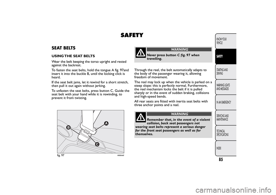
To fasten the seat belts, hold the tongue A fig. 97and
insert it into the buckle B, until the locking click is
heard.
If the seat belt jams, let it rewind for a short stretch,
then pull it out again without jerking.
To unfasten the seat belts, press button C. Guide the
seat belt with your hand while it is rewinding, to
prevent it from twisting.
WARNING
Never press button C fig. 97 when
travelling.
Through the reel, the belt automatically adapts to
the body of the passenger wearing it, allowing
freedom of movement.
The reel may lock up when the vehicle is parked on a
steep slope: this is perfectly normal. Furthermore,
the reel mechanism locks the belt if it is pulled
sharply or in the event of sudden braking, collisions
and high-speed bends.
All rear seats are fitted with inertia seat belts with
three anchor points and a reel.
WARNING
Remember that , in the event of a violent
collision, back seat passengers not
wearing seat belts represent a serious danger
for the front seat passengers as well as for
themselves.
fig. 97
F0T0147
85KNOW YOUR
VEHICLESAFETYSTARTING AND
DRIVING
WARNING LIGHTS
AND MESSAGES
IN AN EMERGENCY
SERVICING AND
MAINTENANCE
TECHNICAL
SPECIFICATIONS
INDEX
Page 90 of 231
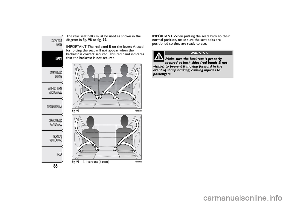
The rear seat belts must be used as shown in the
diagram in fig. 98 or fig. 99.
IMPORTANT The red band B on the levers A used
for folding the seat will not appear when the
backrest is correct secured. This red band indicates
that the backrest is not secured.IMPORTANT When putting the seats back to their
normal position, make sure the seat belts are
positioned so they are ready to use.
WARNING
Make sure the backrest is properly
secured at both sides (red bands B not
visible) to prevent it moving forward in the
event of sharp braking, causing injuries to
passengers.
fig. 98
F0T0193
fig. 99 - N1 versions (4 seats)
F0T0342
86KNOW YOUR
VEHICLE
SAFETY
STARTING AND
DRIVING
WARNING LIGHTS
AND MESSAGES
IN AN EMERGENCY
SERVICING AND
MAINTENANCE
TECHNICAL
SPECIFICATIONS
INDEX