FIAT QUBO 2017 1.G Owners Manual
Manufacturer: FIAT, Model Year: 2017, Model line: QUBO, Model: FIAT QUBO 2017 1.GPages: 260, PDF Size: 4.74 MB
Page 91 of 260
Engine restarting mode
WITH MANUAL GEARBOX
Press the clutch pedal to allow the engine to be
restarted.
WITH ROBOTISED GEARBOX
If the gear lever is in position N, place it in any other
gear, otherwise release the brake pedal or move
the gear lever to(+),(-)orR.
MANUAL ACTIVATION AND
DEACTIVATION
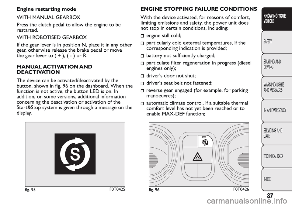
The device can be activated/deactivated by the
button, shown in fig. 96 on the dashboard. When the
function is not active, the button LED is on. In
addition, on some versions, additional information
concerning the deactivation or activation of the
Start&Stop system is given through a message on the
display.ENGINE STOPPING FAILURE CONDITIONS
With the device activated, for reasons of comfort,
limiting emissions and safety, the power unit does
not stop in certain conditions, including:
engine still cold;
particularly cold external temperatures, if the
corresponding indication is provided;
battery not sufficiently charged;
particulate filter regeneration in progress (diesel
engines only);
driver's door not shut;
driver's seat belt not fastened;
reverse gear engaged (for example, for parking
manoeuvres);
automatic climate control, if a suitable thermal
comfort level has not yet been reached or to
enable MAX-DEF function;
fig. 95F0T0425fig. 96F0T0426
87
KNOWING YOUR
VEHICLE
SAFETY
STARTING AND
DRIVING
WARNING LIGHTS
AND MESSAGES
IN AN EMERGENCY
SERVICING AND
CARE
TECHNICAL DATA
INDEX
Page 92 of 260
during the first period of use, to initialize the
system.
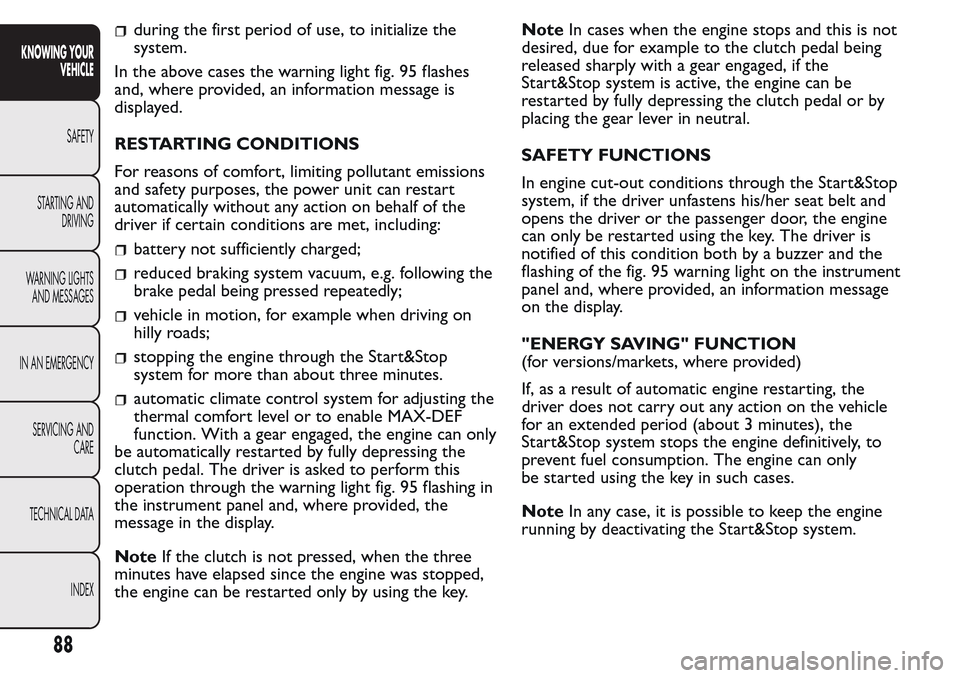
In the above cases the warning light fig. 95 flashes
and, where provided, an information message is
displayed.
RESTARTING CONDITIONS
For reasons of comfort, limiting pollutant emissions
and safety purposes, the power unit can restart
automatically without any action on behalf of the
driver if certain conditions are met, including:
battery not sufficiently charged;
reduced braking system vacuum, e.g. following the
brake pedal being pressed repeatedly;
vehicle in motion, for example when driving on
hilly roads;
stopping the engine through the Start&Stop
system for more than about three minutes.
automatic climate control system for adjusting the
thermal comfort level or to enable MAX-DEF
function. With a gear engaged, the engine can only
be automatically restarted by fully depressing the
clutch pedal. The driver is asked to perform this
operation through the warning light fig. 95 flashing in
the instrument panel and, where provided, the
message in the display.
NoteIf the clutch is not pressed, when the three
minutes have elapsed since the engine was stopped,
the engine can be restarted only by using the key.NoteIn cases when the engine stops and this is not
desired, due for example to the clutch pedal being
released sharply with a gear engaged, if the
Start&Stop system is active, the engine can be
restarted by fully depressing the clutch pedal or by
placing the gear lever in neutral.
SAFETY FUNCTIONS
In engine cut-out conditions through the Start&Stop
system, if the driver unfastens his/her seat belt and
opens the driver or the passenger door, the engine
can only be restarted using the key. The driver is
notified of this condition both by a buzzer and the
flashing of the fig. 95 warning light on the instrument
panel and, where provided, an information message
on the display.
"ENERGY SAVING" FUNCTION
(for versions/markets, where provided)
If, as a result of automatic engine restarting, the
driver does not carry out any action on the vehicle
for an extended period (about 3 minutes), the
Start&Stop system stops the engine definitively, to
prevent fuel consumption. The engine can only
be started using the key in such cases.
NoteIn any case, it is possible to keep the engine
running by deactivating the Start&Stop system.
88
KNOWING YOUR
VEHICLE
SAFETY
STARTING AND
DRIVING
WARNING LIGHTS
AND MESSAGES
IN AN EMERGENCY
SERVICING AND
CARE
TECHNICAL DATA
INDEX
Page 93 of 260
IRREGULAR OPERATION
In the event of malfunctions the Start&Stop system is
disabled. The driver is informed of the problem by
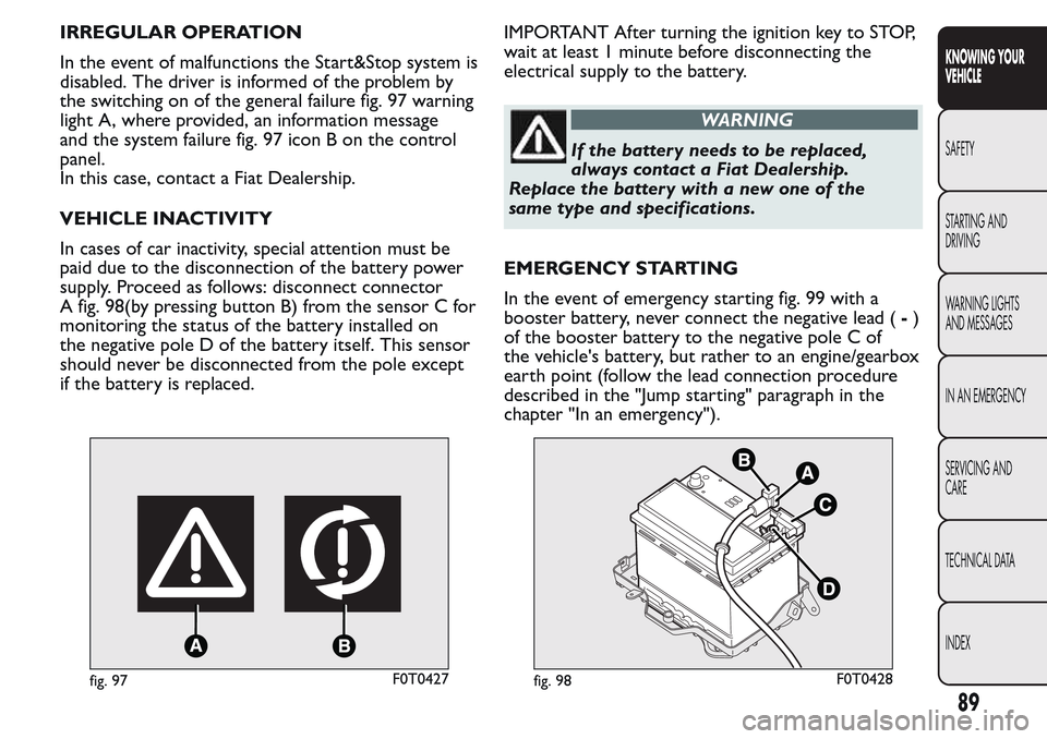
the switching on of the general failure fig. 97 warning
light A, where provided, an information message
and the system failure fig. 97 icon B on the control
panel.
In this case, contact a Fiat Dealership.
VEHICLE INACTIVITY
In cases of car inactivity, special attention must be
paid due to the disconnection of the battery power
supply. Proceed as follows: disconnect connector
A fig. 98(by pressing button B) from the sensor C for
monitoring the status of the battery installed on
the negative pole D of the battery itself. This sensor
should never be disconnected from the pole except
if the battery is replaced.IMPORTANT After turning the ignition key to STOP,
wait at least 1 minute before disconnecting the
electrical supply to the battery.
WARNING
If the batter y needs to be replaced,
always contact a Fiat Dealership.
Replace the battery with a new one of the
same type and specifications.
EMERGENCY STARTING
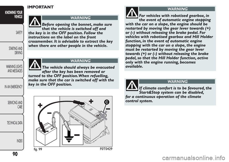
In the event of emergency starting fig. 99 with a
booster battery, never connect the negative lead (-)
of the booster battery to the negative pole C of
the vehicle's battery, but rather to an engine/gearbox
earth point (follow the lead connection procedure
described in the "Jump starting" paragraph in the
chapter "In an emergency").
fig. 97F0T0427fig. 98F0T0428
89
KNOWING YOUR
VEHICLE
SAFETY
STARTING AND
DRIVING
WARNING LIGHTS
AND MESSAGES
IN AN EMERGENCY
SERVICING AND
CARE
TECHNICAL DATA
INDEX
Page 94 of 260
IMPORTANT
WARNING
Before opening the bonnet , make sure
that the vehicle is switched off and
the key is in the OFF position. Follow the
instructions on the label on the front
crossmember. It is advisable to extract the key
when there are other people in the vehicle.
WARNING
The vehicle should always be evacuated
after the key has been removed or
turned to the OFF position.When refuelling,
make sure that the car is switched off with the
key in the OFF position.
WARNING
For vehicles with robotised gearbox, in
the event of automatic engine stopping
with the car on a slope, the engine should be
restarted by moving the gear lever towards (+)
or (-) without releasing the brake pedal. For
vehicles with robotised gearbox and Hill Holder
function, in the event of automatic engine
stopping with the car on a slope, the engine
must be restarted by moving the gear lever
towards (+) or (-) without releasing the brake
pedal, so that the Hill Holder function, active
only with the engine running, becomes
available.
WARNING
If climate comfort is to be favoured, the
Star t&Stop system can be disabled,
for a continuous operation of the climate
control system.
fig. 99F0T0429
90
KNOWING YOUR
VEHICLE
SAFETY
STARTING AND
DRIVING
WARNING LIGHTS
AND MESSAGES
IN AN EMERGENCY
SERVICING AND
CARE
TECHNICAL DATA
INDEX
Page 95 of 260
RADIO
(for versions/markets, where provided)
Read the Supplement attached to this Owner's
Handbook for the operation of the radio with
CD/MP3 player (for versions/markets, where
provided).
LIGHT SETUP
The system consists of:
radio power wires
speaker wires in front door panels
rear speaker wires (located next to parcel shelf )
(for versions/markets, where provided)
radio housing
antenna wires.
FULL SETUP
The system consists of:
radio power wires
speaker wires in front door panels
rear speaker wires (located next to parcel shelf )
(for versions/markets, where provided)
2 full-range Ø 130 mm placed in the door;
2 full-range speakers with Ø 100 mm placed on
the parcel shelf bracket (for versions / markets,
where provided);
radio housing
antenna wires
antenna.
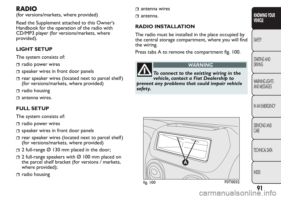
RADIO INSTALLATION
The radio must be installed in the place occupied by
the central storage compartment, where you will find
the wiring.
Press tabs A to remove the compartment fig. 100.
WARNING
To connect to the existing wiring in the
vehicle, contact a Fiat Dealership to
prevent any problems that could impair vehicle
safety.
fig. 100F0T0032
91
KNOWING YOUR
VEHICLE
SAFETY
STARTING AND
DRIVING
WARNING LIGHTS
AND MESSAGES
IN AN EMERGENCY
SERVICING AND
CARE
TECHNICAL DATA
INDEX
Page 96 of 260
INSTALLING ELECTRICAL/
ELECTRONIC DEVICES
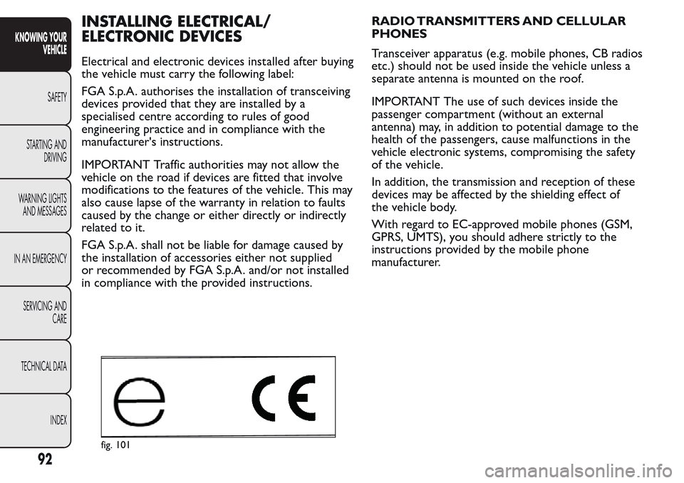
Electrical and electronic devices installed after buying
the vehicle must carry the following label:
FGA S.p.A. authorises the installation of transceiving
devices provided that they are installed by a
specialised centre according to rules of good
engineering practice and in compliance with the
manufacturer's instructions.
IMPORTANT Traffic authorities may not allow the
vehicle on the road if devices are fitted that involve
modifications to the features of the vehicle. This may
also cause lapse of the warranty in relation to faults
caused by the change or either directly or indirectly
related to it.
FGA S.p.A. shall not be liable for damage caused by
the installation of accessories either not supplied
or recommended by FGA S.p.A. and/or not installed
in compliance with the provided instructions.RADIO TRANSMITTERS AND CELLULAR
PHONES
Transceiver apparatus (e.g. mobile phones, CB radios
etc.) should not be used inside the vehicle unless a
separate antenna is mounted on the roof.
IMPORTANT The use of such devices inside the
passenger compartment (without an external
antenna) may, in addition to potential damage to the
health of the passengers, cause malfunctions in the
vehicle electronic systems, compromising the safety
of the vehicle.
In addition, the transmission and reception of these
devices may be affected by the shielding effect of
the vehicle body.
With regard to EC-approved mobile phones (GSM,
GPRS, UMTS), you should adhere strictly to the
instructions provided by the mobile phone
manufacturer.
fig. 101
92
KNOWING YOUR
VEHICLE
SAFETY
STARTING AND
DRIVING
WARNING LIGHTS
AND MESSAGES
IN AN EMERGENCY
SERVICING AND
CARE
TECHNICAL DATA
INDEX
Page 97 of 260
REFUELLING THE VEHICLE
PETROL ENGINES
Use unleaded petrol only, with octane number
(R.O.N.) not lower than 95.
IMPORTANT For the correct operation of the
engine, exclusively use metallic additive free fuels,
that can be recognised by the description “Metallic
Additive Free”. Furthermore, using even small
quantities of fuels with metallic additives, which can
be recognised by the description “Containing
metallic additive”, can irreparably damage the
catalytic converter.
IMPORTANT An inefficient catalytic converter leads
to harmful exhaust emissions, thus contributing to
air pollution.
IMPORTANT Never use leaded petrol, even in small
amounts or in an emergency, as this would damage
the catalytic converter beyond repair.
DIESEL ENGINES
Operation at low temperatures
If the outside temperature is very low, the diesel
thickens due to the formation of paraffin clots with
consequent defective operation of the fuel supply
system.
In order to avoid these problems, different types of
diesel are distributed according to the season:summer type, winter type and arctic type
(cold/mountain areas). If refuelling with diesel fuel
whose specifications are not suitable for the usage
temperature, it is advisable to mix TUTELA DIESEL
ART additive in the proportions shown on the
container with the fuel. Pour the additive into the
tank before the fuel.
When using or parking the vehicle for a long time in
the mountains or cold areas, it is advisable to refuel
using locally available diesel.
In this case, it is also advisable to keep the tank over
50% full.
For diesel engines, use only diesel fuel for
motor vehicles in accordance with EN590
European specifications.The use of other
products or mixtures may damage the engine
beyond repair and consequently invalidate the
warranty, due to the damage caused. If you
accidentally introduce other types of fuel into the
tank, do not start the engine. Empty the tank. If
the engine has been run for even an extremely
limited amount of time, you must not only drain
the fuel tank, but the rest of the supply circuit
as well.
93
KNOWING YOUR
VEHICLE
SAFETY
STARTING AND
DRIVING
WARNING LIGHTS
AND MESSAGES
IN AN EMERGENCY
SERVICING AND
CARE
TECHNICAL DATA
INDEX
Page 98 of 260
REFUELLING CAPACITY
To fill the tank completely, top up twice after the
first click of the trigger. Further top-ups could cause
faults in the fuel feeding system.
FUEL FILLER CAP
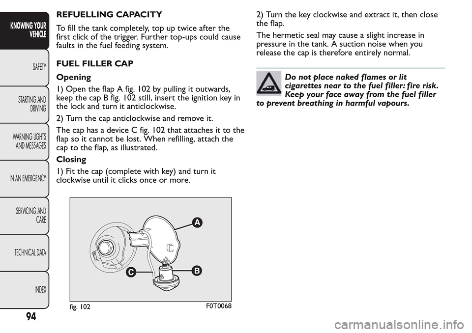
Opening
1) Open the flap A fig. 102 by pulling it outwards,
keep the cap B fig. 102 still, insert the ignition key in
the lock and turn it anticlockwise.
2) Turn the cap anticlockwise and remove it.
The cap has a device C fig. 102 that attaches it to the
flap so it cannot be lost. When refilling, attach the
cap to the flap, as illustrated.
Closing
1) Fit the cap (complete with key) and turn it
clockwise until it clicks once or more.2) Turn the key clockwise and extract it, then close
the flap.
The hermetic seal may cause a slight increase in
pressure in the tank. A suction noise when you
release the cap is therefore entirely normal.
Do not place naked flames or lit
cigarettes near to the fuel filler: fire risk.
Keep your face away from the fuel filler
to prevent breathing in harmful vapours.
fig. 102F0T0068
94
KNOWING YOUR
VEHICLE
SAFETY
STARTING AND
DRIVING
WARNING LIGHTS
AND MESSAGES
IN AN EMERGENCY
SERVICING AND
CARE
TECHNICAL DATA
INDEX
Page 99 of 260
FUEL CUT-OFF SYSTEM
This system is triggered after a collision as follows by:
the interruption of the fuel supply with the engine
consequently cutting out;
automatically unlocking the doors
turning on the lights inside the vehicle.
When the system has been triggered, the message
“Fuel cut off, see handbook” is displayed on some
versions.
Check carefully for fuel leaks, for instance in the
engine compartment, under the vehicle or near the
tank area.
After a crash, turn the ignition key to STOP to avoid
draining the battery.
The following procedure should be carried out to
restore the correct operation of the vehicle:
turn the ignition key to the ON position;
turn on the right direction indicator;
turn off the right direction indicator;
turn on the left direction indicator;
turn off the left direction indicator;
turn on the right direction indicator;
turn off the right direction indicator;
turn on the left direction indicator;
turn off the left direction indicator;
turn the ignition key to the OFF position.
WARNING
If, after an impact , you smell fuel or
notice leaks from the fuel system, do not
reactivate the system to avoid the risk of fire.
95
KNOWING YOUR
VEHICLE
SAFETY
STARTING AND
DRIVING
WARNING LIGHTS
AND MESSAGES
IN AN EMERGENCY
SERVICING AND
CARE
TECHNICAL DATA
INDEX
Page 100 of 260
PROTECTING THE ENVIRONMENT
The devices for reducing petrol engine emissions are
the following:
three-way catalytic converter
Lambda sensors
anti-evaporation system.
In addition, do not let the engine run, even for a test,
with one or more spark plugs disconnected.
The following devices are used for reducing diesel
fuel engine emissions:
oxidising catalytic converter
exhaust gas recirculation system (EGR)
diesel particulate filter (DPF) (for versions/
markets, where provided).
DIESEL PARTICULATE FILTER (DPF)
(for versions/markets, where provided)
The Diesel Particulate Filter is a mechanical filter,
integral to the exhaust system, that physically traps
carbon particulates present in the exhaust gases
of diesel engines.
It is needed to eliminate almost all particulates in
compliance with current/future legislation. During
normal use of the vehicle, the engine control unit
records a set of data (e.g.: travel time, type of route,
temperatures, etc.) and it will then calculate how
much particulate has been trapped by the filter.Since this filter physically traps particulate, it should
be regenerated (cleaned) at regular intervals by
burning the carbon particles. The regeneration
procedure is controlled automatically by the engine
management control unit according to the filter
conditions and vehicle use conditions.
During regeneration, the following may occur: a
limited increase in the engine speed, activation of the
fan, a limited increase in fumes and high
temperatures at the exhaust.
These are not faults; they do not impair vehicle
performance or damage the environment. If
the dedicated message is displayed, refer to the
“Warning lights and messages” section.
96
KNOWING YOUR
VEHICLE
SAFETY
STARTING AND
DRIVING
WARNING LIGHTS
AND MESSAGES
IN AN EMERGENCY
SERVICING AND
CARE
TECHNICAL DATA
INDEX