headlights FIAT QUBO 2017 1.G Owners Manual
[x] Cancel search | Manufacturer: FIAT, Model Year: 2017, Model line: QUBO, Model: FIAT QUBO 2017 1.GPages: 260, PDF Size: 4.74 MB
Page 20 of 260
FStart&Stop function indication (for versions/
markets, where provided).
GGear Shift Indication (for versions/markets, where
provided).
NoteWhen one of the front doors is opened, the
display is activated, showing the time and mileage for
a few seconds.
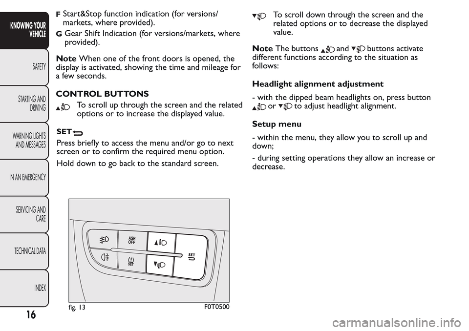
CONTROL BUTTONS
To scroll up through the screen and the related
options or to increase the displayed value.
SET
Press briefly to access the menu and/or go to next
screen or to confirm the required menu option.
Hold down to go back to the standard screen.
To scroll down through the screen and the
related options or to decrease the displayed
value.
NoteThe buttons
andbuttons activate
different functions according to the situation as
follows:
Headlight alignment adjustment
- with the dipped beam headlights on, press button
orto adjust headlight alignment.
Setup menu
- within the menu, they allow you to scroll up and
down;
- during setting operations they allow an increase or
decrease.
fig. 13F0T0500
16
KNOWING YOUR
VEHICLE
SAFETY
STARTING AND
DRIVING
WARNING LIGHTS
AND MESSAGES
IN AN EMERGENCY
SERVICING AND
CARE
TECHNICAL DATA
INDEX
Page 23 of 260
the changes already stored by the user (and
confirmed by pressing theSET
button briefly)
will be saved.
From the standard screen, press theSET
button
briefly to start browsing.
Press the
orbuttons to navigate within the
menu.
NoteOnly the reduced menu can be accessed while
the vehicle is moving for safety reasons ("Speed
Beep" setting). Stop the vehicle to access the full
menu.
Adjusting the vehicle interior lighting
This function is available with the dipped beam
headlights on to adjust brightness of the instrument
panel, buttons and radio display.
To adjust the light intensity, proceed as follows:
press the SETbutton briefly to make
the display flash the previously set level;
press theorbutton to set the required
brightness level;
press the SETbutton briefly to go back to the
menu screen or hold the button down to go back
to the standard screen without saving.
Speed limit (Speed Beep)
This function makes it possible to set the vehicle
speed limit (km/h or mph). When this limit isexceeded the driver is immediately alerted (see
“Warning lights and messages” section).
To set the desired speed limit, proceed as follows:
- press theSET
button briefly, the display will
show the wording (Speed Beep);
- press the
orbutton to select speed limit
activation (On) or deactivation (Off );
- if the function is on, press
orbutton to
select the desired speed limit and then pressSET
to confirm.
NoteSetting is possible between 30 and 200 km/h,
or 20 and 125 mph, according to the previously
set unit. See the "Setting the unit of measurement
(Measurement unit)" paragraph described below. The
setting will increase/decrease by 5 units each time
button
/is pressed. Hold down the/
button to automatically increase/decrease the
setting rapidly. Complete the adjustment with single
presses of the button when you approach the desired
value.
- press theSET
button briefly to go back to the
menu screen or hold the button down to go back
to the standard screen without saving.
To cancel the setting, proceed as follows:
- press theSET
button briefly to make the
display flash (On);
- press button
, (Off ) will flash on the display;
- press theSET
button briefly to go back to the
menu screen or hold the button down to go back
to the standard screen without saving.
19
KNOWING YOUR
VEHICLE
SAFETY
STARTING AND
DRIVING
WARNING LIGHTS
AND MESSAGES
IN AN EMERGENCY
SERVICING AND
CARE
TECHNICAL DATA
INDEX
Page 46 of 260
EXTERIOR LIGHTS
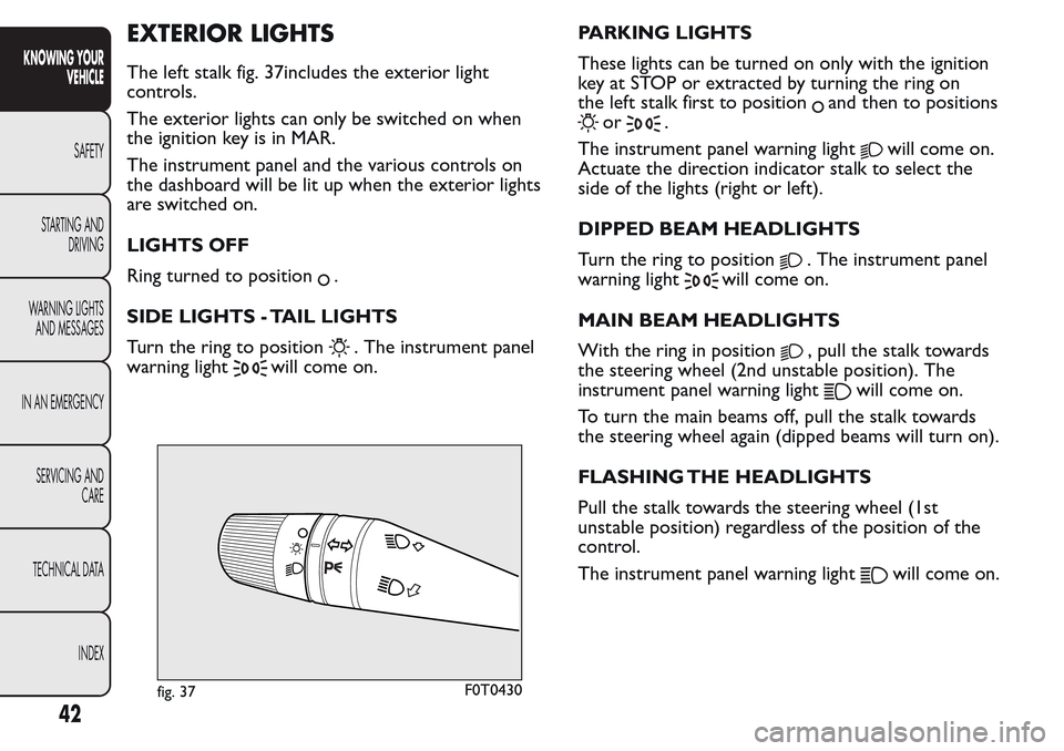
The left stalk fig. 37includes the exterior light
controls.
The exterior lights can only be switched on when
the ignition key is in MAR.
The instrument panel and the various controls on
the dashboard will be lit up when the exterior lights
are switched on.
LIGHTS OFF
Ring turned to position
.
SIDE LIGHTS - TAIL LIGHTS
Turn the ring to position
. The instrument panel
warning light
will come on.PARKING LIGHTS
These lights can be turned on only with the ignition
key at STOP or extracted by turning the ring on
the left stalk first to position
and then to positions
or.
The instrument panel warning light
will come on.
Actuate the direction indicator stalk to select the
side of the lights (right or left).
DIPPED BEAM HEADLIGHTS
Turn the ring to position
. The instrument panel
warning light
will come on.
MAIN BEAM HEADLIGHTS
With the ring in position
, pull the stalk towards
the steering wheel (2nd unstable position). The
instrument panel warning light
will come on.
To turn the main beams off, pull the stalk towards
the steering wheel again (dipped beams will turn on).
FLASHING THE HEADLIGHTS
Pull the stalk towards the steering wheel (1st
unstable position) regardless of the position of the
control.
The instrument panel warning light
will come on.
fig. 37F0T0430
42
KNOWING YOUR
VEHICLE
SAFETY
STARTING AND
DRIVING
WARNING LIGHTS
AND MESSAGES
IN AN EMERGENCY
SERVICING AND
CARE
TECHNICAL DATA
INDEX
Page 55 of 260
COMMANDS
HAZARD LIGHTS
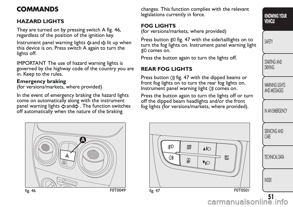
They are turned on by pressing switch A fig. 46,
regardless of the position of the ignition key.
Instrument panel warning lights
andlit up when
this device is on. Press switch A again to turn the
lights off.
IMPORTANT The use of hazard warning lights is
governed by the highway code of the country you are
in. Keep to the rules.
Emergency braking
(for versions/markets, where provided)
In the event of emergency braking the hazard lights
come on automatically along with the instrument
panel warning lights
and. The function switches
off automatically when the nature of the brakingchanges. This function complies with the relevant
legislations currently in force.
FOG LIGHTS
(for versions/markets, where provided)
Press button
fig. 47 with the side/taillights on to
turn the fog lights on. Instrument panel warning light
comes on.
Press the button again to turn the lights off.
REAR FOG LIGHTS
Press button
fig. 47 with the dipped beams or
front fog lights on to turn the rear fog lights on.
Instrument panel warning light
comes on.
Press the button again to turn the lights off or turn
off the dipped beam headlights and/or the front
fog lights (for versions/markets, where provided).
fig. 46F0T0049fig. 47F0T0501
51
KNOWING YOUR
VEHICLE
SAFETY
STARTING AND
DRIVING
WARNING LIGHTS
AND MESSAGES
IN AN EMERGENCY
SERVICING AND
CARE
TECHNICAL DATA
INDEX
Page 74 of 260
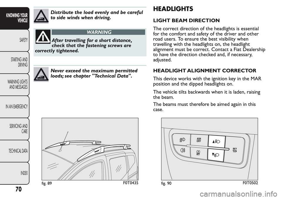
Distribute the load evenly and be careful
to side winds when driving.
WARNING
After travelling for a short distance,
check that the fastening screws are
correctly tightened.
Never exceed the maximum permitted
loads; see chapter "Technical Data".
HEADLIGHTS
LIGHT BEAM DIRECTION
The correct direction of the headlights is essential
for the comfort and safety of the driver and other
road users. To ensure the best visibility when
travelling with the headlights on, the headlight
alignment must be correct. Contact a Fiat Dealership
to have the direction checked and, if necessary,
adjusted.
HEADLIGHT ALIGNMENT CORRECTOR
This device works with the ignition key in the MAR
position and the dipped headlights on.
The vehicle tilts backwards when it is laden, raising
the beam.
The beams must therefore be aimed again in this
case.
fig. 89F0T0435fig. 90F0T0502
70
KNOWING YOUR
VEHICLE
SAFETY
STARTING AND
DRIVING
WARNING LIGHTS
AND MESSAGES
IN AN EMERGENCY
SERVICING AND
CARE
TECHNICAL DATA
INDEX
Page 75 of 260
Adjusting headlight alignment
Press the
orbuttons on the control
panelfig. 90.
The instrument panel display shows the position in
relation to the adjustment set.
Position 0 - one or two people in the front seats.
Position1-fivepeople.
Position2-fivepeople + load in the boot.
Position 3 - driver + maximum permitted load
stowed in the boot.
IMPORTANT Check the alignment of the light beams
each time the weight of the load transported
changes.
FOG LIGHT DIRECTION
(for versions/markets, where provided)
Contact a Fiat Dealership to have the direction
checked and, if necessary, adjusted.
ADJUSTING THE HEADLIGHTS WHEN
ABROAD
The dipped headlights are directed for operation in
the country where the vehicle was originally
purchased. In countries where you drive on the
other side of the road, you need to alter the beam
direction by affixing a specially designed self-adhesive
film in order not to dazzle the vehicles travelling in
the opposite direction.
ABS SYSTEM
This is an integral part of the braking system, which
prevents one or more wheels from locking or
slipping regardless of the road surface conditions and
braking intensity, giving the best control during
emergency braking.
The EBD system (Electronic Braking Force
Distribution) completes the system, allowing the
brake force to be distributed between the front and
rear wheels.
IMPORTANT For maximum efficiency of the braking
system, a bedding-in period of about 500 km is
needed: during this period it is better to avoid sharp,
repeated and prolonged braking.
SYSTEM INTERVENTION
The driver can tell the ABS system has come into
action because the brake pedal pulsates slightly and
the system gets noisier: it means that the vehicle
speed should be altered to suit the type of road
surface.
MECHANICAL BRAKE ASSIST (emergency
braking assistance)
(for versions/markets, where provided)
This system, which cannot be deactivated, recognises
emergency braking conditions (according to the
brake pedal operation speed) and provides an
additional hydraulic braking pressure to support that
71
KNOWING YOUR
VEHICLE
SAFETY
STARTING AND
DRIVING
WARNING LIGHTS
AND MESSAGES
IN AN EMERGENCY
SERVICING AND
CARE
TECHNICAL DATA
INDEX
Page 132 of 260
SAVING FUEL
Some useful tips are given below for fuel saving and
reducing harmful emissions of CO2 and other
pollutants (nitrogen oxides, unburnt hydrocarbons,
Particulate Matter (PM) etc.).
GENERAL CONSIDERATIONS
The general factors that affect fuel consumption are
listed below.
Vehicle maintenance
Have checks and adjustments carried out in
accordance with the “Scheduled Servicing Plan”.
Ty r e s
Check the tyre pressure at least once every four
weeks: if the pressure is too low, consumption levels
increase as resistance to rolling is higher.
Unnecessary loads
Do not travel with an overloaded boot. The weight
of the vehicle (especially when driving in town)
and its trim greatly affect fuel consumption
and stability.
Roof rack/ski rack
Remove the roof rack or the ski rack from the roof
after use. These accessories reduce the aerodynamic
coefficient of the vehicle and have a negative effecton fuel consumption. It is better to use a trailer to
transport particularly bulky objects.
Electric devices
Only use electrical devices for the amount of time
needed. The heated rear window, additional
headlights, windscreen/rear window wipers and
heater fan need a considerable amount of energy,
therefore increasing fuel consumption (by up to 25%
in the urban cycle).
Climate control system
The air conditioner leads to higher fuel consumption
(on average up to +20%). If the temperature outside
is not too extreme, try and use the air vents.
Spoilers
The use of non-certified spoilers may adversely affect
aerodynamics and fuel consumption.
128
KNOWING YOUR
VEHICLE
SAFETY
STARTING AND
DRIVING
WARNING LIGHTS
AND MESSAGES
IN AN EMERGENCY
SERVICING AND
CARE
TECHNICAL DATA
INDEX
Page 161 of 260
CHANGING A BULB
GENERAL INSTRUCTIONS
Before changing a bulb check the contacts for
oxidation;
burnt bulbs must be replaced by others of the
same type and power;
always check the height of the headlight beam
after changing a bulb, for reasons of safety;
when a light is not working, check that the
corresponding fuse is intact before changing the
bulb. For the location of fuses, refer to the
“Changing a fuse” paragraph in this section;
WARNING
Modifications or repairs to the electrical
system that are not carried out
properly or do not take the system's technical
specifications into account can cause
malfunctions leading to the risk of fire.
WARNING
Halogen bulbs contain pressurised gas
which may cause small fragments of
glass to be projected outwards if the bulb is
broken.
Halogen bulbs must be handled holding
the metallic part only.Touching the
transparent part of the bulb with your
fingers may reduce the intensity of the emitted
light and even reduce the lifespan of the bulb.
If you do touch it accidentally, rub the bulb with
an alcohol-soaked cloth and leave to dry.
If possible, we recommend have bulbs
replaced by a Fiat Dealership. Proper
operation and orientation of the external
lights are essential for the safety of the running
vehicle, and to avoid incurring legal sanctions.
IMPORTANT The internal surface of the light may
appear slightly misty: this does not indicate a fault,
and is actually caused by low temperature and the
degree of humidity in the air. Misting will rapidly
disappear when the headlights are switched on. The
presence of drops inside the headlights indicates
infiltration of water. Go to a Fiat Dealership.
157
KNOWING YOUR
VEHICLE
SAFETY
STARTING AND
DRIVING
WARNING LIGHTS
AND MESSAGES
IN AN
EMERGENCY
SERVICING AND
CARE
TECHNICAL DATA
INDEX
Page 164 of 260
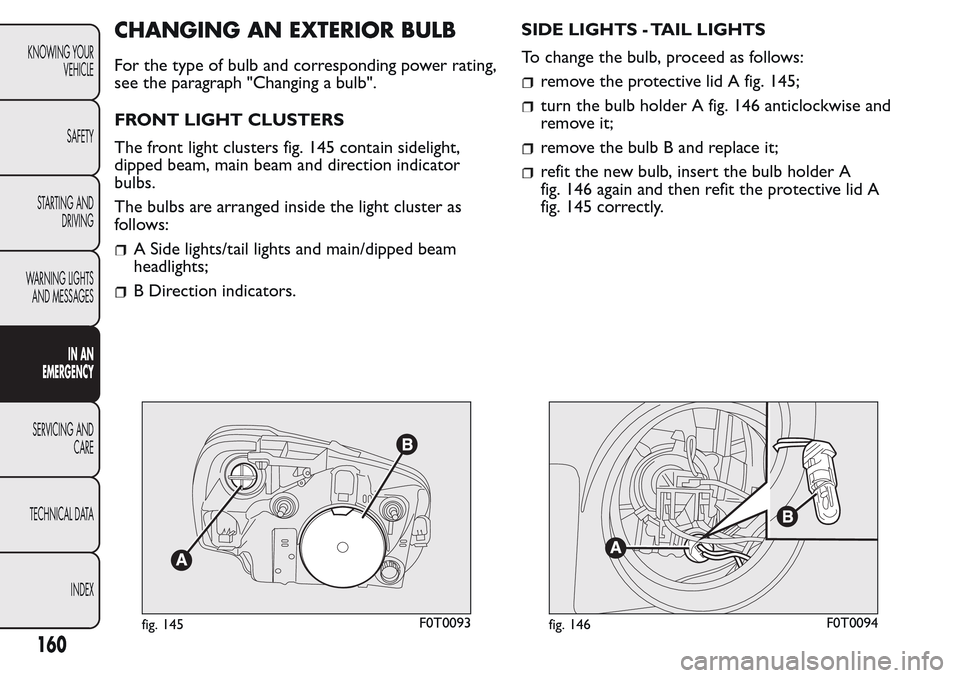
CHANGING AN EXTERIOR BULB
For the type of bulb and corresponding power rating,
see the paragraph "Changing a bulb".
FRONT LIGHT CLUSTERS
The front light clusters fig. 145 contain sidelight,
dipped beam, main beam and direction indicator
bulbs.
The bulbs are arranged inside the light cluster as
follows:
A Side lights/tail lights and main/dipped beam
headlights;
B Direction indicators.SIDE LIGHTS - TAIL LIGHTS
To change the bulb, proceed as follows:
remove the protective lid A fig. 145;
turn the bulb holder A fig. 146 anticlockwise and
remove it;
remove the bulb B and replace it;
refit the new bulb, insert the bulb holder A
fig. 146 again and then refit the protective lid A
fig. 145 correctly.
fig. 145F0T0093fig. 146F0T0094
160
KNOWING YOUR
VEHICLE
SAFETY
STARTING AND
DRIVING
WARNING LIGHTS
AND MESSAGES
IN AN
EMERGENCY
SERVICING AND
CARE
TECHNICAL DATA
INDEX
Page 165 of 260
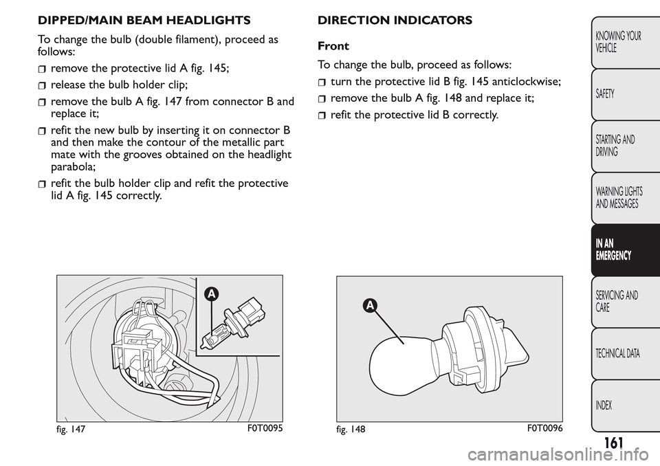
DIPPED/MAIN BEAM HEADLIGHTS
To change the bulb (double filament), proceed as
follows:
remove the protective lid A fig. 145;
release the bulb holder clip;
remove the bulb A fig. 147 from connector B and
replace it;
refit the new bulb by inserting it on connector B
and then make the contour of the metallic part
mate with the grooves obtained on the headlight
parabola;
refit the bulb holder clip and refit the protective
lid A fig. 145 correctly.DIRECTION INDICATORS
Front
To change the bulb, proceed as follows:
turn the protective lid B fig. 145 anticlockwise;
remove the bulb A fig. 148 and replace it;
refit the protective lid B correctly.
fig. 147F0T0095fig. 148F0T0096
161
KNOWING YOUR
VEHICLE
SAFETY
STARTING AND
DRIVING
WARNING LIGHTS
AND MESSAGES
IN AN
EMERGENCY
SERVICING AND
CARE
TECHNICAL DATA
INDEX