window FIAT SCUDO 2010 Owner handbook (in English)
[x] Cancel search | Manufacturer: FIAT, Model Year: 2010, Model line: SCUDO, Model: FIAT SCUDO 2010Pages: 210, PDF Size: 3.32 MB
Page 5 of 210
4
SAFETY
DEVICES
CORRECT USE
OF THE
VEHICLE
WARNING
LIGHTS AND
MESSAGES
IN AN
EMERGENCY
VEHICLE
MAINTENANCE
TECHNICAL
SPECIFICATIONS
INDEX
DASHBOARD
AND CONTROLSDASHBOARD ...................................................................... 5
SYMBOLS ............................................................................... 6
THE FIAT CODE SYSTEM ................................................. 6
THE KEYS .............................................................................. 7
ALARM ................................................................................... 10
IGNITION DEVICE ............................................................. 12
INSTRUMENT PANEL ........................................................ 13
INSTRUMENTS .................................................................... 14
DISPLAY.................................................................................. 15
MAINTENANCE INDICATOR ........................................ 16
TRIP COMPUTER................................................................. 17
FRONT SEATS ..................................................................... 17
REAR SEATS .......................................................................... 20
SEAT ARRANGEMENTS .................................................... 22
HEAD RESTRAINTS ........................................................... 23
STEERING WHEEL .............................................................. 24
REARVIEW MIRRORS ........................................................ 25
HEATING AND VENTILATION ..................................... 27
MANUAL CLIMATE CONTROL SYSTEM .................... 31
AUTOMATIC TWO-ZONE CLIMATE
CONTROL SYSTEM ........................................................... 37
AUTOMATIC THREE-ZONE CLIMATE
CONTROL SYSTEM ........................................................... 45
EXTERNAL LIGHTS ............................................................ 47WINDOW WASHING ...................................................... 50
CRUISE CONTROL SPEED REGULATOR.................... 54
“LIMIT” SPEED RESTRICTOR .......................................... 57
CEILING LIGHTS ................................................................. 60
CONTROLS .......................................................................... 61
FUEL CUT-OFF SWITCH .................................................. 64
INTERIOR EQUIPMENT..................................................... 65
DOORS .................................................................................. 69
SLIDING LUGGAGE COVER............................................ 73
POWER WINDOWS/WINDOW WINDERS .............. 74
BONNET ............................................................................... 76
ROOF RACK/SKI RACK .................................................... 77
PNEUMATIC SUSPENSIONS............................................. 78
LOAD RECOMMENDATIONS......................................... 79
HEADLIGHTS ....................................................................... 81
ABS SYSTEM ......................................................................... 82
ESP SYSTEM .......................................................................... 84
EOBD SYSTEM ..................................................................... 87
PARKING SENSORS ........................................................... 88
SOUND SYSTEM ................................................................. 89
ACCESSORIES PURCHASED BY THE OWNER ......... 90
AT THE FILLING STATION ............................................. 91
PROTECTING THE ENVIRONMENT ........................... 92
D D
A A
S S
H H
B B
O O
A A
R R
D D
A A
N N
D D
C C
O O
N N
T T
R R
O O
L L
S S
Page 6 of 210
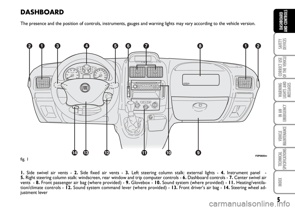
DASHBOARD
The presence and the position of controls, instruments, gauges and warning lights may vary according to the vehicle version.
1.Side swivel air vents - 2.Side fixed air vents - 3.Left steering column stalk: external lights - 4.Instrument panel -
5.Right steering column stalk: windscreen, rear window and trip computer controls - 6.Dashboard controls - 7.Center swivel air
vents - 8.Front passenger air bag (where provided) - 9.Glovebox - 10.Sound system (where provided) - 11.Heating/ventila-
tion/climate controls - 12.Sound system command lever (where provided) - 13.Front driver’s air bag - 14. Steering wheel ad-
justment lever
5
SAFETY
DEVICES
CORRECT USE
OF THE
VEHICLE
WARNING
LIGHTS AND
MESSAGES
IN AN
EMERGENCY
VEHICLE
MAINTENANCE
TECHNICAL
SPECIFICATIONS
INDEX
DASHBOARD
AND CONTROLS
F0P0600mfig. 1
Page 12 of 210
11
SAFETY
DEVICES
CORRECT USE
OF THE
VEHICLE
WARNING
LIGHTS AND
MESSAGES
IN AN
EMERGENCY
VEHICLE
MAINTENANCE
TECHNICAL
SPECIFICATIONS
INDEX
DASHBOARD
AND CONTROLS
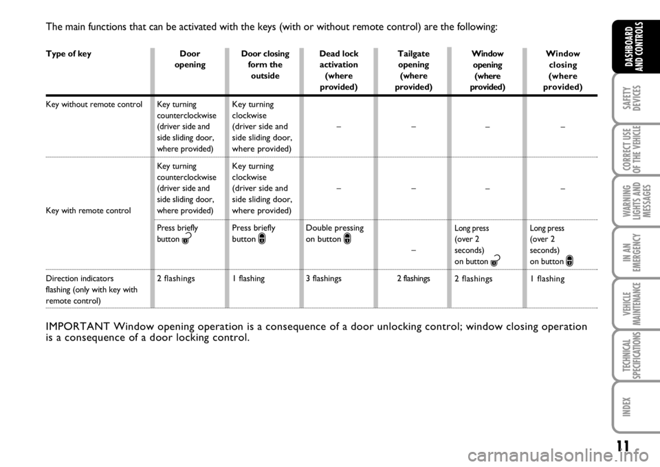
The main functions that can be activated with the keys (with or without remote control) are the following:
IMPORTANT Window opening operation is a consequence of a door unlocking control; window closing operation
is a consequence of a door locking control.
Type of key
Key without remote control
Key with remote control
Direction indicators
flashing (only with key with
remote control)Window
closing
(where
provided)
–
–
Long press(over 2
seconds)
on button
∫
1 flashing
Door
opening
Key turning
counterclockwise
(driver side and
side sliding door,
where provided)
Key turning
counterclockwise
(driver side and
side sliding door,
where provided)
Press briefly
button
ª
2 flashings
Door closing
form the
outside
Key turning
clockwise
(driver side and
side sliding door,
where provided)
Key turning
clockwise
(driver side and
side sliding door,
where provided)
Press briefly
button
∫
1 flashing
Dead lock
activation
(where
provided)
–
–
Double pressing
on button
∫
3 flashings
Tailgate
opening
(where
provided)
–
–
–
2 flashings
Window
opening
(where
provided)
–
–
Long press(over 2
seconds)
on button
ª
2 flashings
Page 29 of 210
28
SAFETY
DEVICES
CORRECT USE
OF THE
VEHICLE
WARNING
LIGHTS AND
MESSAGES
IN AN
EMERGENCY
VEHICLE
MAINTENANCE
TECHNICAL
SPECIFICATIONS
INDEX
DASHBOARD
AND
CONTROLS
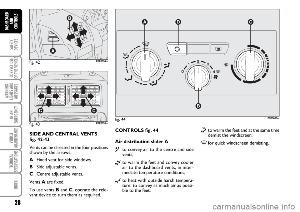
CONTROLS fig. 44
Air distribution slider A
µto convey air to the centre and side
vents;
∑to warm the feet and convey cooler
air to the dashboard vents, in inter-
mediate temperature conditions;
∂to heat with outside harsh tempera-
ture: to convey as much air as possi-
ble to the feet;
∏to warm the feet and at the same time
demist the windscreen;
-for quick windscreen demisting.
fig. 44F0P0036m
fig. 42F0P0034m
fig. 43F0P0035m
SIDE AND CENTRAL VENTS
fig. 42-43
Vents can be directed in the four positions
shown by the arrows.
AFixed vent for side windows.
BSide adjustable vents.
CCentre adjustable vents.
Vents Aare fixed.
To use vents Band C, operate the rele-
vant device to turn them as required.
Page 31 of 210
30
SAFETY
DEVICES
CORRECT USE
OF THE
VEHICLE
WARNING
LIGHTS AND
MESSAGES
IN AN
EMERGENCY
VEHICLE
MAINTENANCE
TECHNICAL
SPECIFICATIONS
INDEX
DASHBOARD
AND
CONTROLS
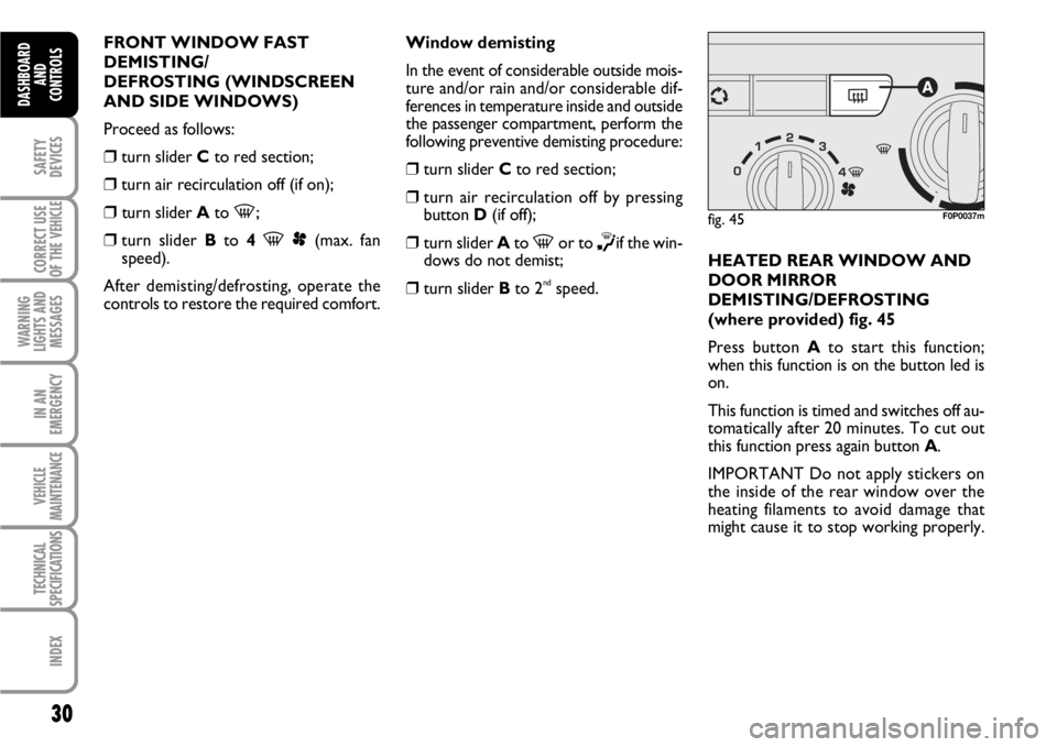
FRONT WINDOW FAST
DEMISTING/
DEFROSTING (WINDSCREEN
AND SIDE WINDOWS)
Proceed as follows:
❒turn slider Cto red section;
❒turn air recirculation off (if on);
❒turn slider Ato -;
❒
turn slider Bto 4 -p(max. fan
speed).
After demisting/defrosting, operate the
controls to restore the required comfort.Window demisting
In the event of considerable outside mois-
ture and/or rain and/or considerable dif-
ferences in temperature inside and outside
the passenger compartment, perform the
following preventive demisting procedure:
❒turn slider Cto red section;
❒turn air recirculation off by pressing
button D(if off);
❒turn slider Ato -or to ∏if the win-
dows do not demist;
❒turn slider Bto 2ndspeed.HEATED REAR WINDOW AND
DOOR MIRROR
DEMISTING/DEFROSTING
(where provided) fig. 45
Press button Ato start this function;
when this function is on the button led is
on.
This function is timed and switches off au-
tomatically after 20 minutes. To cut out
this function press again button A.
IMPORTANT Do not apply stickers on
the inside of the rear window over the
heating filaments to avoid damage that
might cause it to stop working properly.
fig. 45F0P0037m
Page 35 of 210

34
SAFETY
DEVICES
CORRECT USE
OF THE
VEHICLE
WARNING
LIGHTS AND
MESSAGES
IN AN
EMERGENCY
VEHICLE
MAINTENANCE
TECHNICAL
SPECIFICATIONS
INDEX
DASHBOARD
AND
CONTROLS
HEATING
Proceed as follows:
❒turn slider Cto red section;
❒turn slider Ato the required symbol;
❒turn slider Bto the required speed;FAST HEATING
For fast heating of the passenger com-
partment, proceed as follows:
❒turn slider Cto red section;
❒turn air recirculation on by pressing
button D (if off);
❒turn slider Ato ∂;
❒turn slider Bto 4-p(max. fan
speed).
Then use the controls to keep the re-
quired comfort conditions and press but-
ton Dto turn air recirculation off.
IMPORTANT With cold engine, you have
to wait for a few minutes to let the sys-
tem fluid reach the operating temperature.FRONT WINDOW FAST
DEMISTING/
DEFROSTING (WINDSCREEN
AND SIDE WINDOWS)
Proceed as follows:
❒turn slider Cto red section;
❒turn slider Bto 4-p(max. fan
speed);
❒turn slider Ato -.
❒turn air recirculation off by pressing
button D(if on).
Page 36 of 210
35
SAFETY
DEVICES
CORRECT USE
OF THE
VEHICLE
WARNING
LIGHTS AND
MESSAGES
IN AN
EMERGENCY
VEHICLE
MAINTENANCE
TECHNICAL
SPECIFICATIONS
INDEX
DASHBOARD
AND CONTROLS
Window demisting
In the event of considerable outside mois-
ture and/or rain and/or considerable dif-
ferences in temperature inside and outside
the passenger compartment, perform the
following preventive demisting procedure:
❒turn slider Cto red section;
❒turn air recirculation off by pressing
button D(if on);
❒turn slider Ato -or to ®if the win-
dows do not demist;
❒turn slider Bto 2ndspeed.
IMPORTANT The climate control system
is very useful to prevent window misting
up in presence of high humidity since it de-
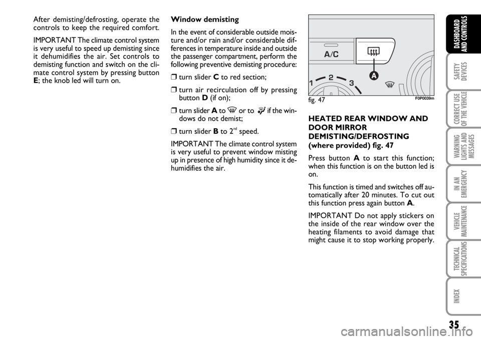
humidifies the air.HEATED REAR WINDOW AND
DOOR MIRROR
DEMISTING/DEFROSTING
(where provided) fig. 47
Press button Ato start this function;
when this function is on the button led is
on.
This function is timed and switches off au-
tomatically after 20 minutes. To cut out
this function press again button A.
IMPORTANT Do not apply stickers on
the inside of the rear window over the
heating filaments to avoid damage that
might cause it to stop working properly.
fig. 47F0P0039m
After demisting/defrosting, operate the
controls to keep the required comfort.
IMPORTANT The climate control system
is very useful to speed up demisting since
it dehumidifies the air. Set controls to
demisting function and switch on the cli-
mate control system by pressing button
E; the knob led will turn on.
Page 38 of 210

37
SAFETY
DEVICES
CORRECT USE
OF THE
VEHICLE
WARNING
LIGHTS AND
MESSAGES
IN AN
EMERGENCY
VEHICLE
MAINTENANCE
TECHNICAL
SPECIFICATIONS
INDEX
DASHBOARD
AND CONTROLS
AUTOMATIC TWO-ZONE
CLIMATE CONTROL
SYSTEM
(where provided)
DESCRIPTION
The vehicle is fitted with a two-zone cli-
mate control system which makes it pos-
sible to separately adjust the air temper-
atures and air distribution on the driver’s
side and on the passenger’s side.
Temperature control is based on the
“equivalent temperature” logic, i.e.: the
system continuously works to keep con-
stant the comfort inside the passenger
compartment and to compensate any vari-
ation of the outside climate conditions, in-
cluding sunshine detected by a proper sen-
sor provided for the purpose.
The climate control system automatically
controls and adjusts the following para-
meters and functions:
❒air temperature at driver/front passen-
ger vents;
❒air distribution at driver/front passen-
ger vents;
❒fan speed (continuous air flow variation);
❒compressor activation (to cool/dehu-
midify air);
❒air recirculation.All the above functions can be changed
manually by selecting the required func-
tion/s and by changing the set parameters.
In this way the automatic control is de-
activated; the system will resume auto-
matic control only for safety reasons.
Manual selections prevail over automatic
ones and remain in storage until the user
decides to resume automatic control
(press button AUTO, except when the
system cuts in for particular safety condi-
tions. The control of functions not
changed manually remains automatic.
The amount of air admitted to the pas-
senger compartment does not depend on
the vehicle speed, since it is electronical-
ly controlled by the fan. The temperature
of the air admitted to the passenger com-
partment is always controlled automati-
cally according to the temperatures set on
the driver’s and front passenger’s display
(except when the system is off or under
certain conditions when the compressor
is off).The following parameters and functions
can be set or changed manually:
❒ air temperatures on driver/front pas-
senger side;
❒ fan speed (continuous variation);
❒air distribution on seven levels (dri-
ver/front passenger side);
❒ climate control compressor on/off en-
able;
❒monozone/two-zone distribution prior-
ity;
❒ fast demisting/defrosting;
❒ air recirculation;
❒ rear heated window;
❒system deactivation.
Page 39 of 210
38
SAFETY
DEVICES
CORRECT USE
OF THE
VEHICLE
WARNING
LIGHTS AND
MESSAGES
IN AN
EMERGENCY
VEHICLE
MAINTENANCE
TECHNICAL
SPECIFICATIONS
INDEX
DASHBOARD
AND
CONTROLS
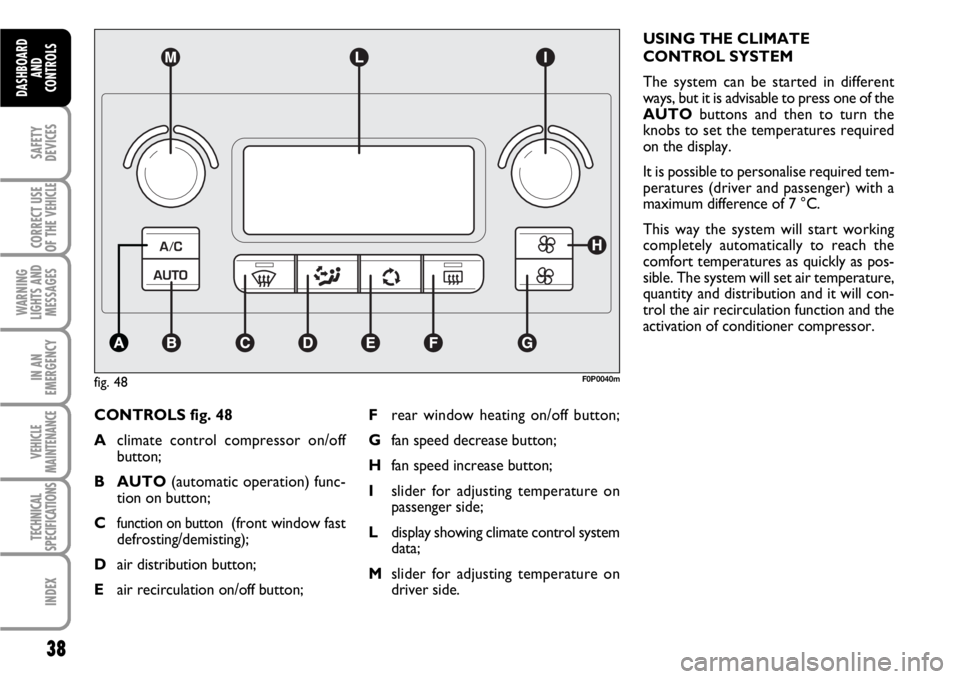
CONTROLS fig. 48
Aclimate control compressor on/off
button;
B AUTO(automatic operation) func-
tion on button;
C
function on button (front window fast
defrosting/demisting);
Dair distribution button;
Eair recirculation on/off button;USING THE CLIMATE
CONTROL SYSTEM
The system can be started in different
ways, but it is advisable to press one of the
AUTObuttons and then to turn the
knobs to set the temperatures required
on the display.
It is possible to personalise required tem-
peratures (driver and passenger) with a
maximum difference of 7 °C.
This way the system will start working
completely automatically to reach the
comfort temperatures as quickly as pos-
sible. The system will set air temperature,
quantity and distribution and it will con-
trol the air recirculation function and the
activation of conditioner compressor.
fig. 48F0P0040m
Frear window heating on/off button;
Gfan speed decrease button;
Hfan speed increase button;
Islider for adjusting temperature on
passenger side;
Ldisplay showing climate control system
data;
Mslider for adjusting temperature on
driver side.
Page 40 of 210

39
SAFETY
DEVICES
CORRECT USE
OF THE
VEHICLE
WARNING
LIGHTS AND
MESSAGES
IN AN
EMERGENCY
VEHICLE
MAINTENANCE
TECHNICAL
SPECIFICATIONS
INDEX
DASHBOARD
AND CONTROLS
During fully automatic operation, the on-
ly manual settings required are the fol-
lowing:
❒Ωair recirculation, to keep it always
on or off;
❒-to speed up demisting/defrosting
of windscreen, side windows, rear win-
dow and door mirrors;
❒(to demist/defrost heated rear win-
dow and door mirrors;
❒πto select air distribution during ven-
tilation.
During full automatic system operation,
you can change at any time set tempera-
tures, air distribution and fan speed by us-
ing the relevant buttons or knobs: the sys-
tem will automatically change its settings
to adjust to the new requirements.Air temperature adjusting knobs
M - I
Turning the knobs clockwise or counter-
clockwise, respectively increases or de-
creases the temperature of the air required
respectively in the front left zone (knob M)
and in the right zone (knob I) f the passen-
ger compartment. Since the system controls
two zones of the passenger compartment,
it is possible to personalise required tem-
peratures (driver and passenger) with a
maximum difference of 7 °C.
The temperatures set are shown on the dis-
play near the relevant knobs. Pressing but-
ton AUTOwill activate automatic opera-
tion in order to have two separate ventila-
tion temperatures between driver and pas-
senger’s side.
With automatic operation on, pressing again
button AUTOwill align the temperature
on the passenger’s side with that on the dri-
ver’s side.
Turn the knobs fully clockwise or counter-
clockwise to engage respectively HI(max-
imum heating) or LO(maximum cooling).
To deactivate these two functions, just
turn the temperature knob and set the re-
quired temperature.Front air distribution button D
Pressing this button it is possible to
choose manually one of the seven possi-
ble air distributions to the passenger com-
partment (right or left side):
æAir flow to the windscreen and front
side window vents to demist or de-
frost them.
øAir flow at central and side dash-
board vents to ventilate the chest and
the face during the hot season.
¿Air flow towards the front and rear
lower parts of the passenger com-
partment. Due to the natural ten-
dency of heat to spread upwards, this
type of distribution allows heating of
the passenger compartment in the
shortest time, also giving a prompt
feeling of warmth.