lock FIAT SCUDO 2012 Owner handbook (in English)
[x] Cancel search | Manufacturer: FIAT, Model Year: 2012, Model line: SCUDO, Model: FIAT SCUDO 2012Pages: 219, PDF Size: 4.13 MB
Page 146 of 219
142
WARNING
LIGHTS AND
MESSAGES
VEHICLE
MAINTENANCE
TECHNICAL
SPECIFICATIONS
INDEX
DASHBOARD
AND CONTROLS
SAFETY
DEVICES
CORRECT USE
OF THE
VEHICLE
IN AN
EMERGENCY
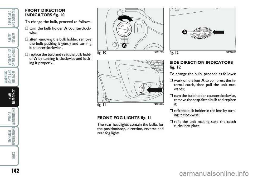
FRONT DIRECTION
INDICATORS fig. 10
To change the bulb, proceed as follows:
❒turn the bulb holder Acounterclock-
wise;
❒after removing the bulb holder, remove
the bulb pushing it gently and turning
it counterclockwise .
❒replace the bulb and refit the bulb hold-
er Aby turning it clockwise and lock-
ing it properly.
FRONT FOG LIGHTS fig. 11
The rear headlights contain the bulbs for
the position/stop, direction, reverse and
rear fog lights.SIDE DIRECTION INDICATORS
fig. 12
To change the bulb, proceed as follows:
❒work on the lens Ato compress the in-
ternal catch, then pull the unit out-
wards;
❒turn the bulb holder counterclockwise,
remove the snap-fitted bulb and replace
it;
❒refit the bulb holder in the lens by turn-
ing it clockwise;
❒refit the unit making sure the catch
clicks into place.
fig. 11F0P0181m
fig. 10F0P0179mfig. 12
A
F0P0297m
Page 147 of 219
143
WARNING
LIGHTS AND
MESSAGES
VEHICLE
MAINTENANCE
TECHNICAL
SPECIFICATIONS
INDEX
DASHBOARD
AND CONTROLS
SAFETY
DEVICES
CORRECT USE
OF THE
VEHICLE
IN AN
EMERGENCY
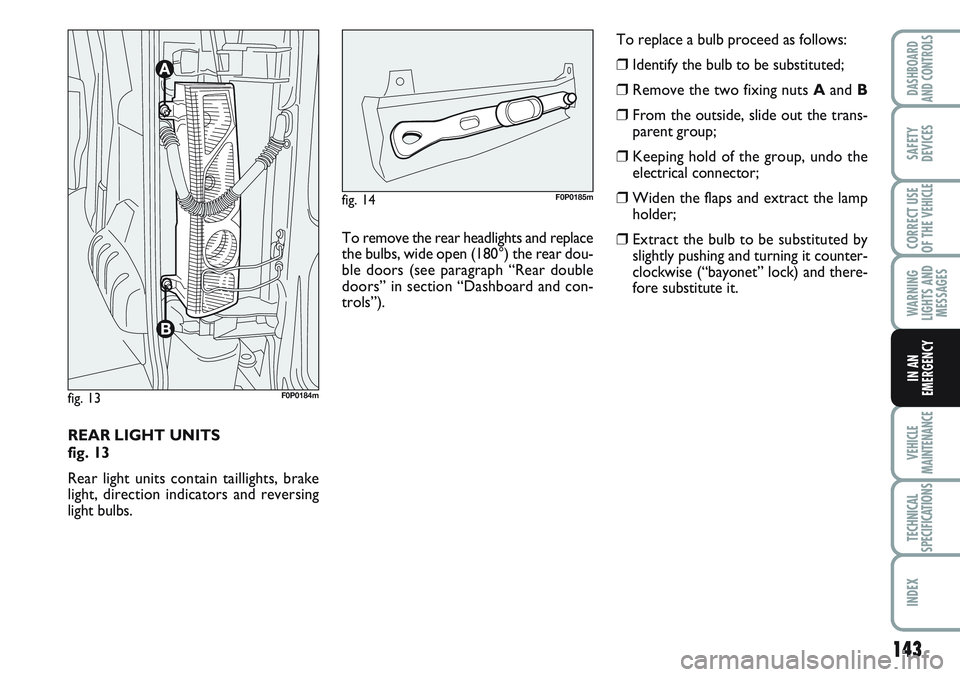
REAR LIGHT UNITS
fig. 13
Rear light units contain taillights, brake
light, direction indicators and reversing
light bulbs.
fig. 13F0P0184m
To remove the rear headlights and replace
the bulbs, wide open (180°) the rear dou-
ble doors (see paragraph “Rear double
doors” in section “Dashboard and con-
trols”).
fig. 14F0P0185m
To replace a bulb proceed as follows:
❒Identify the bulb to be substituted;
❒Remove the two fixing nuts Aand B
❒From the outside, slide out the trans-
parent group;
❒Keeping hold of the group, undo the
electrical connector;
❒Widen the flaps and extract the lamp
holder;
❒Extract the bulb to be substituted by
slightly pushing and turning it counter-
clockwise (“bayonet” lock) and there-
fore substitute it.
Page 149 of 219
145
WARNING
LIGHTS AND
MESSAGES
VEHICLE
MAINTENANCE
TECHNICAL
SPECIFICATIONS
INDEX
DASHBOARD
AND CONTROLS
SAFETY
DEVICES
CORRECT USE
OF THE
VEHICLE
IN AN
EMERGENCY
IF AN INTERIOR BULB
BURNS OUT
For the type of bulb and power rating, see
paragraph “When needing to change a
bulb”.
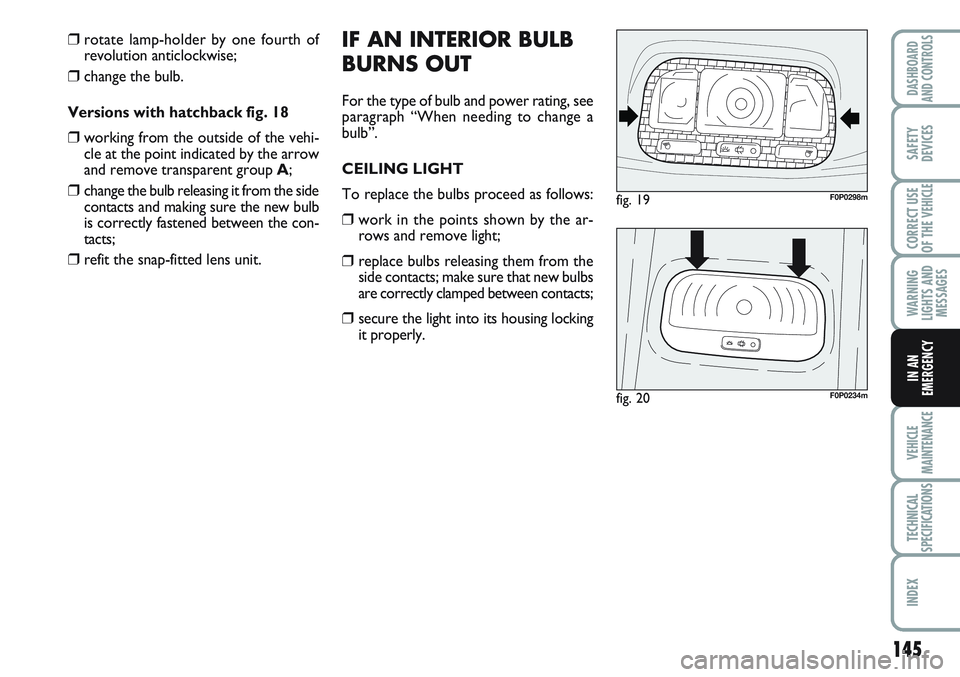
CEILING LIGHT
To replace the bulbs proceed as follows:
❒work in the points shown by the ar-
rows and remove light;
❒replace bulbs releasing them from the
side contacts; make sure that new bulbs
are correctly clamped between contacts;
❒secure the light into its housing locking
it properly.
fig. 19F0P0298m
fig. 20F0P0234m
❒rotate lamp-holder by one fourth of
revolution anticlockwise;
❒change the bulb.
Versions with hatchback fig. 18
❒working from the outside of the vehi-
cle at the point indicated by the arrow
and remove transparent group A;
❒change the bulb releasing it from the side
contacts and making sure the new bulb
is correctly fastened between the con-
tacts;
❒refit the snap-fitted lens unit.
Page 151 of 219
147
WARNING
LIGHTS AND
MESSAGES
VEHICLE
MAINTENANCE
TECHNICAL
SPECIFICATIONS
INDEX
DASHBOARD
AND CONTROLS
SAFETY
DEVICES
CORRECT USE
OF THE
VEHICLE
IN AN
EMERGENCY
fig. 22F0P0299m
F1
F2
F4
F5
F6
F7
F8
F9
F10
F11
F12
F13
F14
F15
F16
F1715
–
10
30
30
5
20
10
30
15
15
5
15
30
–
40
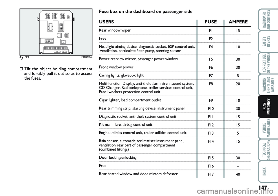
Fuse box on the dashboard on passenger side
USERS FUSE AMPERE
Rear window wiper
Free
Headlight aiming device, diagnostic socket, ESP control unit,
ventilation, particulate filter pump, steering sensor
Power rearview mirror, passenger power window
Front window power
Ceiling lights, glovebox light
Multi-function Display, anti-theft alarm siren, sound system,
CD-Changer, Radiotelephone, trailer services control unit,
Panel workers protection control unit
Cigar lighter, load compartment outlet
Rear trimming strip, starting device, instrument panel
Diagnostic socket, anti-theft system control unit
Kit main libre, airbag control unit
Engine utilities control unit, trailer utilities control unit
Rain sensor, automatic acclimatiser instrument panel,
ventilation rear part of passenger compartment
(combined fittings)
Door locking/unlocking
Free
Rear heated window and door mirrors defroster
❒Tilt the object holding compartment
and forcibly pull it out so as to access
the fuses.
Page 153 of 219
149
WARNING
LIGHTS AND
MESSAGES
VEHICLE
MAINTENANCE
TECHNICAL
SPECIFICATIONS
INDEX
DASHBOARD
AND CONTROLS
SAFETY
DEVICES
CORRECT USE
OF THE
VEHICLE
IN AN
EMERGENCY
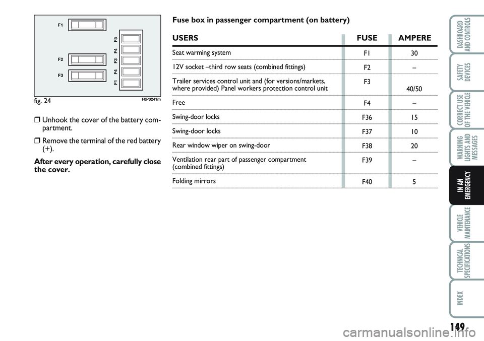
fig. 24
F1
F2
F3
F1 F4 F3 F4 F5
F0P0241m
F1
F2
F3
F4
F36
F37
F38
F39
F4030
–
40/50
–
15
10
20
–
5
Fuse box in passenger compartment (on battery)
USERS FUSE AMPERE
Seat warming system
12V socket –third row seats (combined fittings)
Trailer services control unit and (for versions/markets,
where provided) Panel workers protection control unit
Free
Swing-door locks
Swing-door locks
Rear window wiper on swing-door
Ventilation rear part of passenger compartment
(combined fittings)
Folding mirrors
❒Unhook the cover of the battery com-
partment.
❒Remove the terminal of the red battery
(+).
After every operation, carefully close
the cover.
Page 156 of 219
152
WARNING
LIGHTS AND
MESSAGES
VEHICLE
MAINTENANCE
TECHNICAL
SPECIFICATIONS
INDEX
DASHBOARD
AND CONTROLS
SAFETY
DEVICES
CORRECT USE
OF THE
VEHICLE
IN AN
EMERGENCY
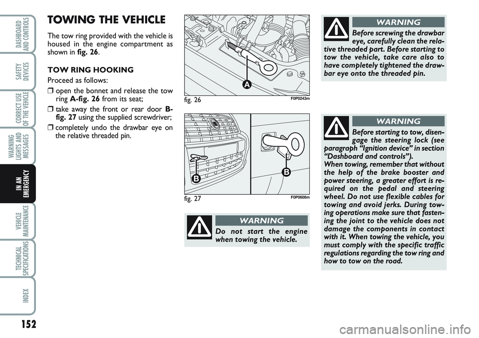
fig. 26
A
F0P0243m
Do not start the engine
when towing the vehicle.
WARNING
Before screwing the drawbar
eye, carefully clean the rela-
tive threaded part. Before starting to
tow the vehicle, take care also to
have completely tightened the draw-
bar eye onto the threaded pin.
WARNING
Before starting to tow, disen-
gage the steering lock (see
paragraph “Ignition device” in section
“Dashboard and controls”).
When towing, remember that without
the help of the brake booster and
power steering, a greater effort is re-
quired on the pedal and steering
wheel. Do not use flexible cables for
towing and avoid jerks. During tow-
ing operations make sure that fasten-
ing the joint to the vehicle does not
damage the components in contact
with it. When towing the vehicle, you
must comply with the specific traffic
regulations regarding the tow ring and
how to tow on the road.
WARNING
fig. 27F0P0608m
TOWING THE VEHICLE
The tow ring provided with the vehicle is
housed in the engine compartment as
shown in fig. 26.
TOW RING HOOKING
Proceed as follows:
❒open the bonnet and release the tow
ring A-fig. 26from its seat;
❒take away the front or rear door B-
fig. 27using the supplied screwdriver;
❒completely undo the drawbar eye on
the relative threaded pin.
Page 159 of 219
155
WARNING
LIGHTS AND
MESSAGES
TECHNICAL
SPECIFICATIONS
INDEX
DASHBOARD
AND CONTROLS
SAFETY
DEVICES
CORRECT USE
OF THE
VEHICLE
IN AN
EMERGENCY
VEHICLE
MAINTENANCE
30 60 90 120 150 180
●●●●● ●
●●●●● ●
●●●●● ●
●●●●● ●
●●●●● ●
●● ●
●●●●● ●
●●
●●●●● ●
●●●●● ●
●●●●● ●
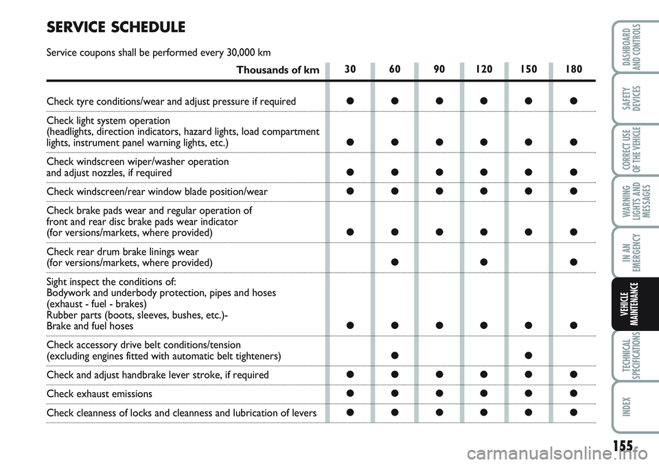
SERVICE SCHEDULE
Service coupons shall be performed every 30,000 km
Thousands of km
Check tyre conditions/wear and adjust pressure if required
Check light system operation
(headlights, direction indicators, hazard lights, load compartment
lights, instrument panel warning lights, etc.)
Check windscreen wiper/washer operation
and adjust nozzles, if required
Check windscreen/rear window blade position/wear
Check brake pads wear and regular operation of
front and rear disc brake pads wear indicator
(for versions/markets, where provided)
Check rear drum brake linings wear
(for versions/markets, where provided)
Sight inspect the conditions of:
Bodywork and underbody protection, pipes and hoses
(exhaust - fuel - brakes)
Rubber parts (boots, sleeves, bushes, etc.)-
Brake and fuel hoses
Check accessory drive belt conditions/tension
(excluding engines fitted with automatic belt tighteners)
Check and adjust handbrake lever stroke, if required
Check exhaust emissions
Check cleanness of locks and cleanness and lubrication of levers
Page 161 of 219
157
WARNING
LIGHTS AND
MESSAGES
TECHNICAL
SPECIFICATIONS
INDEX
DASHBOARD
AND CONTROLS
SAFETY
DEVICES
CORRECT USE
OF THE
VEHICLE
IN AN
EMERGENCY
VEHICLE
MAINTENANCE
HEAVY-DUTY
Should prevailing use of the vehicle be un-
der one of the following specially heavy
conditions:
❒trailer or caravan towing;
❒dusty roads;
❒short distances (less than 7-8 km) re-
peated and with external tempera-
tures below zero;
❒frequently idling engines or long dis-
tance low speed driving (e.g. door-to-
door deliveries) or in case of a long
term inactivity;
❒driving in the city;
carry out the following checks more fre-
quently than required in the Service
Schedule:
❒check front disk brake pad conditions
and wear;
❒check cleanness of locks, bonnet and
boot and lever cleanness and lubrica-
tion;
❒sight inspect the conditions of: engine,
gearbox, transmission, pipes and hoses
(exhaust - fuel - brakes), rubber parts
(boots, sleeves, bushes, etc.);
❒check battery charge and fluid level
(electrolyte);
❒visual check on various drive belt con-
ditions;
❒check and replace pollen filter, if re-
quired;
❒check and replace air cleaner, if re-
quired.
ROUTINE
MAINTENANCE
Every 1,000 km or before long journeys,
check and top up if required:
❒engine coolant fluid level;
❒brake fluid level;
❒windscreen washer fluid level;
❒tyre pressure and conditions;
❒light system operation (headlights, di-
rection indicators, hazard lights, etc.);
❒windscreen wiper/washer operation
and windscreen/rear window blade
position/wear;
Every 3,000 km check and top up if re-
quired: engine oil level.
You are recommended to use PETRO-
NAS LUBRICANTS, products, designed
and produced specifically for Fiat vehicles
(see table “Capacities” in section “Tech-
nical specifications”).
Page 173 of 219
169
WARNING
LIGHTS AND
MESSAGES
TECHNICAL
SPECIFICATIONS
INDEX
DASHBOARD
AND CONTROLS
SAFETY
DEVICES
CORRECT USE
OF THE
VEHICLE
IN AN
EMERGENCY
VEHICLE
MAINTENANCE
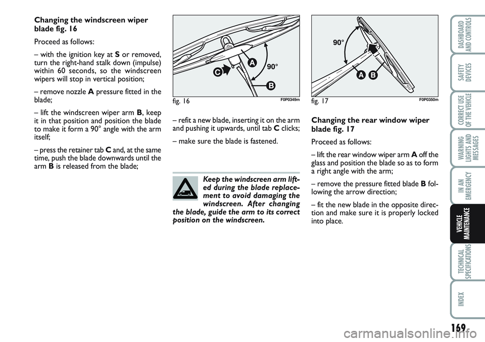
Changing the windscreen wiper
blade fig. 16
Proceed as follows:
– with the ignition key at Sor removed,
turn the right-hand stalk down (impulse)
within 60 seconds, so the windscreen
wipers will stop in vertical position;
– remove nozzle Apressure fitted in the
blade;
– lift the windscreen wiper arm B, keep
it in that position and position the blade
to make it form a 90° angle with the arm
itself;
– press the retainer tab Cand, at the same
time, push the blade downwards until the
arm Bis released from the blade;– refit a new blade, inserting it on the arm
and pushing it upwards, until tab Cclicks;
– make sure the blade is fastened.Changing the rear window wiper
blade fig. 17
Proceed as follows:
– lift the rear window wiper arm Aoff the
glass and position the blade so as to form
a right angle with the arm;
– remove the pressure fitted blade Bfol-
lowing the arrow direction;
– fit the new blade in the opposite direc-
tion and make sure it is properly locked
into place. Keep the windscreen arm lift-
ed during the blade replace-
ment to avoid damaging the
windscreen. After changing
the blade, guide the arm to its correct
position on the windscreen.
fig. 16F0P0349mfig. 17F0P0350m
Page 176 of 219
172
WARNING
LIGHTS AND
MESSAGES
TECHNICAL
SPECIFICATIONS
INDEX
DASHBOARD
AND CONTROLS
SAFETY
DEVICES
CORRECT USE
OF THE
VEHICLE
IN AN
EMERGENCY
VEHICLE
MAINTENANCE
Fabric upholstery of your ve-
hicle is purpose-made to
withstand common wear re-
sulting from normal use of the
vehicle. It is however absolutely neces-
sary to prevent hard and/or prolonged
scratching/scraping caused by clothing
accessories like metallic buckles, studs,
“Velcro” fixings, etc. that stressing lo-
cally the fabric could break yarns and
damage the upholstery as a conse-
quence. CLEANING SEATS
AND FABRICS
Remove dust with a soft brush and vacu-
um cleaner. For velvet seats use a damp
brush.
Rub the seats with a sponge moistened
with a solution of water and neutral de-
tergent.Never use flammable prod-
ucts like oil ether or rectified
petrol for cleaning vehicle interiors.
Electrostatic discharges generated by
rubbing during cleaning operations
could cause fire.
WARNING
Do not keep aerosol cans in
the vehicle: they might ex-
plode. Aerosol cans must never be ex-
posed to a temperature above 50° C.
The temperature inside the vehicle
exposed to the sun may go well be-
yond that figure.
WARNING
INTERIORS
Periodically check that water is not trapped
under the mats (due to water dripping off
shoes, umbrellas, etc.) which could cause
oxidisation of the sheet metal.STEERING WHEEL/GEAR LEVER
KNOB WITH GENUINE
LEATHER COVERING
These components shall only be cleaned
with water and neutral soap.
Never use spirit or alcohol-based prod-
ucts.
Before using special products for clean-
ing interiors, read carefully label instruc-
tions and indications to make sure they
are free from spirit and/or alcohol-based
substances.
If when cleaning the windscreen with spe-
cial glass products, some drops fall on the
leather covering of the steering wheel/gear
lever knob remove them immediately and
then clean with water and neutral soap.
IMPORTANT Take the utmost care when
engaging the steering lock to prevent
scratching the leather covering.
INTERIOR PLASTIC PARTS
For routine cleaning of interior plastic parts
use a soft cloth moistened with water and
neutral soap. Remove grease or persisting
stains using appropriate solvent-free prod-
ucts designed to preserve appearance and
colour of plastic components.
IMPORTANT Never use spirit or petro-
leum to clean the instrument panel.