display FIAT SCUDO 2014 Owner handbook (in English)
[x] Cancel search | Manufacturer: FIAT, Model Year: 2014, Model line: SCUDO, Model: FIAT SCUDO 2014Pages: 227, PDF Size: 4.45 MB
Page 8 of 227
4SAFETY
DEVICESCORRECT USE
OF THE VEHICLE
WARNING
LIGHTS AND
MESSAGESIN AN
EMERGENCYVEHICLE
MAINTENANCETECHNICAL
SPECIFICATIONSINDEXDASHBOARD
AND CONTROLS
DASHBOARD ...................................................................... 5
SYMBOLS ............................................................................... 6
THE FIAT CODE SYSTEM ................................................. 6
THE KEYS .............................................................................. 7
ALARM ................................................................................... 10
IGNITION DEVICE ............................................................. 12
INSTRUMENT PANEL ........................................................ 13
INSTRUMENTS .................................................................... 14
DISPLAY.................................................................................. 16
GEAR SHITF INDICATOR................................................. 17
MAINTENANCE INDICATOR ........................................ 18
TRIP COMPUTER................................................................. 19
FRONT SEATS ..................................................................... 19
REAR SEATS .......................................................................... 22
SEAT ARRANGEMENTS .................................................... 24
HEAD RESTRAINTS ........................................................... 25
STEERING WHEEL .............................................................. 26
REARVIEW MIRRORS ........................................................ 27
HEATING AND VENTILATION ..................................... 29
MANUAL CLIMATE CONTROL SYSTEM .................... 33
AUTOMATIC TWO-ZONE CLIMATE
CONTROL SYSTEM ........................................................... 39
AUTOMATIC THREE-ZONE CLIMATE
CONTROL SYSTEM ........................................................... 47
EXTERNAL LIGHTS ............................................................ 49
WINDOW WASHING ...................................................... 52CRUISE CONTROL SPEED REGULATOR.................... 56
“LIMIT” SPEED RESTRICTOR .......................................... 59
CEILING LIGHTS ................................................................. 62
CONTROLS .......................................................................... 63
FUEL CUT-OFF SWITCH .................................................. 66
INTERIOR EQUIPMENT..................................................... 67
DOORS .................................................................................. 71
SLIDING LUGGAGE COVER............................................ 75
POWER WINDOWS/WINDOW WINDERS .............. 76
BONNET ............................................................................... 78
ROOF RACK/SKI RACK .................................................... 79
PNEUMATIC SUSPENSIONS............................................. 80
LOAD RECOMMENDATIONS......................................... 81
HEADLIGHTS ....................................................................... 83
ABS SYSTEM ......................................................................... 84
ESC SYSTEM ......................................................................... 86
GRIP CONTROL.................................................................. 88
EOBD SYSTEM ..................................................................... 89
iTPMS SYSTEM....................................................................... 90
PARKING SENSORS ........................................................... 92
SOUND SYSTEM ................................................................. 93
ACCESSORIES PURCHASED BY THE OWNER ......... 94
AT THE FILLING STATION ............................................. 95
PROTECTING THE ENVIRONMENT ........................... 96
D D
A A
S S
H H
B B
O O
A A
R R
D D
A A
N N
D D
C C
O O
N N
T T
R R
O O
L L
S S
001-019 SCUDO LUM GB 19/11/13 08.26 Pagina 4
Page 17 of 227
13
SAFETY
DEVICESCORRECT USE
OF THE VEHICLE WARNING
LIGHTS AND
MESSAGESIN AN
EMERGENCYVEHICLE
MAINTENANCETECHNICAL
SPECIFICATIONSINDEX DASHBOARD
AND CONTROLS
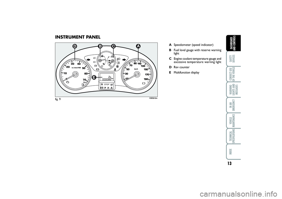
INSTRUMENT PANEL
ASpeedometer (speed indicator)
BFuel level gauge with reserve warning
light
CEngine coolant temperature gauge and
excessive temperature warning light
DRev counter
EMultifunction display
F0P0012m
fig. 9
001-019 SCUDO LUM GB 19/11/13 08.26 Pagina 13
Page 20 of 227
16SAFETY
DEVICESCORRECT USE
OF THE VEHICLE
WARNING
LIGHTS AND
MESSAGESIN AN
EMERGENCYVEHICLE
MAINTENANCETECHNICAL
SPECIFICATIONSINDEXDASHBOARD
AND CONTROLS
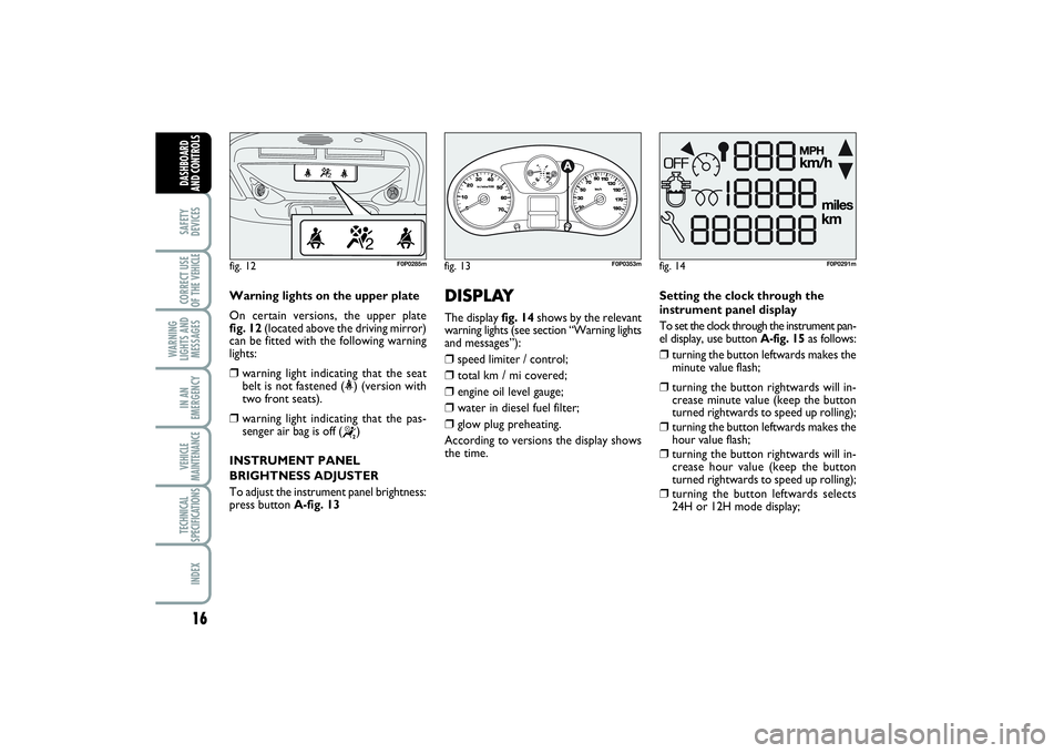
Warning lights on the upper plate
On certain versions, the upper plate
fig. 12(located above the driving mirror)
can be fitted with the following warning
lights:❒
warning light indicating that the seat
belt is not fastened (<) (version with
two front seats).
❒
warning light indicating that the pas-
senger air bag is off (
“
)
INSTRUMENT PANEL
BRIGHTNESS ADJUSTER
To adjust the instrument panel brightness:
press button A-fig. 13
fig. 12
F0P0285m
DISPLAY The display fig. 14shows by the relevant
warning lights (see section “Warning lights
and messages”):❒
speed limiter / control;
❒
total km / mi covered;
❒
engine oil level gauge;
❒
water in diesel fuel filter;
❒
glow plug preheating.
According to versions the display shows
the time. Setting the clock through the
instrument panel display
To set the clock through the instrument pan-
el display, use button A-fig. 15as follows:
❒
turning the button leftwards makes the
minute value flash;
❒
turning the button rightwards will in-
crease minute value (keep the button
turned rightwards to speed up rolling);
❒
turning the button leftwards makes the
hour value flash;
❒
turning the button rightwards will in-
crease hour value (keep the button
turned rightwards to speed up rolling);
❒
turning the button leftwards selects
24H or 12H mode display;
fig. 14
F0P0291m
fig. 13
1/2
F0P0353m
001-019 SCUDO LUM GB 19/11/13 08.26 Pagina 16
Page 21 of 227
17
SAFETY
DEVICESCORRECT USE
OF THE VEHICLE WARNING
LIGHTS AND
MESSAGESIN AN
EMERGENCYVEHICLE
MAINTENANCETECHNICAL
SPECIFICATIONSINDEX DASHBOARD
AND CONTROLS
❒
turn the button rightwards to select the
required mode;
❒
turn the button leftwards to stop clock
setting.
If no other setting is made, after about 30
seconds the display will show the time ac-
cording to the selected settings.
Setting the clock through the
display on the central console
Certain versions are fitted with a central
console with a display showing the time.
To set the clock consult the trip comput-
er under option “Set clock and date”.
GEAR SHIFT
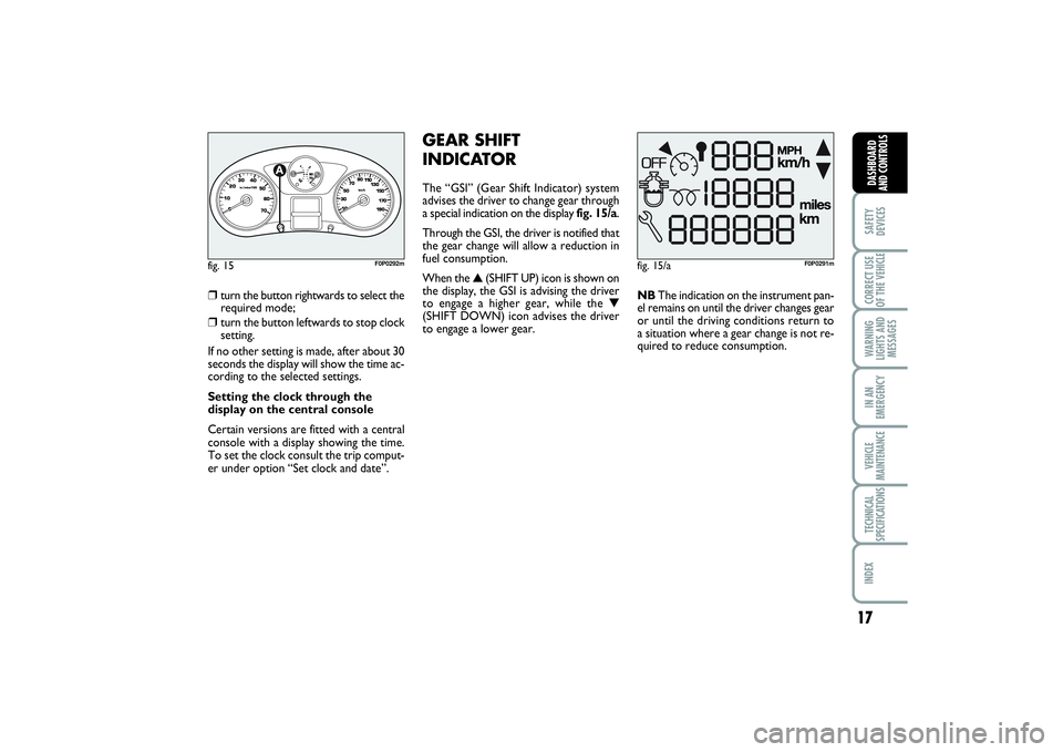
INDICATORThe “GSI” (Gear Shift Indicator) system
advises the driver to change gear through
a special indication on the display fig. 15/a.
Through the GSI, the driver is notified that
the gear change will allow a reduction in
fuel consumption.
When the ▲(SHIFT UP) icon is shown on
the display, the GSI is advising the driver
to engage a higher gear, while the ▼
(SHIFT DOWN) icon advises the driver
to engage a lower gear.NBThe indication on the instrument pan-
el remains on until the driver changes gear
or until the driving conditions return to
a situation where a gear change is not re-
quired to reduce consumption.
fig. 15/a
F0P0291m
fig. 15
1/2
F0P0292m
001-019 SCUDO LUM GB 19/11/13 08.26 Pagina 17
Page 22 of 227
18SAFETY
DEVICESCORRECT USE
OF THE VEHICLE
WARNING
LIGHTS AND
MESSAGESIN AN
EMERGENCYVEHICLE
MAINTENANCETECHNICAL
SPECIFICATIONSINDEXDASHBOARD
AND CONTROLS
MAINTENANCE
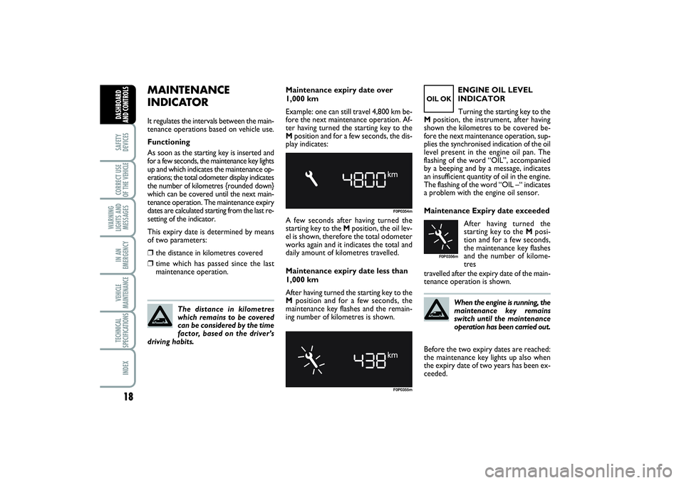
INDICATORIt regulates the intervals between the main-
tenance operations based on vehicle use.
Functioning
As soon as the starting key is inserted and
for a few seconds, the maintenance key lights
up and which indicates the maintenance op-
erations; the total odometer display indicates
the number of kilometres {rounded down}
which can be covered until the next main-
tenance operation. The maintenance expiry
dates are calculated starting from the last re-
setting of the indicator.
This expiry date is determined by means
of two parameters:❒
the distance in kilometres covered
❒
time which has passed since the last
maintenance operation.
The distance in kilometres
which remains to be covered
can be considered by the time
factor, based on the driver’s
driving habits.
F0P0354mF0P0355m
OIL OK
F0P0356m
Maintenance expiry date over
1,000 km
Example: one can still travel 4,800 km be-
fore the next maintenance operation. Af-
ter having turned the starting key to the
Mposition and for a few seconds, the dis-
play indicates:
A few seconds after having turned the
starting key to the Mposition, the oil lev-
el is shown, therefore the total odometer
works again and it indicates the total and
daily amount of kilometres travelled.
Maintenance expiry date less than
1,000 km
After having turned the starting key to the
Mposition and for a few seconds, the
maintenance key flashes and the remain-
ing number of kilometres is shown.ENGINE OIL LEVEL
INDICATOR
Turning the starting key to the
Mposition, the instrument, after having
shown the kilometres to be covered be-
fore the next maintenance operation, sup-
plies the synchronised indication of the oil
level present in the engine oil pan. The
flashing of the word “OIL”, accompanied
by a beeping and by a message, indicates
an insufficient quantity of oil in the engine.
The flashing of the word “OIL –“ indicates
a problem with the engine oil sensor.
Maintenance Expiry date exceeded
After having turned the
starting key to the Mposi-
tion and for a few seconds,
the maintenance key flashes
and the number of kilome-
tres
travelled after the expiry date of the main-
tenance operation is shown.
When the engine is running, the
maintenance key remains
switch until the maintenance
operation has been carried out.
Before the two expiry dates are reached:
the maintenance key lights up also when
the expiry date of two years has been ex-
ceeded.
001-019 SCUDO LUM GB 19/11/13 08.26 Pagina 18
Page 23 of 227
19
SAFETY
DEVICESCORRECT USE
OF THE VEHICLE WARNING
LIGHTS AND
MESSAGESIN AN
EMERGENCYVEHICLE
MAINTENANCETECHNICAL
SPECIFICATIONSINDEX DASHBOARD
AND CONTROLS
Distance to cover
This value shows the distance to be cov-
ered yet, under active navigation condi-
tion.
Trip distance
This value shows the distance covered
from the start of the journey, after reset-
ting (Reset).
Average consumption
This value shows the average consump-
tion from the start of the journey, after
resetting (Reset).
Average speed
This value shows the vehicle average
speed calculated from the start of the
journey, after resetting (Reset).
TRIP COMPUTERThe trip computer enables to display in se-
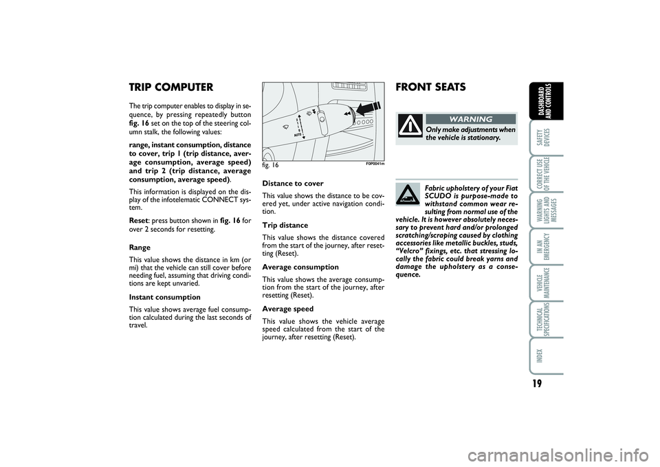
quence, by pressing repeatedly button
fig. 16set on the top of the steering col-
umn stalk, the following values:
range, instant consumption, distance
to cover, trip 1 (trip distance, aver-
age consumption, average speed)
and trip 2 (trip distance, average
consumption, average speed).
This information is displayed on the dis-
play of the infotelematic CONNECT sys-
tem.
Reset: press button shown in fig. 16for
over 2 seconds for resetting.
Range
This value shows the distance in km (or
mi) that the vehicle can still cover before
needing fuel, assuming that driving condi-
tions are kept unvaried.
Instant consumption
This value shows average fuel consump-
tion calculated during the last seconds of
travel.
fig. 16
F0P0041m
FRONT SEATS
Only make adjustments when
the vehicle is stationary.
WARNING
Fabric upholstery of your Fiat
SCUDO is purpose-made to
withstand common wear re-
sulting from normal use of the
vehicle. It is however absolutely neces-
sary to prevent hard and/or prolonged
scratching/scraping caused by clothing
accessories like metallic buckles, studs,
“Velcro” fixings, etc. that stressing lo-
cally the fabric could break yarns and
damage the upholstery as a conse-
quence.
001-019 SCUDO LUM GB 19/11/13 08.26 Pagina 19
Page 43 of 227
39
SAFETY
DEVICESCORRECT USE
OF THE VEHICLE WARNING
LIGHTS AND
MESSAGESIN AN
EMERGENCYVEHICLE
MAINTENANCETECHNICAL
SPECIFICATIONSINDEX DASHBOARD
AND CONTROLS
AUTOMATIC TWO-ZONE CLIMATE CONTROL
SYSTEM (for versions/markets, where provided)
DESCRIPTION
The vehicle is fitted with a two-zone cli-
mate control system which makes it pos-
sible to separately adjust the air temper-
atures and air distribution on the driver’s
side and on the passenger’s side.
Temperature control is based on the
“equivalent temperature” logic, i.e.: the
system continuously works to keep con-
stant the comfort inside the passenger
compartment and to compensate any vari-
ation of the outside climate conditions, in-
cluding sunshine detected by a proper sen-
sor provided for the purpose.
The climate control system automatically
controls and adjusts the following para-
meters and functions:❒
air temperature at driver/front passen-
ger vents;
❒
air distribution at driver/front passen-
ger vents;
❒
fan speed (continuous air flow variation);
❒
compressor activation (to cool/ dehu-
midify air);
❒
air recirculation.All the above functions can be changed
manually by selecting the required func-
tion/s and by changing the set parameters.
In this way the automatic control is de-
activated; the system will resume auto-
matic control only for safety reasons.
Manual selections prevail over automatic
ones and remain in storage until the user
decides to resume automatic control
(press button AUTO, except when the
system cuts in for particular safety condi-
tions. The control of functions not
changed manually remains automatic.
The amount of air admitted to the pas-
senger compartment does not depend on
the vehicle speed, since it is electronical-
ly controlled by the fan. The temperature
of the air admitted to the passenger com-
partment is always controlled automati-
cally according to the temperatures set on
the driver’s and front passenger’s display
(except when the system is off or under
certain conditions when the compressor
is off).The following parameters and functions
can be set or changed manually:
❒
air temperatures on driver/front pas-
senger side;
❒
fan speed (continuous variation);
❒
air distribution on seven levels (dri-
ver/front passenger side);
❒
climate control compressor on/off en-
able;
❒
monozone/two-zone distribution prior-
ity;
❒
fast demisting/defrosting;
❒
air recirculation;
❒
rear heated window;
❒
system deactivation.
020-082 SCUDO LUM GB 19/11/13 09.54 Pagina 39
Page 44 of 227
40SAFETY
DEVICESCORRECT USE
OF THE VEHICLE
WARNING
LIGHTS AND
MESSAGESIN AN
EMERGENCYVEHICLE
MAINTENANCETECHNICAL
SPECIFICATIONSINDEX
DASHBOARD
AND
CONTROLS
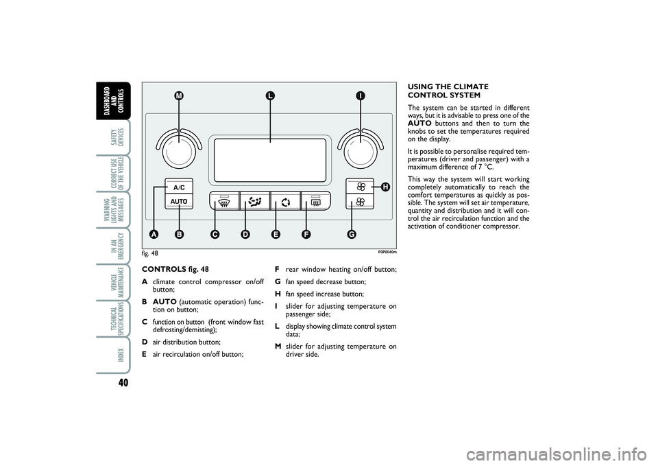
CONTROLS fig. 48
Aclimate control compressor on/off
button;
B AUTO(automatic operation) func-
tion on button;
C
function on button
(front window fast
defrosting/demisting);
Dair distribution button;
Eair recirculation on/off button;USING THE CLIMATE
CONTROL SYSTEM
The system can be started in different
ways, but it is advisable to press one of the
AUTObuttons and then to turn the
knobs to set the temperatures required
on the display.
It is possible to personalise required tem-
peratures (driver and passenger) with a
maximum difference of 7 °C.
This way the system will start working
completely automatically to reach the
comfort temperatures as quickly as pos-
sible. The system will set air temperature,
quantity and distribution and it will con-
trol the air recirculation function and the
activation of conditioner compressor.
fig. 48
F0P0040m
Frear window heating on/off button;
Gfan speed decrease button;
Hfan speed increase button;
Islider for adjusting temperature on
passenger side;
Ldisplay showing climate control system
data;
Mslider for adjusting temperature on
driver side.
020-082 SCUDO LUM GB 19/11/13 09.54 Pagina 40
Page 46 of 227
42SAFETY
DEVICESCORRECT USE
OF THE VEHICLE
WARNING
LIGHTS AND
MESSAGESIN AN
EMERGENCYVEHICLE
MAINTENANCETECHNICAL
SPECIFICATIONSINDEX
DASHBOARD
AND
CONTROLS
¡
Splitting of the air flow between the
vents to the lower part of the pas-
senger compartment (warmest air)
and the dashboard centre and side
outlets (coolest air). This air flow dis-
tribution is particularly useful in
spring and autumn when the sun is
shining.
¬
Splitting of the air flow between
windscreen and front side window
demisting/defrosting vents and the
lower part of the passenger com-
partment. This type of air distribution
allows satisfactory heating of the pas-
senger compartment while prevent-
ing possible misting of the windows.The type of air distribution, when select-
ed by hand, is shown by lighting up of the
relevant led on the selected button.
In the combined function, pressing a but-
ton will activate the relevant function
whereas, pressing a button relevant to an
already operating function will turn off this
function and the relevant button led.
To restore automatic air distribution con-
trol after a manual selection, press button
AUTO.
When the driver selects air distribution to
the windscreen, also the air distribution
on passenger side will be distributed to the
windscreen. The passenger can however
select the required air distribution by
pressing the relevant buttons.Fan speed adjusting buttons G - H
Press button Gpto decrease the fan
speed and therefore the amount of air ad-
mitted into the passenger compartment.
Press button Hpto increase the fan
speed and therefore the amount of air ad-
mitted into the passenger compartment,
although keeping the required tempera-
ture set.
The fan speed is shown by the lit bars of
the fan symbol pon the display:
❒
max fan speed = all bars lit;
❒
min fan speed = one bar lit.
The fan can be cut off only if the climate
control compressor has been switched off
pressing button A.
IMPORTANT To restore automatic fan
speed control after a manual adjustment,
press button AUTO.
020-082 SCUDO LUM GB 19/11/13 09.54 Pagina 42
Page 47 of 227
43
SAFETY
DEVICESCORRECT USE
OF THE VEHICLE WARNING
LIGHTS AND
MESSAGESIN AN
EMERGENCYVEHICLE
MAINTENANCETECHNICAL
SPECIFICATIONSINDEX DASHBOARD
AND CONTROLS
AUTO button
(automatic operation on/off)
Pressing button AUTOthe system auto-
matically adjusts the amount and distribu-
tion of the air admitted to the passenger
compartment, cancelling all the previous
manual adjustments. Manual operation of
at least one automatic function (air recir-
culation, air distribution, fan speed or cli-
mate control compressor off).
IMPORTANT Should the system (after
manual settings) be no longer able to guar-
antee the required temperature set in the
passenger compartment, the set tempera-
ture value will start flashing to indicate this
condition, after one minute the AUTO
message will turn off.To restore system automatic control at
any time, after one or more manual ad-
justments, press button AUTO.
Pressing again button AUTOautomati-
cally aligns the temperature on the pas-
senger side with that on the driver side,
it is therefore possible to set the same
temperature and air distribution between
the two zones by turning the knob on dri-
ver side. This function is provided to sim-
plify temperature adjustment of the whole
passenger compartment when only the
driver is onboard. Separate operation of
set temperature and air distribution is re-
stored by pressing the button AUTO
again.Air recirculation on/off button E
Air recirculation works according to the
following operating logics:
❒
automatic switching on, by pressing one
of the AUTObuttons and indicated by
the turning on of the AUTOicon on the
display.
❒
manual switching on, by pressing but-
ton E, indicated by symbol
Ω
on the
display;
❒
manual switching off, by pressing but-
ton E, indicated by the turning off of
symbol
Ω
on the display.
IMPORTANT The inside air recirculation
system makes it possible to reach the re-
quired heating or cooling conditions faster.
It is however inadvisable to use it on
rainy/cold days as it would considerably
increase the possibility of the windows
misting inside, especially if the climate con-
trol system is off.
020-082 SCUDO LUM GB 19/11/13 09.54 Pagina 43