radio FIAT SPIDER ABARTH 2017 Owner's Manual
[x] Cancel search | Manufacturer: FIAT, Model Year: 2017, Model line: SPIDER ABARTH, Model: FIAT SPIDER ABARTH 2017Pages: 292, PDF Size: 9.24 MB
Page 200 of 292

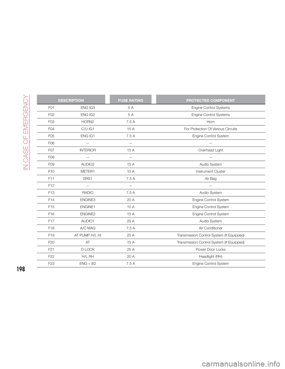
DESCRIPTION FUSE RATING PROTECTED COMPONENT
F01 ENG IG3 5 A Engine Control Systems
F02 ENG
IG2 5 A Engine Control Systems
F03 HORN2 7.5 A Horn
F04 C/U IG1 15 A For Protection Of Various Circuits
F05 ENG IG1 7.5 A Engine Control System
F06 — — —
F07 INTERIOR 15 A Overhead Light
F08 — — —
F09 AUDIO2 15 A Audio System
F10 METER1 10 A Instrument Cluster
F11 SRS1 7.5 A Air Bag
F12 — — —
F13 RADIO 7.5 A Audio System
F14 ENGINE3 20 A Engine Control System
F15 ENGINE1 10 A Engine Control System
F16 ENGINE2 15 A Engine Control System
F17 AUDIO1 25 A Audio System
F18 A/C MAG 7.5 A Air Conditioner
F19 AT PUMP H/L HI 20 A Transmission Control System (If Equipped)
F20 AT 15 A Transmission Control System (If Equipped)
F21 D LOCK 25 A Power Door Locks
F22 H/L RH 20 A Headlight (RH)
F23 ENG + B2 7.5 A Engine Control System
198
IN CASE OF EMERGENCY
Page 288 of 292

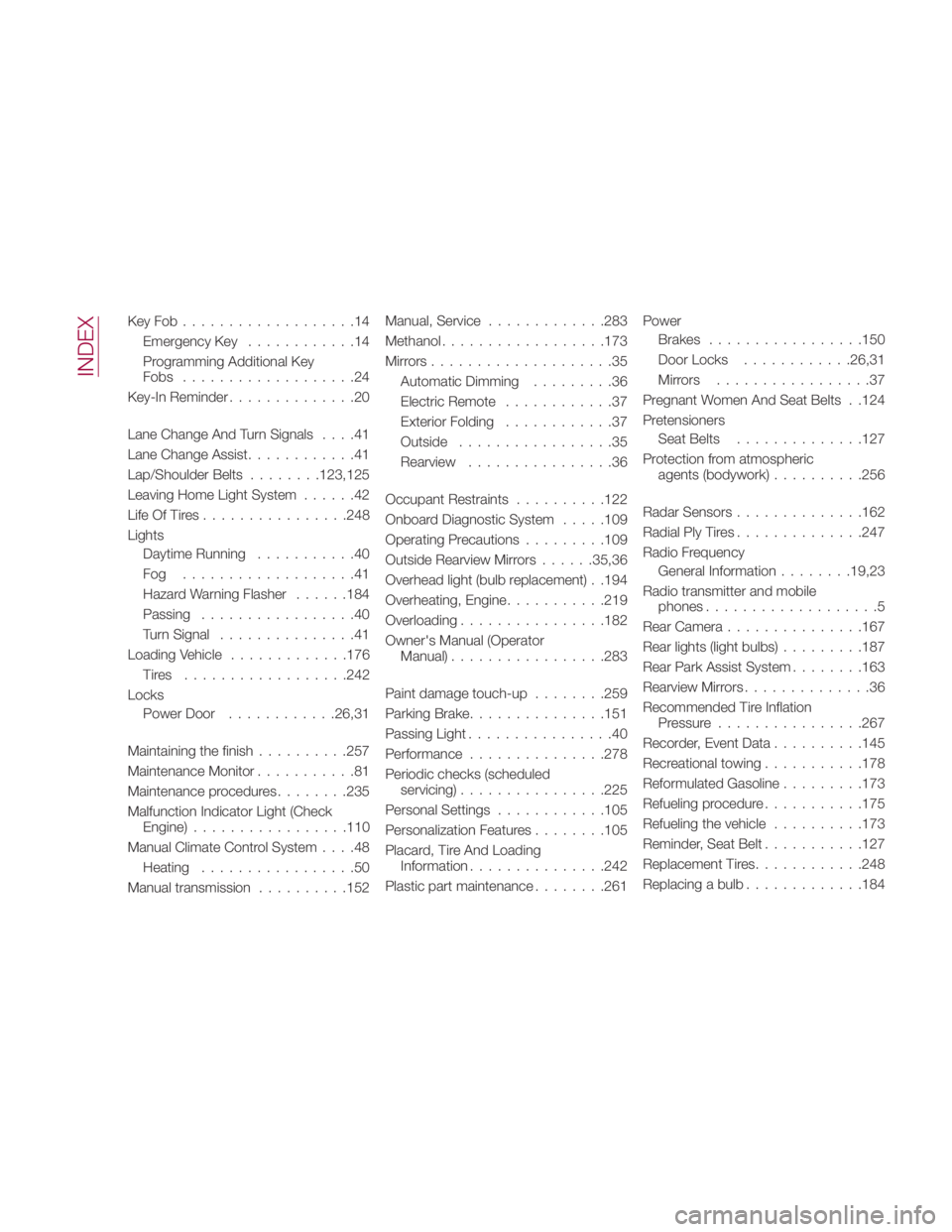
KeyFob...................14
Emergency Key ............14
Programming Additional Key
Fobs ...................24
Key-In Reminder ..............20
Lane Change And Turn Signals ....41
Lane Change Assist ............41
Lap/Shoulder Belts ....... .123,125
Leaving Home Light System ......42
Life Of Tires ............... .248
Lights
Daytime Running ...........40
Fog ...................41
Hazard Warning Flasher ..... .184
Passing .................40
Turn Signal ...............41
Loading Vehicle ............ .176
Tires ................. .242
Locks
PowerDoor ........... .26,31
Maintaining the finish ......... .257
Maintenance Monitor ...........81
Maintenance procedures ....... .235
Malfunction Indicator Light (Check
Engine) ................ .110
Manual Climate Control System ....48
Heating .................50
Manual transmission ......... .152 Manual, Service ............ .283
Methanol ................. .173
Mirrors....................35
Automatic Dimming .........36
Electric Remote ............37
Exterior Folding ............37
Outside .................35
Rearview ................36
Occupant Restraints ......... .122
Onboard Diagnostic System .... .109
Operating Precautions ........ .109
Outside Rearview Mirrors ..... .35,36
Overhead light (bulb replacement) . .194
Overheating, Engine .......... .219
Overloading ............... .182
Owner's Manual (Operator
Manual) ................ .283
Paint damage touch-up ....... .259
Parking Brake ..............
.151
Passing
Light ................ 40
Performance .............. .278
Periodic checks (scheduled
servicing) ............... .225
Personal Settings ........... .105
Personalization Features ....... .105
Placard, Tire And Loading
Information .............. .242
Plastic part maintenance ....... .261 Power
Brakes ................ .150
Door Locks ........... .26,31
Mirrors .................37
Pregnant Women And Seat Belts . .124
Pretensioners
Seat Belts ............. .127
Protection from atmospheric
agents (bodywork) ......... .256
Radar Sensors ............. .162
Radial Ply Tires ............. .247
Radio Frequency
General Information ....... .19,23
Radio transmitter and mobile
phones ...................5
Rear Camera .............. .167
Rear lights (light bulbs) ........ .187
Rear Park Assist System ....... .163
Rearview Mirrors ..............36
Recommended Tire Inflation
Pressure ............... .267
Recorder, Event Data ......... .145
Recreational towing .......... .178
Reformulated Gasoline ........ .173
Refueling procedure .......... .175
Refueling the vehicle ......... .173
Reminder, Seat Belt .......... .127
Replacement Tires ........... .248
Replacing a bulb ............ .184
INDEX
Page 291 of 292

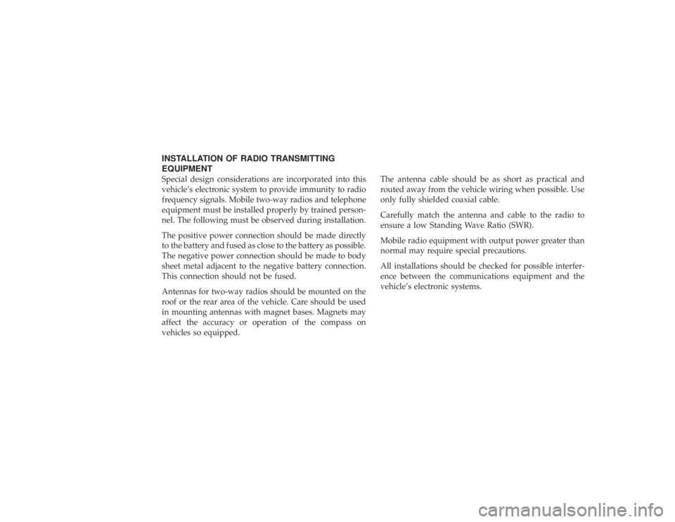
INSTALLATION OF RADIO TRANSMITTING
EQUIPMENT
Special design considerations are incorporated into this
vehicle’s electronic system to provide immunity to radio
frequency signals. Mobile two-way radios and telephone
equipment must be installed properly by trained person-
nel. The following must be observed during installation.
The positive power connection should be made directly
to the battery and fused as close to the battery as possible.
The negative power connection should be made to body
sheet metal adjacent to the negative battery connection.
This connection should not be fused.
Antennas for two-way radios should be mounted on the
roof or the rear area of the vehicle. Care should be used
in mounting antennas with magnet bases. Magnets may
affect the accuracy or operation of the compass on
vehicles so equipped.
The antenna cable should be as short as practical and
routed away from the vehicle wiring when possible. Use
only fully shielded coaxial cable.
Carefully match the antenna and cable to the radio to
ensure a low Standing Wave Ratio (SWR).
Mobile radio equipment with output power greater than
normal may require special precautions.
All installations should be checked for possible interfer-
ence between the communications equipment and the
vehicle’s electronic systems.