boot FIAT STILO 2006 1.G Owner's Manual
[x] Cancel search | Manufacturer: FIAT, Model Year: 2006, Model line: STILO, Model: FIAT STILO 2006 1.GPages: 274, PDF Size: 4.76 MB
Page 164 of 274
163
IN AN
EMERGENCY
CAR
MAINTENANCE
TECHNICAL
SPECIFICATIONS
INDEX
DASHBOARD
AND CONTROLS
SAFETY
DEVICES
CORRECT USE
OF THE CAR
WARNING
LIGHTS AND
MESSAGES
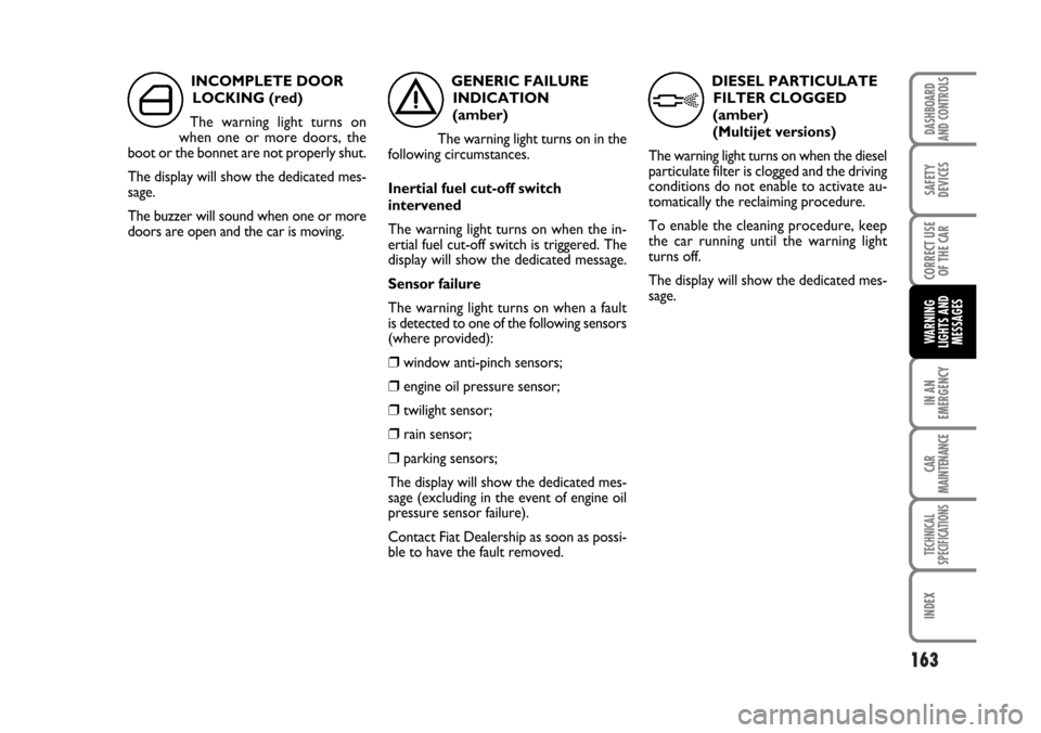
INCOMPLETE DOOR
LOCKING (red)
The warning light turns on
when one or more doors, the
boot or the bonnet are not properly shut.
The display will show the dedicated mes-
sage.
The buzzer will sound when one or more
doors are open and the car is moving.GENERIC FAILURE
INDICATION
(amber)
The warning light turns on in the
following circumstances.
Inertial fuel cut-off switch
intervened
The warning light turns on when the in-
ertial fuel cut-off switch is triggered. The
display will show the dedicated message.
Sensor failure
The warning light turns on when a fault
is detected to one of the following sensors
(where provided):
❒window anti-pinch sensors;
❒engine oil pressure sensor;
❒twilight sensor;
❒rain sensor;
❒parking sensors;
The display will show the dedicated mes-
sage (excluding in the event of engine oil
pressure sensor failure).
Contact Fiat Dealership as soon as possi-
ble to have the fault removed.
´è
DIESEL PARTICULATE
FILTER CLOGGED
(amber)
(Multijet versions)
The warning light turns on when the diesel
particulate filter is clogged and the driving
conditions do not enable to activate au-
tomatically the reclaiming procedure.
To enable the cleaning procedure, keep
the car running until the warning light
turns off.
The display will show the dedicated mes-
sage.
h
Page 177 of 274
176
WARNING
LIGHTS AND
MESSAGES
CAR
MAINTENANCE
TECHNICAL
SPECIFICATIONS
IINDEX
DASHBOARD
AND CONTROLS
SAFETY
DEVICES
CORRECT USE
OF THE CAR
IN AN
EMERGENCY
Versions with alloy rims
Proceed as follows:
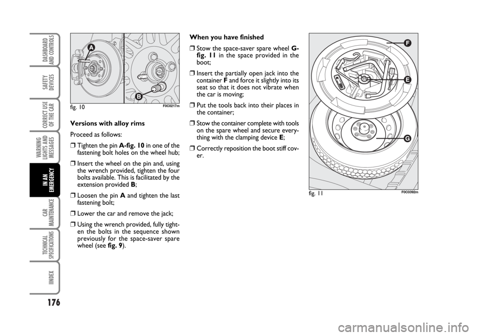
❒Tighten the pin A-fig. 10in one of the
fastening bolt holes on the wheel hub;
❒Insert the wheel on the pin and, using
the wrench provided, tighten the four
bolts available. This is facilitated by the
extension provided B;
❒Loosen the pin Aand tighten the last
fastening bolt;
❒Lower the car and remove the jack;
❒Using the wrench provided, fully tight-
en the bolts in the sequence shown
previously for the space-saver spare
wheel (see fig. 9).When you have finished
❒Stow the space-saver spare wheel G-
fig. 11in the space provided in the
boot;
❒Insert the partially open jack into the
container Fand force it slightly into its
seat so that it does not vibrate when
the car is moving;
❒ Put the tools back into their places in
the container;
❒Stow the container complete with tools
on the spare wheel and secure every-
thing with the clamping device E;
❒Correctly reposition the boot stiff cov-
er.
fig. 10F0C0217m
fig. 11F0C0392m
Page 178 of 274
177
WARNING
LIGHTS AND
MESSAGES
CAR
MAINTENANCE
TECHNICAL
SPECIFICATIONS
INDEX
DASHBOARD
AND CONTROLS
SAFETY
DEVICES
CORRECT USE
OF THE CAR
IN AN
EMERGENCY
QUICK TYRE REPAIR
KIT FIX & GO
automatic
The quick tyre repair kit Fix & Go auto-
matic is located in the appropriate con-
tainer in the boot .
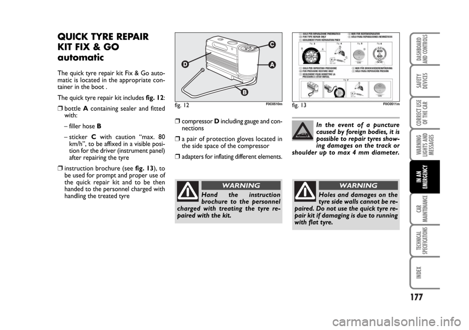
The quick tyre repair kit includes fig. 12:
❒bottle A containing sealer and fitted
with:
– filler hose B
– sticker Cwith caution “max. 80
km/h”, to be affixed in a visible posi-
tion for the driver (instrument panel)
after repairing the tyre
❒instruction brochure (see fig. 13), to
be used for prompt and proper use of
the quick repair kit and to be then
handed to the personnel charged with
handling the treated tyre
fig. 12F0C0510mfig. 13F0C0511m
Hand the instruction
brochure to the personnel
charged with treating the tyre re-
paired with the kit.
WARNING
In the event of a puncture
caused by foreign bodies, it is
possible to repair tyres show-
ing damages on the track or
shoulder up to max 4 mm diameter.
Holes and damages on the
tyre side walls cannot be re-
paired. Do not use the quick tyre re-
pair kit if damaging is due to running
with flat tyre.
WARNING
❒compressor Dincluding gauge and con-
nections
❒a pair of protection gloves located in
the side space of the compressor
❒adapters for inflating different elements.
Page 184 of 274
183
WARNING
LIGHTS AND
MESSAGES
CAR
MAINTENANCE
TECHNICAL
SPECIFICATIONS
INDEX
DASHBOARD
AND CONTROLS
SAFETY
DEVICES
CORRECT USE
OF THE CAR
IN AN
EMERGENCY
E
D
D
F
A
E
B
A
B
B
B
B
B
B
B
A
B
B
A
C
A
C
C
C
A
CH1
H7
H7
D2R
W5W
H1
PY21W
WY5W
P21W
W5W
P4/21W
P21/5W
P21W
R5W
P21W
W2,3W
P21W
P21W
W5W
C5W
W5W
C5W
C10W
C5W
W5W
C5W55W
55W
55W
35W
5W
55W
21W
5W
21W
5W
4W/21W
21W/5W
21W
5W
21W
2,3W
21W
21W
5W
5W
5W
5W
10W
5W
5W
5W
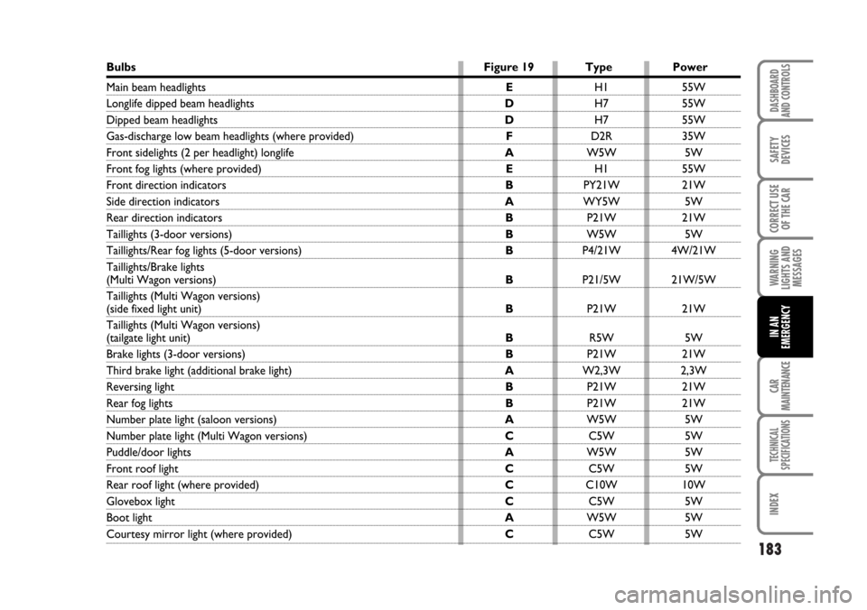
Bulbs Figure 19 Type Power
Main beam headlights
Longlife dipped beam headlights
Dipped beam headlights
Gas-discharge low beam headlights (where provided)
Front sidelights (2 per headlight) longlife
Front fog lights (where provided)
Front direction indicators
Side direction indicators
Rear direction indicators
Taillights (3-door versions)
Taillights/Rear fog lights (5-door versions)
Taillights/Brake lights
(Multi Wagon versions)
Taillights (Multi Wagon versions)
(side fixed light unit)
Taillights (Multi Wagon versions)
(tailgate light unit)
Brake lights (3-door versions)
Third brake light (additional brake light)
Reversing light
Rear fog lights
Number plate light (saloon versions)
Number plate light (Multi Wagon versions)
Puddle/door lights
Front roof light
Rear roof light (where provided)
Glovebox light
Boot light
Courtesy mirror light (where provided)
Page 188 of 274
187
WARNING
LIGHTS AND
MESSAGES
CAR
MAINTENANCE
TECHNICAL
SPECIFICATIONS
INDEX
DASHBOARD
AND CONTROLS
SAFETY
DEVICES
CORRECT USE
OF THE CAR
IN AN
EMERGENCY
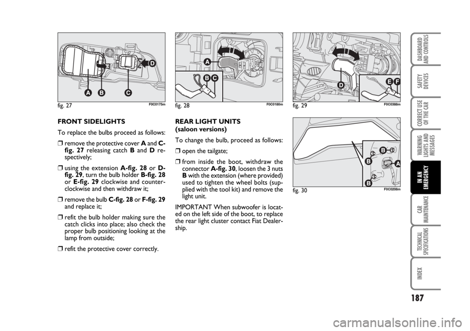
FRONT SIDELIGHTS
To replace the bulbs proceed as follows:
❒remove the protective cover Aand C-
fig. 27releasing catch Band Dre-
spectively;
❒using the extension A-fig. 28or D-
fig. 29, turn the bulb holder B-fig. 28
or E-fig. 29clockwise and counter-
clockwise and then withdraw it;
❒remove the bulb C-fig. 28or F-fig. 29
and replace it;
❒refit the bulb holder making sure the
catch clicks into place; also check the
proper bulb positioning looking at the
lamp from outside;
❒refit the protective cover correctly.REAR LIGHT UNITS
(saloon versions)
To change the bulb, proceed as follows:
❒open the tailgate;
❒from inside the boot, withdraw the
connector A-fig. 30, loosen the 3 nuts
Bwith the extension (where provided)
used to tighten the wheel bolts (sup-
plied with the tool kit) and remove the
light unit.
IMPORTANT When subwoofer is locat-
ed on the left side of the boot, to replace
the rear light cluster contact Fiat Dealer-
ship.
fig. 27F0C0175mfig. 28F0C0180mfig. 29F0C0388m
fig. 30F0C0208m
Page 196 of 274
195
WARNING
LIGHTS AND
MESSAGES
CAR
MAINTENANCE
TECHNICAL
SPECIFICATIONS
INDEX
DASHBOARD
AND CONTROLS
SAFETY
DEVICES
CORRECT USE
OF THE CAR
IN AN
EMERGENCY
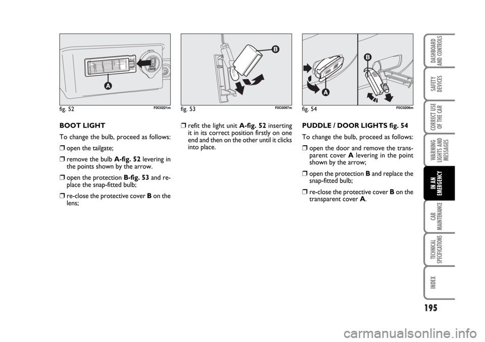
BOOT LIGHT
To change the bulb, proceed as follows:
❒open the tailgate;
❒remove the bulb A-fig. 52levering in
the points shown by the arrow.
❒open the protection B-fig. 53and re-
place the snap-fitted bulb;
❒re-close the protective cover Bon the
lens;
fig. 52F0C0221mfig. 53F0C0097mfig. 54F0C0206m
❒refit the light unit A-fig. 52inserting
it in its correct position firstly on one
end and then on the other until it clicks
into place.PUDDLE / DOOR LIGHTS fig. 54
To change the bulb, proceed as follows:
❒ open the door and remove the trans-
parent cover Alevering in the point
shown by the arrow;
❒open the protection Band replace the
snap-fitted bulb;
❒ re-close the protective cover Bon the
transparent cover A.
Page 198 of 274
197
WARNING
LIGHTS AND
MESSAGES
CAR
MAINTENANCE
TECHNICAL
SPECIFICATIONS
INDEX
DASHBOARD
AND CONTROLS
SAFETY
DEVICES
CORRECT USE
OF THE CAR
IN AN
EMERGENCY
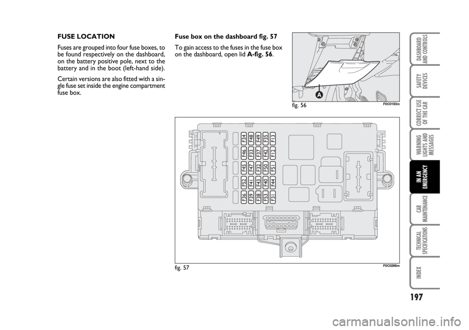
FUSE LOCATION
Fuses are grouped into four fuse boxes, to
be found respectively on the dashboard,
on the battery positive pole, next to the
battery and in the boot (left-hand side).
Certain versions are also fitted with a sin-
gle fuse set inside the engine compartment
fuse box.
fig. 57F0C0266m
fig. 56F0C0193m
Fuse box on the dashboard fig. 57
To gain access to the fuses in the fuse box
on the dashboard, open lid A-fig. 56.
Page 201 of 274
200
WARNING
LIGHTS AND
MESSAGES
CAR
MAINTENANCE
TECHNICAL
SPECIFICATIONS
IINDEX
DASHBOARD
AND CONTROLS
SAFETY
DEVICES
CORRECT USE
OF THE CAR
IN AN
EMERGENCY
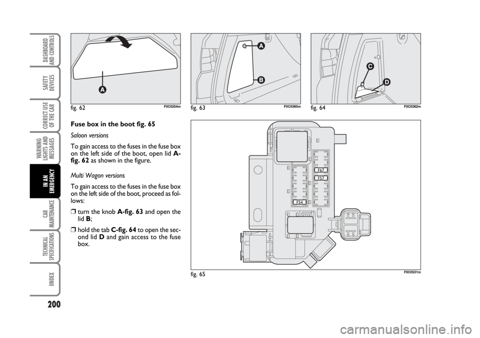
Fuse box in the boot fig. 65
Saloon versions
To gain access to the fuses in the fuse box
on the left side of the boot, open lid A-
fig. 62as shown in the figure.
Multi Wagon versions
To gain access to the fuses in the fuse box
on the left side of the boot, proceed as fol-
lows:
❒turn the knob A-fig. 63and open the
lid B;
❒hold the tab C-fig. 64to open the sec-
ond lid Dand gain access to the fuse
box.
fig. 62F0C0254mfig. 63F0C0360mfig. 64F0C0362m
fig. 65F0C0531m
Page 203 of 274
202
WARNING
LIGHTS AND
MESSAGES
CAR
MAINTENANCE
TECHNICAL
SPECIFICATIONS
IINDEX
DASHBOARD
AND CONTROLS
SAFETY
DEVICES
CORRECT USE
OF THE CAR
IN AN
EMERGENCY
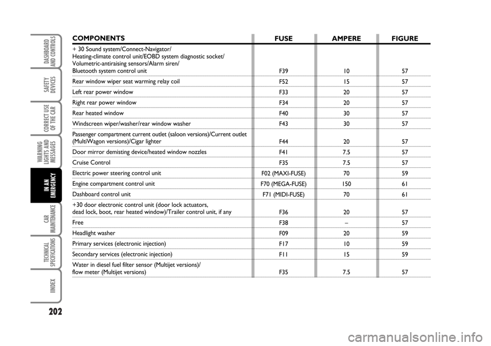
COMPONENTS
+ 30 Sound system/Connect-Navigator/
Heating-climate control unit/EOBD system diagnostic socket/
Volumetric-antiraising sensors/Alarm siren/
Bluetooth system control unit
Rear window wiper seat warming relay coil
Left rear power window
Right rear power window
Rear heated window
Windscreen wiper/washer/rear window washer
Passenger compartment current outlet (saloon versions)/Current outlet
(MultiWagon versions)/Cigar lighter
Door mirror demisting device/heated window nozzles
Cruise Control
Electric power steering control unit
Engine compartment control unit
Dashboard control unit
+30 door electronic control unit (door lock actuators,
dead lock, boot, rear heated window)/Trailer control unit, if any
Free
Headlight washer
Primary services (electronic injection)
Secondary services (electronic injection)
Water in diesel fuel filter sensor (Multijet versions)/
flow meter (Multijet versions)
FUSE
F39
F52
F33
F34
F40
F43
F44
F41
F35
F02 (MAXI-FUSE)
F70 (MEGA-FUSE)
F71 (MIDI-FUSE)
F36
F38
F09
F17
F11
F35
AMPERE
10
15
20
20
30
30
20
7.5
7.5
70
150
70
20
–
20
10
15
7.5
FIGURE
57
57
57
57
57
57
57
57
57
59
61
61
57
57
59
59
59
57
Page 207 of 274
TOWING THE CAR
The tow ring provided with the car is
housed in the tool box under the boot
mat.
TOW RING HOOKING
Proceed as follows:
❒release the cap operating the tab A-
fig. 67-68;
❒take the tow hook Bfrom its support;
❒ tighten the ring on the rear or front
threaded pin.
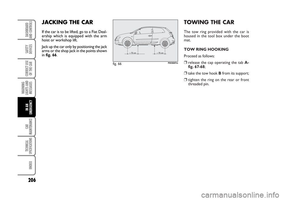
fig. 66F0C0247m
206
WARNING
LIGHTS AND
MESSAGES
CAR
MAINTENANCE
TECHNICAL
SPECIFICATIONS
IINDEX
DASHBOARD
AND CONTROLS
SAFETY
DEVICES
CORRECT USE
OF THE CAR
IN AN
EMERGENCY
JACKING THE CAR
If the car is to be lifted, go to a Fiat Deal-
ership which is equipped with the arm
hoist or workshop lift.
Jack up the car only by positioning the jack
arms or the shop jack in the points shown
in fig. 66.