boot FIAT STILO 2006 1.G User Guide
[x] Cancel search | Manufacturer: FIAT, Model Year: 2006, Model line: STILO, Model: FIAT STILO 2006 1.GPages: 274, PDF Size: 4.76 MB
Page 88 of 274
87
SAFETY
DEVICES
CORRECT USE
OF THE CAR
WARNING
LIGHTS AND
MESSAGES
IN AN
EMERGENCY
CAR
MAINTENANCE
TECHNICAL
SPECIFICATIONS
INDEX
DASHBOARD
AND CONTROLS
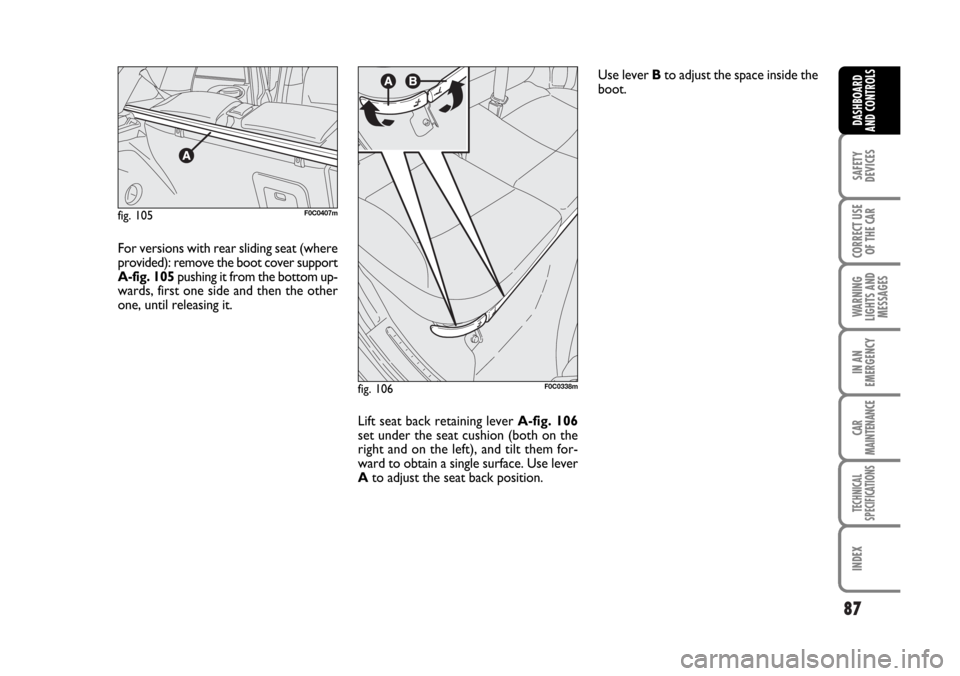
For versions with rear sliding seat (where
provided): remove the boot cover support
A-fig. 105pushing it from the bottom up-
wards, first one side and then the other
one, until releasing it.
Lift seat back retaining lever A-fig. 106
set under the seat cushion (both on the
right and on the left), and tilt them for-
ward to obtain a single surface. Use lever
Ato adjust the seat back position. Use lever Bto adjust the space inside the
boot.
fig. 105F0C0407m
fig. 106F0C0338m
Page 89 of 274
88
SAFETY
DEVICES
CORRECT USE
OF THE CAR
WARNING
LIGHTS AND
MESSAGES
IN AN
EMERGENCY
CAR
MAINTENANCE
TECHNICAL
SPECIFICATIONS
INDEX
DASHBOARD
AND CONTROLS
fig. 110F0C0354m
BOOT COVER
(Multi Wagon versions)
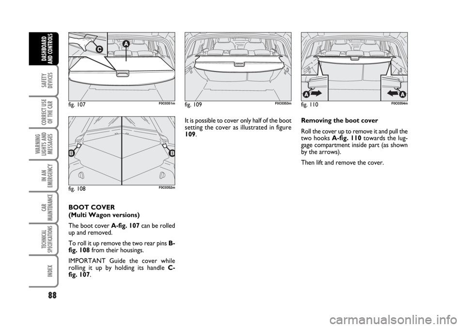
The boot cover A-fig. 107can be rolled
up and removed.
To roll it up remove the two rear pins B-
fig. 108from their housings.
IMPORTANT Guide the cover while
rolling it up by holding its handle C-
fig. 107. It is possible to cover only half of the boot
setting the cover as illustrated in figure
109.
fig. 109F0C0353m
fig. 108F0C0352m
fig. 107F0C0351m
Removing the boot cover
Roll the cover up to remove it and pull the
two hooks A-fig. 110towards the lug-
gage compartment inside part (as shown
by the arrows).
Then lift and remove the cover.
Page 91 of 274
90
SAFETY
DEVICES
CORRECT USE
OF THE CAR
WARNING
LIGHTS AND
MESSAGES
IN AN
EMERGENCY
CAR
MAINTENANCE
TECHNICAL
SPECIFICATIONS
INDEX
DASHBOARD
AND CONTROLS
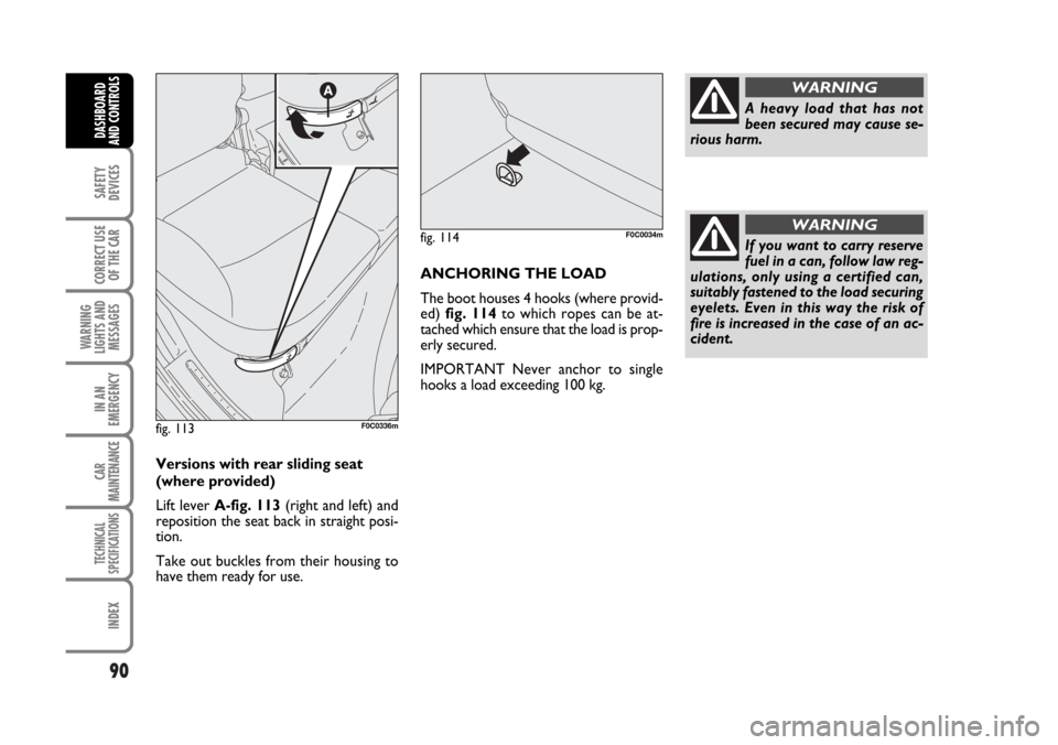
Versions with rear sliding seat
(where provided)
Lift lever A-fig. 113(right and left) and
reposition the seat back in straight posi-
tion.
Take out buckles from their housing to
have them ready for use.ANCHORING THE LOAD
The boot houses 4 hooks (where provid-
ed) fig. 114to which ropes can be at-
tached which ensure that the load is prop-
erly secured.
IMPORTANT Never anchor to single
hooks a load exceeding 100 kg.
fig. 113F0C0336m
fig. 114F0C0034m
A heavy load that has not
been secured may cause se-
rious harm.
WARNING
If you want to carry reserve
fuel in a can, follow law reg-
ulations, only using a certified can,
suitably fastened to the load securing
eyelets. Even in this way the risk of
fire is increased in the case of an ac-
cident.
WARNING
Page 92 of 274
91
SAFETY
DEVICES
CORRECT USE
OF THE CAR
WARNING
LIGHTS AND
MESSAGES
IN AN
EMERGENCY
CAR
MAINTENANCE
TECHNICAL
SPECIFICATIONS
INDEX
DASHBOARD
AND CONTROLS
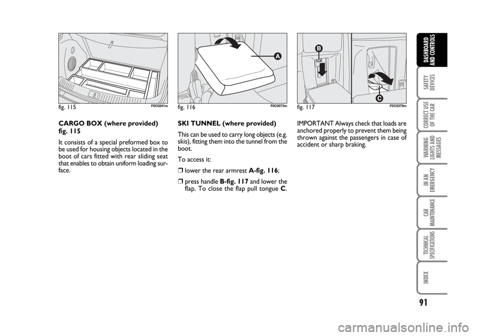
SKI TUNNEL (where provided)
This can be used to carry long objects (e.g.
skis), fitting them into the tunnel from the
boot.
To access it:
❒lower the rear armrest A-fig. 116;
❒press handle B-fig. 117and lower the
flap. To close the flap pull tongue C.IMPORTANT Always check that loads are
anchored properly to prevent them being
thrown against the passengers in case of
accident or sharp braking.
fig. 116F0C0073mfig. 117F0C0379mfig. 115F0C0241m
CARGO BOX (where provided)
fig. 115
It consists of a special preformed box to
be used for housing objects located in the
boot of cars fitted with rear sliding seat
that enables to obtain uniform loading sur-
face.
Page 95 of 274
94
SAFETY
DEVICES
CORRECT USE
OF THE CAR
WARNING
LIGHTS AND
MESSAGES
IN AN
EMERGENCY
CAR
MAINTENANCE
TECHNICAL
SPECIFICATIONS
INDEX
DASHBOARD
AND CONTROLS
HEADLIGHTS
ADJUSTING THE HEADLIGHT
BEAM
Proper adjustment of the headlight beams
is of vital importance for your safety and
comfort and also for the other road users.
To ensure you and other drivers have the
best visibility conditions when travelling
with the headlights on, the headlights must
be set properly. Contact Fiat Dealership
to have the headlights properly adjusted.
IMPORTANT When turning on gas dis-
charge headlight lamps (where provided),
it is normal that there should be a vertical
movement of lenses, and consequently the
same will also happen to the light beam,
for the time required to achieve the cor-
rect headlight trim stabilisation, equal to
approx. 2 seconds.HEADLIGHT AIMING DEVICE
This device can be operated with the ig-
nition key at MARand dipped beams on.
When the car is loaded, it slopes back-
wards. This means that the headlight beam
rises. In this case, it is necessary to return
it to the correct position.
To adjust the headlight slant
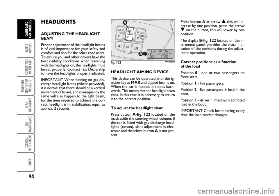
Press button A-fig. 122located on the
mask aside the steering wheel column; if
the car is fitted with gas discharge head-
lights (xenon), slant adjustment is elec-
tronic and therefore button Ais not pre-
sent.Press button Aat arrow
Nthis will in-
crease by one position, press the arrow
Oon the button, this will lower by one
position.
The display B-fig. 122located on the in-
strument panel, provides the visual indi-
cation of the positions during the adjust-
ment operation.
Correct positions as a function
of the load
Position 0- one or two passengers on
front seats.
Position 1- five passengers.
Position 2- five passengers + load in the
boot.
Position 3- driver + maximum admitted
load in the boot.
IMPORTANT Check beam aiming every
time the load carried changes.
fig. 122F0C0533m
Page 108 of 274
107
SAFETY
DEVICES
CORRECT USE
OF THE CAR
WARNING
LIGHTS AND
MESSAGES
IN AN
EMERGENCY
CAR
MAINTENANCE
TECHNICAL
SPECIFICATIONS
INDEX
DASHBOARD
AND CONTROLS
FUEL LID EMERGENCY
OPENINGS
Saloon versions
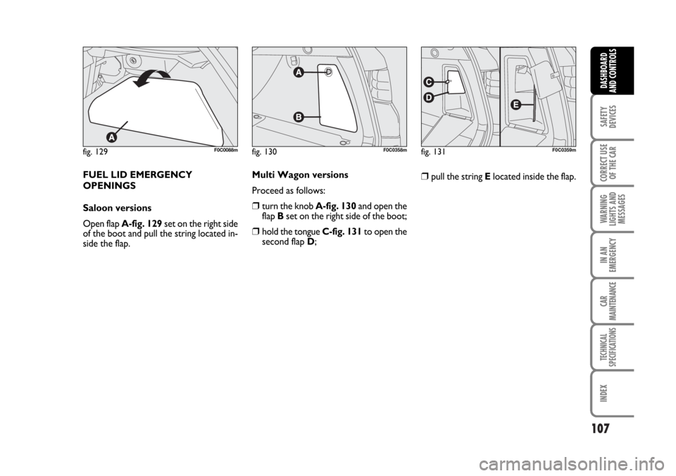
Open flap A-fig. 129set on the right side
of the boot and pull the string located in-
side the flap.
fig. 129F0C0088mfig. 130F0C0358mfig. 131F0C0359m
❒pull the string Elocated inside the flap. Multi Wagon versions
Proceed as follows:
❒turn the knob A-fig. 130and open the
flap Bset on the right side of the boot;
❒hold the tongue C-fig. 131to open the
second flap D;
Page 124 of 274
123
CORRECT USE
OF THE CAR
WARNING
LIGHTS AND
MESSAGES
IN AN
EMERGENCY
CAR
MAINTENANCE
TECHNICAL
SPECIFICATIONS
INDEX
DASHBOARD
AND CONTROLS
SAFETY
DEVICES
Group 1
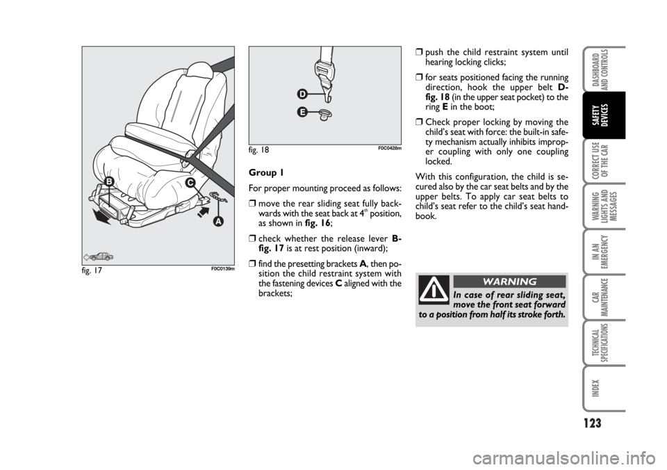
For proper mounting proceed as follows:
❒move the rear sliding seat fully back-
wards with the seat back at 4thposition,
as shown in fig. 16;
❒check whether the release lever B-
fig. 17is at rest position (inward);
❒find the presetting brackets A, then po-
sition the child restraint system with
the fastening devices Caligned with the
brackets;
❒push the child restraint system until
hearing locking clicks;
❒for seats positioned facing the running
direction, hook the upper belt D-
fig. 18(in the upper seat pocket) to the
ring E in the boot;
❒Check proper locking by moving the
child’s seat with force: the built-in safe-
ty mechanism actually inhibits improp-
er coupling with only one coupling
locked.
With this configuration, the child is se-
cured also by the car seat belts and by the
upper belts. To apply car seat belts to
child’s seat refer to the child’s seat hand-
book.
fig. 17F0C0139m
fig. 18F0C0428m
In case of rear sliding seat,
move the front seat forward
to a position from half its stroke forth.
WARNING
Page 125 of 274
124
CORRECT USE
OF THE CAR
WARNING
LIGHTS AND
MESSAGES
IN AN
EMERGENCY
CAR
MAINTENANCE
TECHNICAL
SPECIFICATIONS
IINDEX
DASHBOARD
AND CONTROLS
SAFETY
DEVICES
PRESETTING FOR
MOUNTING THE
“UNIVERSAL ISOFIX”
CHILD RESTRAINT
SYSTEM
This car is preset for mounting the “Uni-
versal Isofix” child restraint system, a new
European standardised system for carry-
ing children safely.
The “Universal Isofix” child’s seat covers
weight group: 1.
Due to its different anchoring system, the
Universal Isofix child’s seat shall be an-
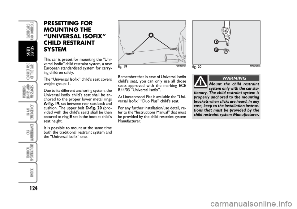
chored to the proper lower metal rings
A-fig. 19, set between rear seat back and
cushion. The upper belt D-fig. 20(pro-
vided with the child’s seat) shall be then
secured to ring Eset in the boot at child’s
seat height.
It is possible to mount at the same time
both the traditional restraint system and
the “Universal Isofix” one.Remember that in case of Universal Isofix
child’s seat, you can only use all those
seats approved with the marking ECE
R44/03 “Universal Isofix”.
At Lineaccessori Fiat is available the “Uni-
versal Isofix” “Duo Plus” child’s seat.
For any further installation/use detail, re-
fer to the “Instructions Manual” that must
be provided by the child restraint system
Manufacturer.
fig. 19F0C0274mfig. 20F0C0428m
Mount the child restraint
system only with the car sta-
tionary. The child restraint system is
properly anchored to the mounting
brackets when clicks are heard. In any
case, keep to the installation instruc-
tions that must be provided by the
child restraint system Manufacturer.
WARNING
Page 133 of 274
132
CORRECT USE
OF THE CAR
WARNING
LIGHTS AND
MESSAGES
IN AN
EMERGENCY
CAR
MAINTENANCE
TECHNICAL
SPECIFICATIONS
IINDEX
DASHBOARD
AND CONTROLS
SAFETY
DEVICES
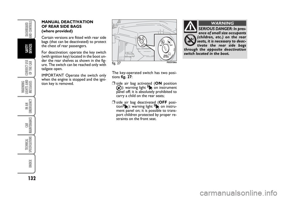
The key-operated switch has two posi-
tions fig. 27:
❒side air bag activated (ONposition
Õ): warning light Àon instrument
panel off; it is absolutely prohibited to
carry a child on the rear seats;
❒side air bag deactivated (OFFposi-
tion
À): warning light Àon instru-
ment panel on; it is possible to trans-
port children protected by proper re-
straints on the front seat.
fig. 27F0C0154m
SERIOUS DANGER: In pres-
ence of small size occupants
(children, etc.) on the rear
seats, it is necessary to deac-
tivate the rear side bags
through the apposite deactivation
switch located in the boot.
WARNINGMANUAL DEACTIVATION
OF REAR SIDE BAGS
(where provided)
Certain versions are fitted with rear side
bags (that can be deactivated) to protect
the chest of rear passengers.
For deactivation: operate the key switch
(with ignition key) located in the boot un-
der the rear shelves as shown in the fig-
ure. The switch can be reached only with
tailgate open.
IMPORTANT Operate the switch only
when the engine is stopped and the igni-
tion key is removed.
Page 150 of 274
149
WARNING
LIGHTS AND
MESSAGES
IN AN
EMERGENCY
CAR
MAINTENANCE
TECHNICAL
SPECIFICATIONS
INDEX
DASHBOARD
AND CONTROLS
SAFETY
DEVICES
CORRECT USE
OF THE CAR
CONTAINING
RUNNING COSTS
Here are some suggestions which may
help you to keep the running costs of your
car down and lower the amount of toxic
emissions released into the atmosphere.
GENERAL CONSIDERATIONS
Car maintenance
Have checks and adjustments carried out
in accordance with the “Service schedule”.
Tyres
Check the pressure of the tyres routine-
ly at an interval of no more than 4 weeks:
if the pressure is too low, consumption
levels increase as resistance to rolling is
higher.
Unnecessary loads
Do not travel with too much luggage
stowed in the boot. The weight of the car
(especially when driving in town) and its
trim greatly affects consumption and sta-
bility.Roof rack/ski rack
Remove the roof rack or the ski rack from
the roof as soon as they are no longer
used. These accessories lower air pene-
tration and adversely affect consumption
levels. When needing to carry particular-
ly voluminous objects, preferably use a
trailer.
Electric devices
Use electric devices only for the amount
of time needed. Rear heated window, ad-
ditional headlights, windscreen wipers and
heater fan need a considerable amount of
energy, therefore increasing the require-
ment of current increases fuel consump-
tion (up to +25% in the urban cycle).Climate control
The air conditioner is an additional load
which greatly affects the engine leading to
higher consumption (on average up to
+20%). When the temperature outside
the car permits it, use the air vents where
possible.
Spoilers
The use of non-certified aerodynamic
items may adversely affect air drag and
consumption levels.