tow FIAT STILO 2006 1.G Owners Manual
[x] Cancel search | Manufacturer: FIAT, Model Year: 2006, Model line: STILO, Model: FIAT STILO 2006 1.GPages: 274, PDF Size: 4.76 MB
Page 20 of 274
19
SAFETY
DEVICES
CORRECT USE
OF THE CAR
WARNING
LIGHTS AND
MESSAGES
IN AN
EMERGENCY
CAR
MAINTENANCE
TECHNICAL
SPECIFICATIONS
INDEX
DASHBOARD
AND CONTROLS
ANTI-RAISING SENSOR
The anti-raising sensor detects any ab-
normal car raising/sloping, even partial
(e.g.: attempt to remove a wheel).
This sensor can detect the smallest car
sideslip angle changes, both longitudinally
and transversally.
Sideslip angle changes lower than 0.5°/min.
(e.g.: slow tyre flattening) are not consid-
ered.
Anti-raising protection
deactivation
To deactivate the anti-raising protection
(for example when towing the car with
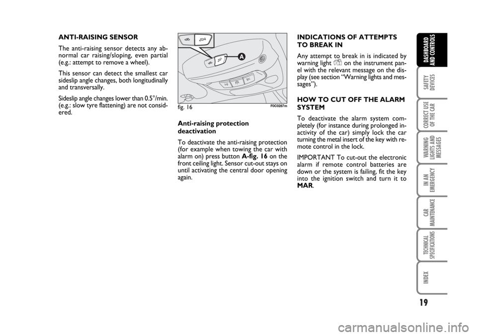
alarm on) press button A-fig. 16 on the
front ceiling light. Sensor cut-out stays on
until activating the central door opening
again.INDICATIONS OF ATTEMPTS
TO BREAK IN
Any attempt to break in is indicated by
warning light
Yon the instrument pan-
el with the relevant message on the dis-
play (see section “Warning lights and mes-
sages”).
HOW TO CUT OFF THE ALARM
SYSTEM
To deactivate the alarm system com-
pletely (for instance during prolonged in-
activity of the car) simply lock the car
turning the metal insert of the key with re-
mote control in the lock.
IMPORTANT To cut-out the electronic
alarm if remote control batteries are
down or the system is failing, fit the key
into the ignition switch and turn it to
MAR.
fig. 16F0C0287m
Page 21 of 274
20
SAFETY
DEVICES
CORRECT USE
OF THE CAR
WARNING
LIGHTS AND
MESSAGES
IN AN
EMERGENCY
CAR
MAINTENANCE
TECHNICAL
SPECIFICATIONS
INDEX
DASHBOARD
AND CONTROLS
IGNITION SWITCH
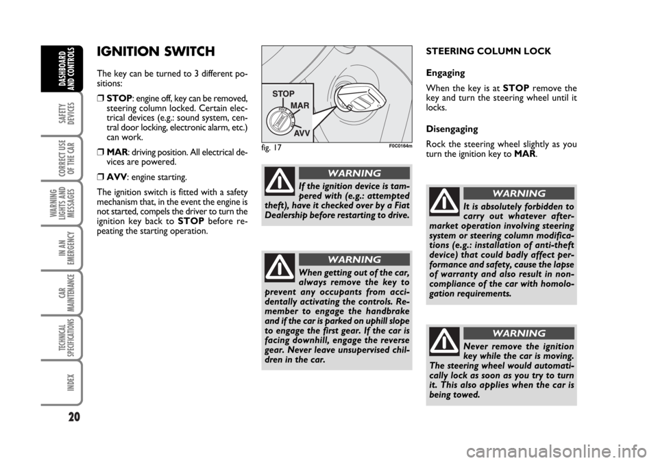
The key can be turned to 3 different po-
sitions:
❒STOP: engine off, key can be removed,
steering column locked. Certain elec-
trical devices (e.g.: sound system, cen-
tral door locking, electronic alarm, etc.)
can work.
❒MAR: driving position. All electrical de-
vices are powered.
❒AVV: engine starting.
The ignition switch is fitted with a safety
mechanism that, in the event the engine is
not started, compels the driver to turn the
ignition key back to STOPbefore re-
peating the starting operation.STEERING COLUMN LOCK
Engaging
When the key is at STOPremove the
key and turn the steering wheel until it
locks.
Disengaging
Rock the steering wheel slightly as you
turn the ignition key to MAR.
fig. 17F0C0164m
If the ignition device is tam-
pered with (e.g.: attempted
theft), have it checked over by a Fiat
Dealership before restarting to drive.
WARNING
When getting out of the car,
always remove the key to
prevent any occupants from acci-
dentally activating the controls. Re-
member to engage the handbrake
and if the car is parked on uphill slope
to engage the first gear. If the car is
facing downhill, engage the reverse
gear. Never leave unsupervised chil-
dren in the car.
WARNING
It is absolutely forbidden to
carry out whatever after-
market operation involving steering
system or steering column modifica-
tions (e.g.: installation of anti-theft
device) that could badly affect per-
formance and safety, cause the lapse
of warranty and also result in non-
compliance of the car with homolo-
gation requirements.
WARNING
Never remove the ignition
key while the car is moving.
The steering wheel would automati-
cally lock as soon as you try to turn
it. This also applies when the car is
being towed.
WARNING
Page 56 of 274

55
SAFETY
DEVICES
CORRECT USE
OF THE CAR
WARNING
LIGHTS AND
MESSAGES
IN AN
EMERGENCY
CAR
MAINTENANCE
TECHNICAL
SPECIFICATIONS
INDEX
DASHBOARD
AND CONTROLS
ALIGNMENT OF SET
TEMPERATURES
(MONO function)
Pressing button MONO automatically
aligns the temperature on the passenger’s
side with that on the driver’s side.
Turn the knob AUTO or MONO to
raise/reduce the temperature between the
two zones by the same value.
Press again button MONO to disable the
function.CLIMATE CONTROL
COMPRESSOR ON/OFF
Press button
❄to switch on the climate
control compressor.
Compressor on
❒button led ❄on;
❒symbol ❄on the display, lit.
Compressor off
❒button led ❄off;
❒symbol ❄on the display, off;
❒inside air recirculation off;
❒AQS function disabled.
With the climate control compressor off,
it is not possible to admit air to the pas-
senger compartment with a temperature
below the outside temperature; in this
case symbol ò flashes on the display.
The switching off of the climate control
compressor remains in storage even when
the engine has been stopped. To restore
automatic control for switching on the cli-
mate control compressor, press button
❄or AUTO, in which case, the other man-
ual settings set will be cancelled.AIR DISTRIBUTION SELECTION
Pressing one or more buttons
Q/E/Zit is possible to choose manually 7 of the
possible air distributions to the passenger
compartment:
QAir flow to the windscreen and
front side window vents to demist
or defrost them.
ZAir flow towards the front and
rear lower parts of the passenger
compartment. This type of distri-
bution allows heating of the pas-
senger compartment in the short-
est time.
Q
ZESplitting of the air flow between
front and rear vents, centre and
side dashboard outlets, rear out-
let, windscreen and front side win-
dow demisting vents.
EAir flow to the dashboard centre
and side outlets (passenger’s
body).
Page 58 of 274
57
SAFETY
DEVICES
CORRECT USE
OF THE CAR
WARNING
LIGHTS AND
MESSAGES
IN AN
EMERGENCY
CAR
MAINTENANCE
TECHNICAL
SPECIFICATIONS
INDEX
DASHBOARD
AND CONTROLS
EXTERNAL LIGHTS
The left-hand stalk controls the external
lights and the direction indicators.
The external lights can only be switched
on when the ignition key is at MAR.
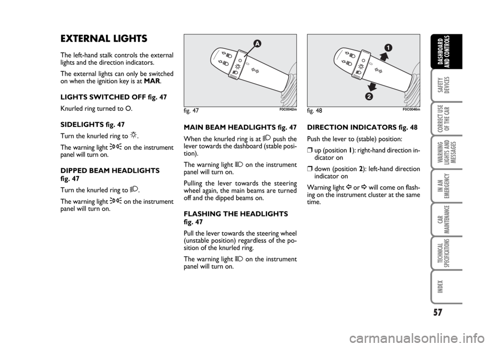
LIGHTS SWITCHED OFF fig. 47
Knurled ring turned to O.
SIDELIGHTS fig. 47
Turn the knurled ring to
6.
The warning light
3on the instrument
panel will turn on.
DIPPED BEAM HEADLIGHTS
fig. 47
Turn the knurled ring to
2.
The warning light
3on the instrument
panel will turn on.MAIN BEAM HEADLIGHTS fig. 47
When the knurled ring is at
2push the
lever towards the dashboard (stable posi-
tion).
The warning light
1on the instrument
panel will turn on.
Pulling the lever towards the steering
wheel again, the main beams are turned
off and the dipped beams on.
FLASHING THE HEADLIGHTS
fig. 47
Pull the lever towards the steering wheel
(unstable position) regardless of the po-
sition of the knurled ring.
The warning light
1on the instrument
panel will turn on.
fig. 47F0C0042mfig. 48F0C0046m
DIRECTION INDICATORS fig. 48
Push the lever to (stable) position:
❒up (position 1): right-hand direction in-
dicator on
❒down (position 2): left-hand direction
indicator on
Warning light
Îor ¥will come on flash-
ing on the instrument cluster at the same
time.
Page 59 of 274
58
SAFETY
DEVICES
CORRECT USE
OF THE CAR
WARNING
LIGHTS AND
MESSAGES
IN AN
EMERGENCY
CAR
MAINTENANCE
TECHNICAL
SPECIFICATIONS
INDEX
DASHBOARD
AND CONTROLS
Direction indicators are switched off au-
tomatically when the steering wheel is
straightened.
If you want the indicator to flash briefly to
show that you are about to change lane,
move the stalk up or down without click-
ing into position (unstable position). When
released the stalk will return to its home
position.
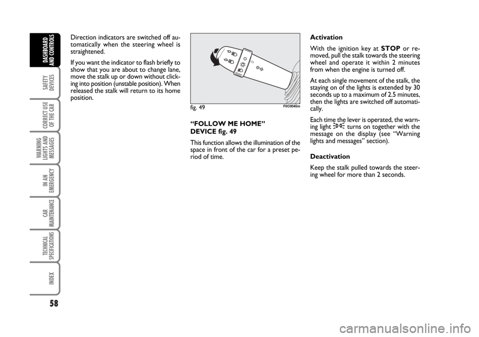
“FOLLOW ME HOME”
DEVICE fig. 49
This function allows the illumination of the
space in front of the car for a preset pe-
riod of time.Activation
With the ignition key at STOPor re-
moved, pull the stalk towards the steering
wheel and operate it within 2 minutes
from when the engine is turned off.
At each single movement of the stalk, the
staying on of the lights is extended by 30
seconds up to a maximum of 2.5 minutes,
then the lights are switched off automati-
cally.
Each time the lever is operated, the warn-
ing light
3turns on together with the
message on the display (see “Warning
lights and messages” section).
Deactivation
Keep the stalk pulled towards the steer-
ing wheel for more than 2 seconds.
fig. 49F0C0045m
Page 62 of 274
61
SAFETY
DEVICES
CORRECT USE
OF THE CAR
WARNING
LIGHTS AND
MESSAGES
IN AN
EMERGENCY
CAR
MAINTENANCE
TECHNICAL
SPECIFICATIONS
INDEX
DASHBOARD
AND CONTROLS
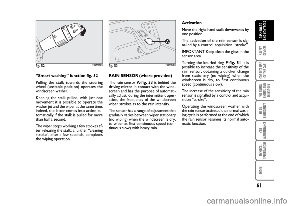
“Smart washing” function fig. 52
Pulling the stalk towards the steering
wheel (unstable position) operates the
windscreen washer.
Keeping the stalk pulled, with just one
movement it is possible to operate the
washer jet and the wiper at the same time;
indeed, the latter comes into action au-
tomatically if the stalk is pulled for more
than half a second.
The wiper stops working a few strokes af-
ter releasing the stalk; a further “cleaning
stroke”, after a few seconds, completes
the wiping operation.RAIN SENSOR (where provided)
The rain sensor A-fig. 53is behind the
driving mirror in contact with the wind-
screen and has the purpose of automati-
cally adjust, during the intermittent oper-
ation, the frequency of the windscreen
wiper strokes as to the rain intensity.
The sensor has a range of adjustment that
gradually varies between wiper stationary
(no wiping) when the windscreen is dry,
to wiper at first continuous speed (con-
tinuous slow) with heavy rain.Activation
Move the right-hand stalk downwards by
one position.
The activation of the rain sensor is sig-
nalled by a control acquisition “stroke”.
IMPORTANT Keep clean the glass in the
sensor area.
Turning the knurled ring F-fig. 51it is
possible to increase the sensitivity of the
rain sensor, obtaining a quicker change
from stationary (no wiping) when the
windscreen is dry, to first continuous
speed (continuous slow).
The increase of the sensitivity of the rain
sensor is signalled by a control and acqui-
sition “stroke”.
Operating the windscreen washer with
the rain sensor activated the normal wash-
ing cycle is performed at the end of which
the rain sensor resumes its normal auto-
matic function.
fig. 52F0C0049mfig. 53F0C0053m
Page 64 of 274

63
SAFETY
DEVICES
CORRECT USE
OF THE CAR
WARNING
LIGHTS AND
MESSAGES
IN AN
EMERGENCY
CAR
MAINTENANCE
TECHNICAL
SPECIFICATIONS
INDEX
DASHBOARD
AND CONTROLS
REAR WINDOW WASHER/
WIPER fig. 54
The device can only work when the igni-
tion key is at MAR.
Pushing the stalk towards the dashboard
(unstable position), the rear window
washer jet and the continuous rear win-
dow wiper operation are activated.
Operation ends when the stalk is released.
Turning the knurled ring Afrom
Oto 'the rear window wiper with intermittent
operation is activated.
fig. 54F0C0047m
HEADLIGHT WASHER fig. 55
Fiat Stilo headlight washers are “re-
tractable”, i.e.: they are located inside the
front bumpers and they are activated (with
dipped beam headlights and/or main beam
headlights on) when the windscreen wash-
er is operated.
IMPORTANT Check at regular intervals
correct operation and cleanness of noz-
zles.
fig. 55F0C0270m
Never use the rear window
wiper to remove ice or snow
from the rear window. In these
conditions, the wiper is sub-
mitted to excessive effort that results
in motor protection cutting in and
wiper operation inhibition for few sec-
onds as a consequence. If operation is
not restored contact Fiat Dealership.
Page 65 of 274
64
SAFETY
DEVICES
CORRECT USE
OF THE CAR
WARNING
LIGHTS AND
MESSAGES
IN AN
EMERGENCY
CAR
MAINTENANCE
TECHNICAL
SPECIFICATIONS
INDEX
DASHBOARD
AND CONTROLS
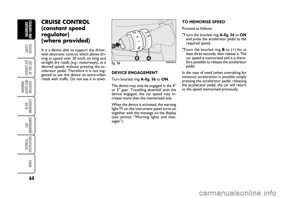
DEVICE ENGAGEMENT
Turn knurled ring A-fig. 56to ON.
The device may only be engaged in the 4
th
or 5thgear. Travelling downhill with the
device engaged, the car speed may in-
crease more than the memorised one.
When the device is activated, the warning
light
Üon the instrument panel turns on
together with the message on the display
(see section “Warning lights and mes-
sages”).TO MEMORISE SPEED
Proceed as follows:
❒turn the knurled ring A-fig. 56to ON
and press the accelerator pedal to the
required speed;
❒turn the knurled ring Bto (+) for at
least three seconds, then release it. The
car speed is memorised and it is there-
fore possible to release the accelerator
pedal.
In the case of need (when overtaking for
instance) acceleration is possible simply
pressing the accelerator pedal: releasing
the accelerator pedal, the car will return
to the speed memorised previously.
fig. 56F0C0127m
CRUISE CONTROL
(constant speed
regulator)
(where provided)
It is a device able to support the driver,
with electronic control, which allows dri-
ving at speed over 30 km/h on long and
straight dry roads (e.g.: motorways), at a
desired speed, without pressing the ac-
celerator pedal. Therefore it is not sug-
gested to use this device on extra-urban
roads with traffic. Do not use it in town.
Page 73 of 274
72
SAFETY
DEVICES
CORRECT USE
OF THE CAR
WARNING
LIGHTS AND
MESSAGES
IN AN
EMERGENCY
CAR
MAINTENANCE
TECHNICAL
SPECIFICATIONS
INDEX
DASHBOARD
AND CONTROLS
CURRENT OUTLET (12V)
The current outlet is located on the cen-
tral console and it only works with igni-
tion key at MAR. If the smokers’ kit is re-
quested, the current outlet will be re-
placed by the cigar lighter (see next para-
graph).
CIGAR LIGHTER
(where provided)
It is located on the central console, at the
side of the handbrake lever.
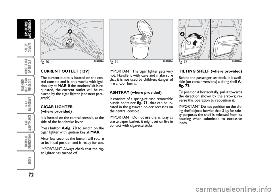
Press button A-fig. 70to switch on the
cigar lighter with ignition key at MAR.
After few seconds the button will return
to its initial position and is ready for use.
IMPORTANT Always check that the cig-
ar lighter has turned off.IMPORTANT The cigar lighter gets very
hot. Handle it with care and make sure
that it is not used by children: danger of
fire and/or burns.
ASHTRAY (where provided)
It consists of a spring-release removable
plastic container fig. 71, that can be lo-
cated in the glass/can holder recesses on
the central console.
IMPORTANT Do not use the ashtray as
waste paper basket: it might set on fire in
contact with cigarette stubs.TILTING SHELF (where provided)
Behind the passenger seatback, it is avail-
able (on certain versions) a tilting shelf A-
fig. 72.
To position it horizontally, pull it towards
the direction shown by the arrows; re-
verse this operation to reposition it.
IMPORTANT Do not position on the tilt-
ing shelf objects heavier than 3 kg: for safe-
ty purposes the shelf is released from its
housing when submitted to excessive
loads.
fig. 70F0C0102mfig. 71F0C0475mfig. 72F0C0076m
Page 76 of 274
75
SAFETY
DEVICES
CORRECT USE
OF THE CAR
WARNING
LIGHTS AND
MESSAGES
IN AN
EMERGENCY
CAR
MAINTENANCE
TECHNICAL
SPECIFICATIONS
INDEX
DASHBOARD
AND CONTROLS
GLASS BLADES OPENING
(knob turning clockwise)
With fully closed roof (curtain and blades),
control knob A-fig. 77at “0”, glass blade
opening affects the curtain opening as fol-
lows:
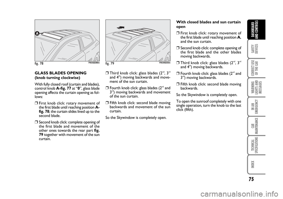
❒First knob click: rotary movement of
the first blade until reaching position A-
fig. 78; the curtain slides lined up to the
second blade.
❒Second knob click: complete opening of
the first blade and movement of the
other ones towards the rear part fig.
79together with movement of the sun
curtain.
❒Third knob click: glass blades (2nd, 3rd
and 4th) moving backwards and move-
ment of the sun curtain.
❒Fourth knob click: glass blades (2ndand
3rd) moving backwards and movement
of the sun curtain.
❒Fifth knob click: second blade moving
backwards and movement of the sun
curtain.
So the Skywindow is completely open.With closed blades and sun curtain
open
❒First knob click: rotary movement of
the first blade until reaching position A,
and the sun curtain.
❒Second knob click: complete opening of
the first blade and the other blades
moving backwards.
❒Third knob click: glass blades (2nd, 3rd
and 4th) moving backwards.
❒Fourth knob click: glass blades (2ndand
3rd) moving backwards.
❒Fifth knob click: second blade moving
backwards.
So the Skywindow is completely open.
To open the sunroof completely with one
single operation, turn the knob to the last
click (fifth).
fig. 78F0C02236mfig. 79F0C00233m