display FIAT TALENTO 2017 Owner handbook (in English)
[x] Cancel search | Manufacturer: FIAT, Model Year: 2017, Model line: TALENTO, Model: FIAT TALENTO 2017Pages: 228, PDF Size: 4.47 MB
Page 56 of 228
IMPORTANT
2)The system uses a coolant that is
compatible with the laws in force in the
countries where the vehicle is sold, R134a
or R1234yf (indicated on a specific plate in
the engine compartment). The use of other
coolants affects the efficiency and condition
of the system. Also the compressor
coolants used must be compatible with the
indicated coolant.
RADAR PARKING
52)
12) 13) 14)
Operating principle
The ultrasound sensors installed in the
rear bumpers (depending on the vehicle
version) "measure" the distance
between the vehicle and an obstacle.
If they detect an obstacle, the sensors
set off an acoustic warning, which
frequency increases when getting
closer to the obstacle, until it becomes
a single sound when the obstacle is
about 30 centimetres from the vehicle.
NOTE Make sure you check that the
ultrasound sensors are not covered
(with dirt, mud, snow, etc.).
NOTE Depending on the versions, the
display lets you see the vehicle's
surrounding area to complement the
acoustic warning signal.Operation
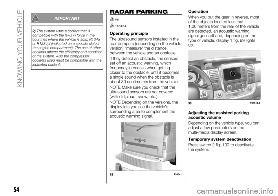
When you put the gear in reverse, most
of the objects located less that
1.20 meters from the rear of the vehicle
are detected, an acoustic warning
signal goes off and, depending on the
type of vehicle, display 1 fig. 99 lights
up.
Adjusting the assisted parking
acoustic volume
Depending on the vehicle type, you can
adjust a few parameters on the
multi-media display screen.
Temporary system deactivation
Press switch 2 fig. 100 to deactivate
the system.
98T36541
99T36519-2
54
KNOWING YOUR VEHICLE
Page 57 of 228
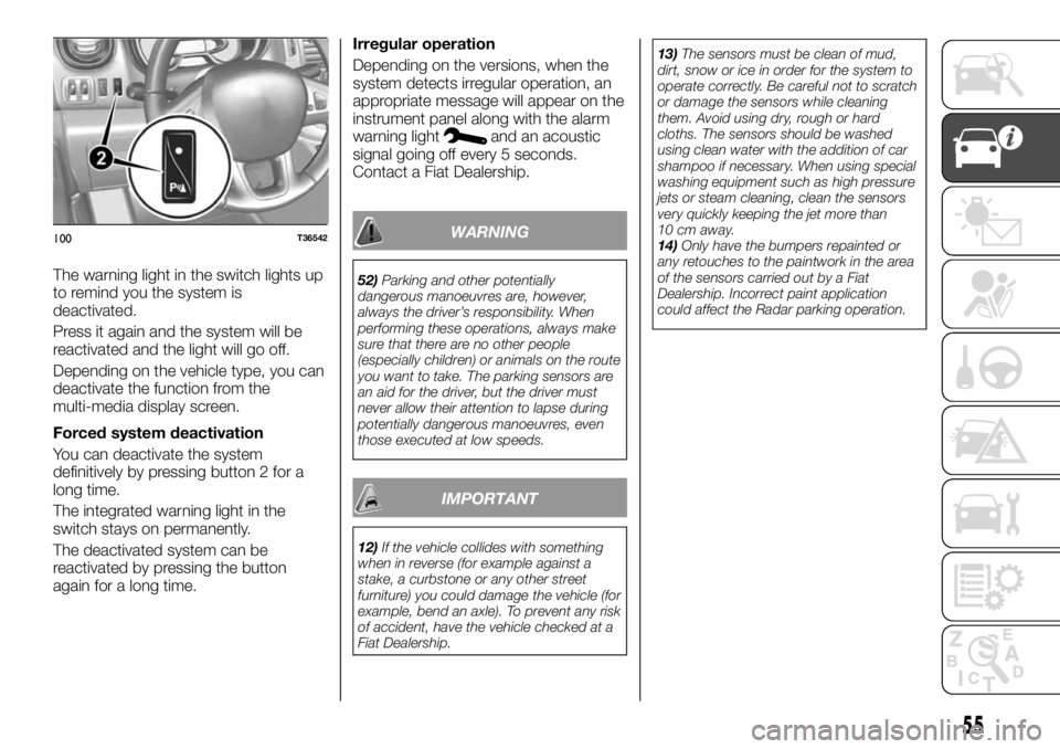
The warning light in the switch lights up
to remind you the system is
deactivated.
Press it again and the system will be
reactivated and the light will go off.
Depending on the vehicle type, you can
deactivate the function from the
multi-media display screen.
Forced system deactivation
You can deactivate the system
definitively by pressing button 2 for a
long time.
The integrated warning light in the
switch stays on permanently.
The deactivated system can be
reactivated by pressing the button
again for a long time.Irregular operation
Depending on the versions, when the
system detects irregular operation, an
appropriate message will appear on the
instrument panel along with the alarm
warning light
and an acoustic
signal going off every 5 seconds.
Contact a Fiat Dealership.
WARNING
52)Parking and other potentially
dangerous manoeuvres are, however,
always the driver’s responsibility. When
performing these operations, always make
sure that there are no other people
(especially children) or animals on the route
you want to take. The parking sensors are
an aid for the driver, but the driver must
never allow their attention to lapse during
potentially dangerous manoeuvres, even
those executed at low speeds.
IMPORTANT
12)If the vehicle collides with something
when in reverse (for example against a
stake, a curbstone or any other street
furniture) you could damage the vehicle (for
example, bend an axle). To prevent any risk
of accident, have the vehicle checked at a
Fiat Dealership.13)The sensors must be clean of mud,
dirt, snow or ice in order for the system to
operate correctly. Be careful not to scratch
or damage the sensors while cleaning
them. Avoid using dry, rough or hard
cloths. The sensors should be washed
using clean water with the addition of car
shampoo if necessary. When using special
washing equipment such as high pressure
jets or steam cleaning, clean the sensors
very quickly keeping the jet more than
10 cm away.
14)Only have the bumpers repainted or
any retouches to the paintwork in the area
of the sensors carried out by a Fiat
Dealership. Incorrect paint application
could affect the Radar parking operation.
100T36542
55
Page 58 of 228
REAR CAMERA
Operation
53)
15)
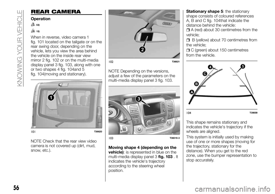
When in reverse, video camera 1
fig. 101 located on the tailgate or on the
rear swing door, depending on the
vehicle, lets you view the area behind
the vehicle on the inside rear view
mirror 2 fig. 102 or on the multi-media
display panel 3 fig. 103, along with one
or two shapes 4 fig. 104and 5
fig. 104(moving and stationary).
NOTE Check that the rear view video
camera is not covered up (dirt, mud,
snow, etc.).NOTE Depending on the versions,
adjust a few of the parameters on the
multi-media display panel 3 fig. 103.
Moving shape 4 (depending on the
vehicle): is represented in blue on the
multi-media display panel 3fig. 103.It
indicates the vehicle's trajectory
according to the steering wheel
position.Stationary shape 5: the stationary
shape consists of coloured references
A, B and C fig. 104that indicate the
distance behind the vehicle:
A (red) about 30 centimetres from the
vehicle;
B (yellow) about 70 centimetres from
the vehicle;
C (green) about 150 centimetres
from the vehicle.
This shape remains stationary and
indicates the vehicle's trajectory if the
wheels are aligned.
This system is initially used by making
use of one or more shapes (moving for
the trajectory, stationary for the
distance). When you get to the red
zone, use the bumper representation to
stop accurately.
101T36620
102T36621
103T36519-3
104T39009
56
KNOWING YOUR VEHICLE
Page 59 of 228
IMPORTANT The display will show a
reversed image. The shapes are a
projected representation on flat ground;
this information has to be ignored when
you superimpose it on a vertical object
or one resting on the ground. The items
that appear on the edge of the screen
can be distorted. If the light is too bright
(snow, vehicle is in sunshine) the video
camera's vision can be disrupted.
When the rear doors are open or not
closed properly, the dedicated message
appears and, depending on the vehicle,
the video camera image disappears.
WARNING
53)Parking and other potentially
dangerous manoeuvres are, however,
always the driver’s responsibility. While
carrying out these manoeuvres, always
make sure that no people (especially
children) or animals are in the area
concerned. The camera is an aid for the
driver, but the driver must never allow
his/her attention to lapse during potentially
dangerous manoeuvres, even those
executed at low speeds. Always keep a
slow speed, so as to promptly brake in the
case of obstacles.
IMPORTANT
15)It is vital, for correct operation, that the
camera is always kept clean and free from
any mud, dirt, snow or ice. Be careful not
to scratch or damage the camera while
cleaning it. Avoid using dry, rough or hard
cloths. The camera must be washed using
clean water, with the addition of car
shampoo if necessary. In washing stations
which use steam or high-pressure jets,
clean the camera quickly, keeping the
nozzle more than 10 cm away from the
sensors. Also, do not apply stickers to the
camera.
ELECTRIC WINDOWS
ELECTRIC WINDOWS
54) 55)
With the starter device inserted:press the button of the window
concerned to lower it to the desired
position;
lift the button of the window
concerned to raise it to the desired
position.
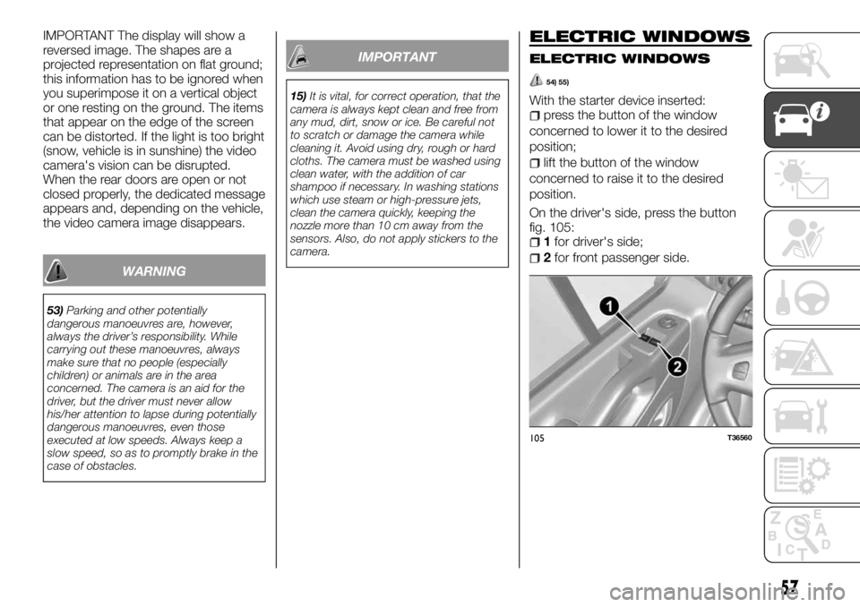
On the driver's side, press the button
fig. 105:
1for driver's side;
2for front passenger side.
105T36560
57
Page 70 of 228
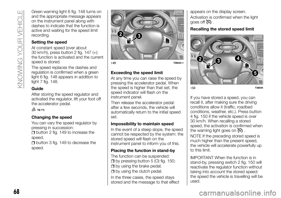
Green warning light 6 fig. 148 turns on
and the appropriate message appears
on the instrument panel along with
dashes to indicate that the function is
active and waiting for the speed limit
recording.
Setting the speed
At constant speed (over about
30 km/h), press button 2 fig. 147 (+):
the function is activated and the current
speed is stored.
The speed replaces the dashes and
regulation is confirmed when a green
light 6 fig. 148 appears in addition to
light 7 fig. 148.
Guide
After storing the speed regulator and
activated the regulator, lift your foot off
the accelerator pedal.
76) 77)
Changing the speed
You can vary the speed regulator by
pressing in succession:
button 2 fig. 149 to increase the
speed.
button 3 fig. 149 to decrease the
speed.Exceeding the speed limit
At any time you can raise the speed by
pressing the accelerator pedal. When
the speed is higher than that set, the
speed indicator will flash on the
instrument panel.
Then release the accelerator pedal:
after a few seconds, the vehicle will
automatically return to the initial speed
set.
Impossibility to maintain speed
In the event of a steep slope, the speed
cannot be respected by the system: the
stored speed will flash on the
instrument panel to inform you of this.
Placing the function in stand-by
The function can be suspended:
by pressing button 5 (O) fig. 150;
by using the brake pedal;
by using the clutch pedal.
In the three cases, the speed stays
stored and the message to that effectappears on the display screen.
Activation is confirmed when the light
goes off
.
Recalling the stored speed limit
If you have stored a speed, you can
recall it, after making sure the driving
conditions allow it (traffic, roadbed
conditions, weather, etc.). Press button
4 fig. 150 if the vehicle speed is over
30 km/h. When recalling a stored
speed, the activation is confirmed when
the warning light goes on
.
NOTE If the preceding stored speed is
much higher than the present speed,
the vehicle will accelerate powerfully up
to this limit.
IMPORTANT When the function is in
stand-by, pressing switch 2 fig. 150 will
reactivate the regulator function without
taking into account the stored speed:
the speed the vehicle is travelling will be
used.
149T36544-1
150T36544
68
KNOWING YOUR VEHICLE
Page 72 of 228
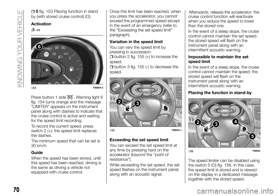
5fig. 153 Placing function in stand
by (with stored cruise control) (O).
Activation
81)
Press button 1 side. Warning light 6
fig. 154 turns orange and the message
"LIMITER" appears on the instrument
panel along with dashes to indicate that
the cruise control is active and waiting
for the speed limit recording.
To record the current speed, press
switch 2 (+): the speed limit replaces
the dashes.
The minimum speed that can be set is
30 km/h.
Guide
When the speed has been stored, until
this speed has been reached, driving is
the same as driving a vehicle not
equipped with cruise control.Once this limit has been reached, when
you press the accelerator, you cannot
exceed the programmed speed except
in the event of an emergency (refer to
the "Exceeding the set speed limit”
paragraph).
Variation in the speed limit
You can vary the speed limit by
pressing in succession:
button 2 fig. 155 (+) to increase the
speed;
button 3 fig. 155 (-) to decrease the
speed.
Exceeding the set speed limit
You can exceed the set speed limit at
any time by pressing hard on the
accelerator (beyond the "point of
resistance").
While exceeding the set speed, the set
speed flashes on the instrument panel,
along with an acoustic signal.Afterwards, release the accelerator: the
cruise control function will reactivate
when you reduce the speed to lower
than the stored one.
In the event of a steep slope, the cruise
control cannot maintain the set speed:
the stored speed will flash on the
instrument panel along with an
intermittent acoustic warning.
Impossible to maintain the set
speed limit
In the event of a steep slope, the cruise
control cannot maintain the speed: the
stored speed will flash on the
instrument panel along with an
intermittent acoustic warning.
Placing the function in stand-by
The speed limiter can be disabled using
the switch 5 (O) fig. 156. In this case,
the speed limit is stored and is viewed
on the display in a dedicated message
together with the stored speed.
154T36504-2
155T36544-1
156T36544
70
KNOWING YOUR VEHICLE
Page 75 of 228
KNOWING THE INSTRUMENT PANEL
This section of the handbook gives you
all the information you need to
understand, interpret and use the
instrument panel correctly.DISPLAY..................75
WARNING LIGHTS............77
CONTROL PANEL AND ON-BOARD
INSTRUMENTS..............85
73
Page 76 of 228
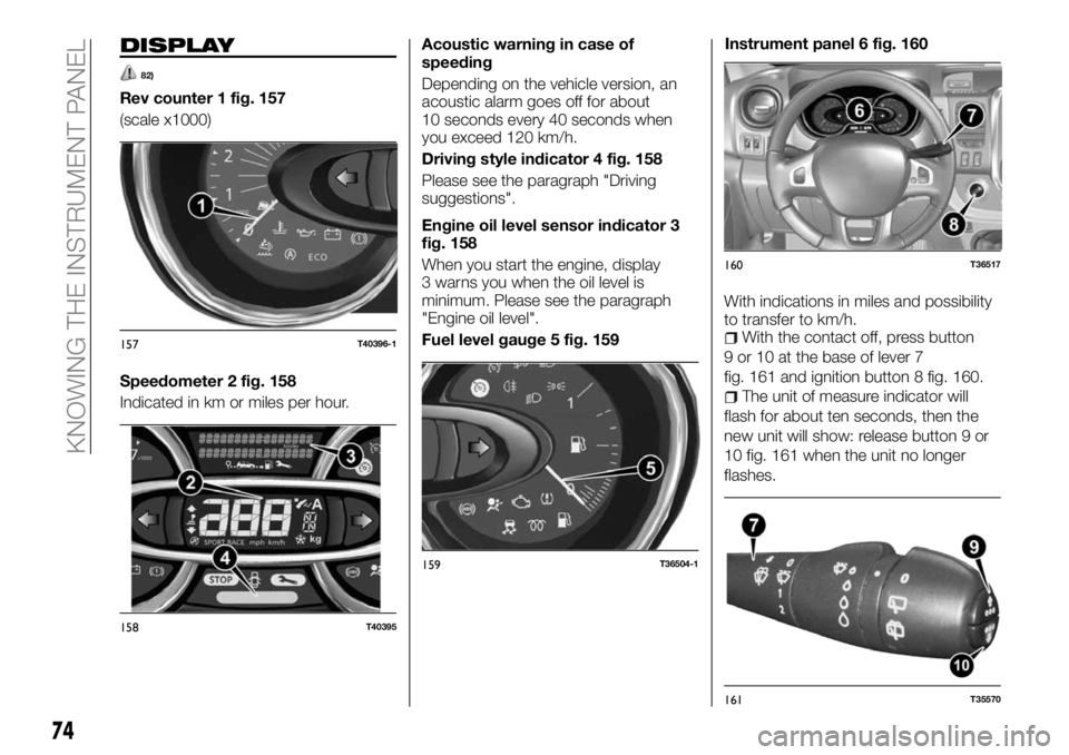
DISPLAY
82)
Rev counter 1 fig. 157
(scale x1000)
Speedometer 2 fig. 158
Indicated in km or miles per hour.Acoustic warning in case of
speeding
Depending on the vehicle version, an
acoustic alarm goes off for about
10 seconds every 40 seconds when
you exceed 120 km/h.
Driving style indicator 4 fig. 158
Please see the paragraph "Driving
suggestions".
Engine oil level sensor indicator 3
fig. 158
When you start the engine, display
3 warns you when the oil level is
minimum. Please see the paragraph
"Engine oil level".
Fuel level gauge 5 fig. 159Instrument panel 6 fig. 160
With indications in miles and possibility
to transfer to km/h.
With the contact off, press button
9 or 10 at the base of lever 7
fig. 161 and ignition button 8 fig. 160.
The unit of measure indicator will
flash for about ten seconds, then the
new unit will show: release button 9 or
10 fig. 161 when the unit no longer
flashes.
157T40396-1
158T40395
159T36504-1
160T36517
161T35570
74
KNOWING THE INSTRUMENT PANEL
Page 77 of 228
To go back to the preceding mode,
repeat the same operation.
NOTE After disconnecting the battery,
the on-board computer automatically
returns to the original unit of measure.
Time and outside temperature
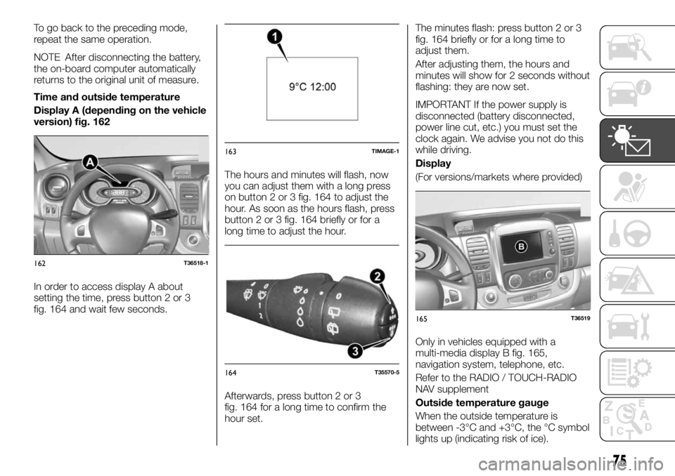
Display A (depending on the vehicle
version) fig. 162
In order to access display A about
setting the time, press button 2 or 3
fig. 164 and wait few seconds.The hours and minutes will flash, now
you can adjust them with a long press
on button 2 or 3 fig. 164 to adjust the
hour. As soon as the hours flash, press
button 2 or 3 fig. 164 briefly or for a
long time to adjust the hour.
Afterwards, press button 2 or 3
fig. 164 for a long time to confirm the
hour set.The minutes flash: press button 2 or 3
fig. 164 briefly or for a long time to
adjust them.
After adjusting them, the hours and
minutes will show for 2 seconds without
flashing: they are now set.
IMPORTANT If the power supply is
disconnected (battery disconnected,
power line cut, etc.) you must set the
clock again. We advise you not do this
while driving.
Display
(For versions/markets where provided)
Only in vehicles equipped with a
multi-media display B fig. 165,
navigation system, telephone, etc.
Refer to the RADIO / TOUCH-RADIO
NAV supplement
Outside temperature gauge
When the outside temperature is
between -3°C and +3°C, the °C symbol
lights up (indicating risk of ice).
162T36518-1
163TIMAGE-1
164T35570-5
165T36519
75
Page 78 of 228
WARNING
82)Since ice formation on roads is due to
various weather factors, such as exposure,
local hygrometry and temperature, it is not
just the outside temperature that indicates
if there is ice or not.
WARNING LIGHTS
83)
18)
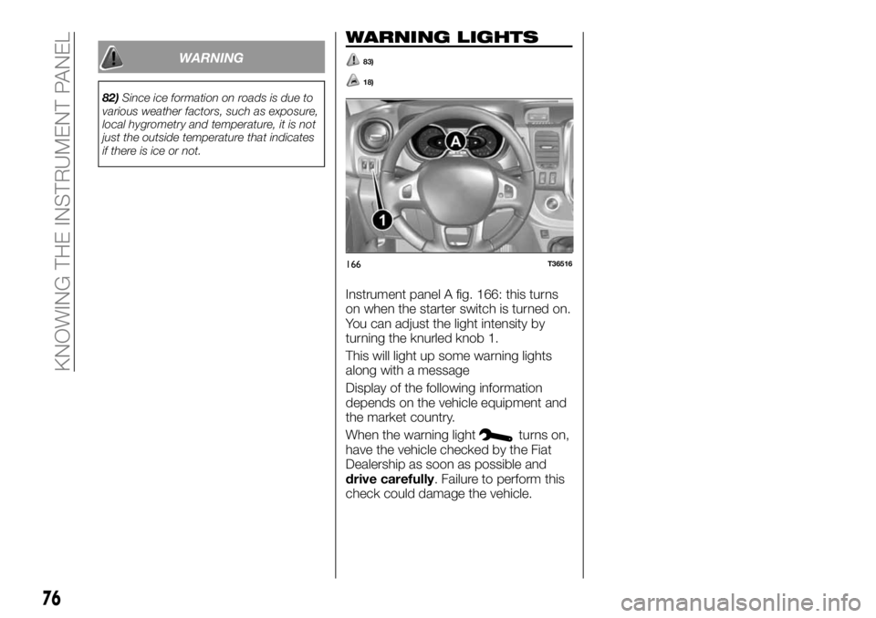
Instrument panel A fig. 166: this turns
on when the starter switch is turned on.
You can adjust the light intensity by
turning the knurled knob 1.
This will light up some warning lights
along with a message
Display of the following information
depends on the vehicle equipment and
the market country.
When the warning light
turns on,
have the vehicle checked by the Fiat
Dealership as soon as possible and
drive carefully. Failure to perform this
check could damage the vehicle.
166T36516
76
KNOWING THE INSTRUMENT PANEL