FIAT TALENTO 2021 Owner handbook (in English)
Manufacturer: FIAT, Model Year: 2021, Model line: TALENTO, Model: FIAT TALENTO 2021Pages: 236, PDF Size: 4.86 MB
Page 151 of 236
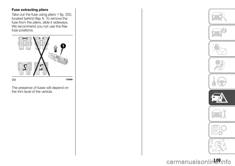
Fuse extracting pliers
Take out the fuse using pliers 1 fig. 255,
located behind flap A. To remove the
fuse from the pliers, slide it sideways.
We recommend you not use the free
fuse positions.
The presence of fuses will depend on
the trim level of the vehicle.
255T32868
149
Page 152 of 236
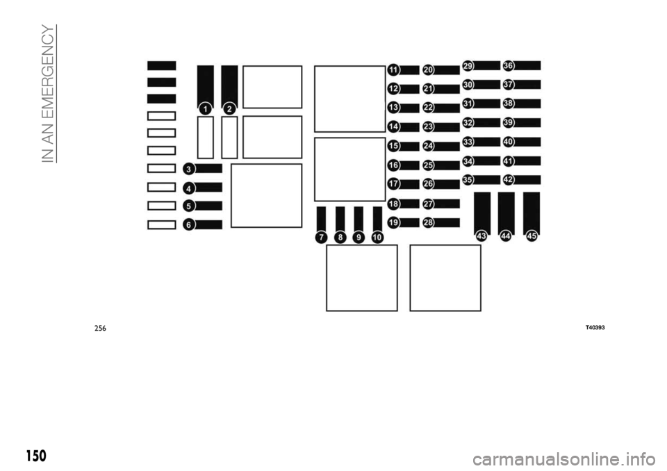
256T40393
150
IN AN EMERGENCY
Page 153 of 236
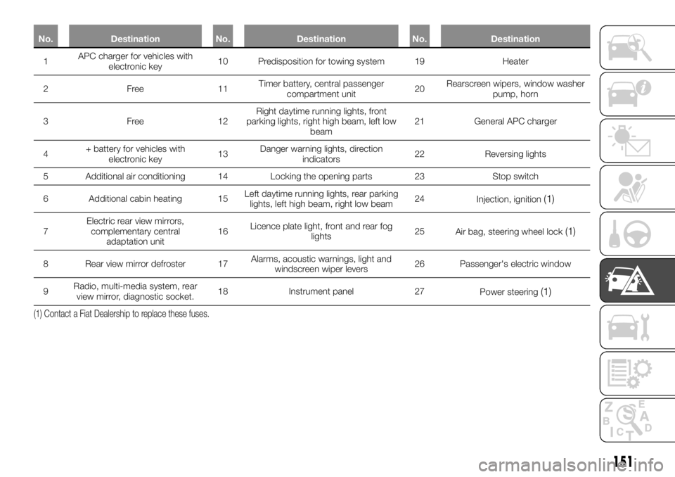
No. Destination No. Destination No. Destination
1APC charger forvehicles with
electronic key10 Predisposition for towing system 19 Heater
2Free11Timer battery, central passenger
compartment unit20Rearscreen wipers, window washer
pump, horn
3Free12Right daytime running lights, front
parking lights, right high beam, left low
beam21 General APC charger
4+ battery for vehicles with
electronic key13Danger warning lights, direction
indicators22 Reversing lights
5 Additional air conditioning 14 Locking the opening parts 23 Stop switch
6 Additional cabin heating 15Left daytime running lights, rear parking
lights, left high beam, right low beam24
Injection, ignition
(1)
7Electric rear view mirrors,
complementary central
adaptation unit16Licence plate light, front and rear fog
lights25
Air bag, steering wheel lock(1)
8 Rear view mirror defroster 17Alarms, acoustic warnings, light and
windscreen wiper levers26 Passenger's electric window
9Radio, multi-media system, rear
view mirror, diagnostic socket.18 Instrument panel 27
Power steering
(1)
(1) Contact a Fiat Dealership to replace these fuses.
151
Page 154 of 236
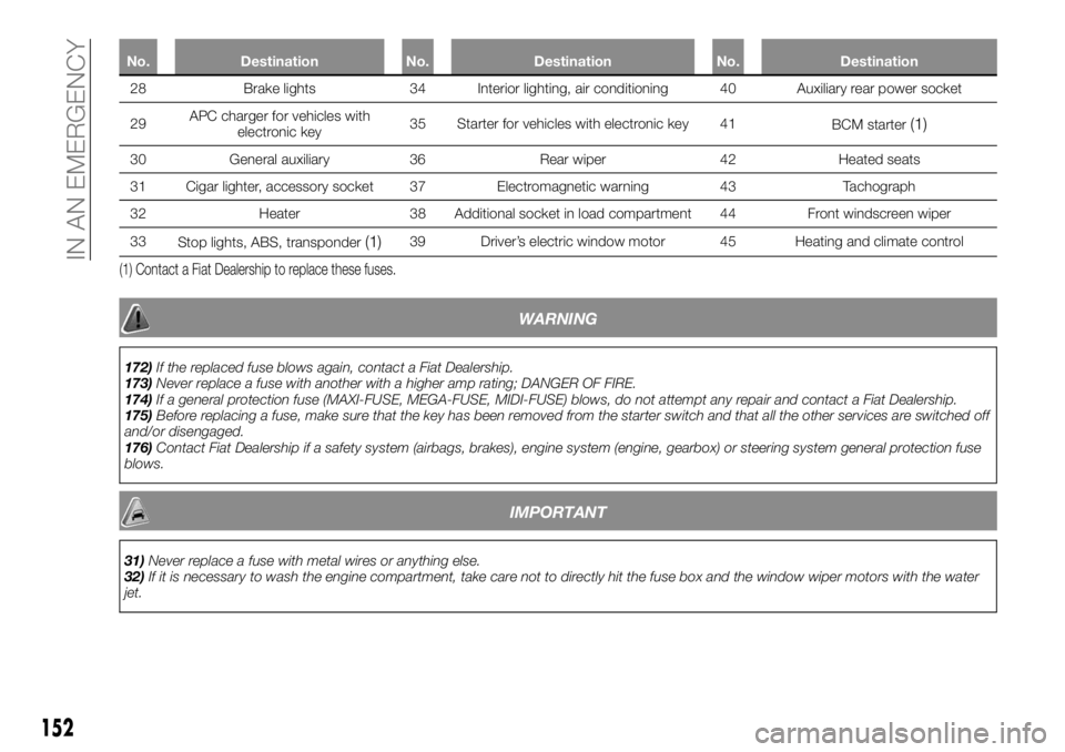
No. Destination No. Destination No. Destination
28 Brake lights 34 Interior lighting, air conditioning 40 Auxiliary rear power socket
29APCcharger for
vehicles with
electronic key35 Starter for vehicles with electronic key 41
BCM starter
(1)
30 General auxiliary 36 Rear wiper 42 Heated seats
31 Cigar lighter, accessory socket 37 Electromagnetic warning 43 Tachograph
32 Heater 38 Additional socket in load compartment 44 Front windscreen wiper
33
Stop lights, ABS, transponder
(1)39 Driver’s electric window motor 45 Heating and climate control
(1) Contact a Fiat Dealership to replace these fuses.
WARNING
172)If the replaced fuse blows again, contact a Fiat Dealership.
173)Never replace a fuse with another with a higher amp rating; DANGER OF FIRE.
174)If a general protection fuse (MAXI-FUSE, MEGA-FUSE, MIDI-FUSE) blows, do not attempt any repair and contact a Fiat Dealership.
175)Before replacing a fuse, make sure that the key has been removed from the starter switch and that all the other services are switched off
and/or disengaged.
176)Contact Fiat Dealership if a safety system (airbags, brakes), engine system (engine, gearbox) or steering system general protection fuse
blows.
IMPORTANT
31)Never replace a fuse with metal wires or anything else.
32)If it is necessary to wash the engine compartment, take care not to directly hit the fuse box and the window wiper motors with the water
jet.
152
IN AN EMERGENCY
Page 155 of 236
IN THE EVENT OF A
PUNCTURE
Depending on the vehicle, there may be
a tyre inflating kit or a spare tyre (see
the following page).
177)
WARNING
177)In case you are stopped by the
carriageway, warn other motorists that your
vehicle is there by placing the warning
triangle or other device allowed by law in
the country you are driving in.
REPLACING A
WHEEL
178) 179) 180) 181) 183) 184) 182)
Tools
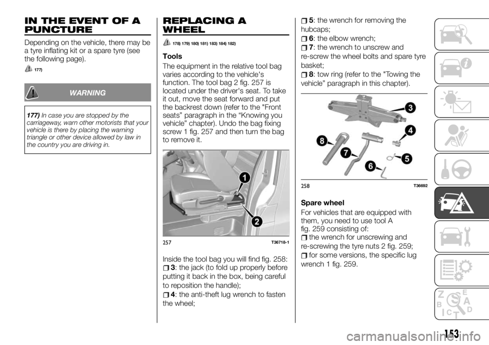
The equipment in the relative tool bag
varies according to the vehicle's
function. The tool bag 2 fig. 257 is
located under the driver's seat. To take
it out, move the seat forward and put
the backrest down (refer to the "Front
seats” paragraph in the “Knowing you
vehicle” chapter). Undo the bag fixing
screw 1 fig. 257 and then turn the bag
to remove it.
Inside the tool bag you will find fig. 258:
3: the jack (to fold up properly before
putting it back in the box, being careful
to reposition the handle);
4: the anti-theft lug wrench to fasten
the wheel;
5: the wrench for removing the
hubcaps;
6: the elbow wrench;
7: the wrench to unscrew and
re-screw the wheel bolts and spare tyre
basket;
8: tow ring (refer to the "Towing the
vehicle” paragraph in this chapter).
Spare wheel
For vehicles that are equipped with
them, you need to use tool A
fig. 259 consisting of:
the wrench for unscrewing and
re-screwing the tyre nuts 2 fig. 259;
for some versions, the specific lug
wrench 1 fig. 259.
257T36718-1
258T36692
153
Page 156 of 236

To extract the spare wheel B fig. 260:with tool A fig. 259 completely undo
nut 5 fig. 260 (right side) and partially
undo nut 3 fig. 260 (left side) in order to
free the basket 4 fig. 260 from nut 3;
free the spare wheel.
Depending on the version, there is
documentation with the instructions
described above in the tool box.
To put spare tyre B fig. 260 back in
place, proceed in the reverse order.
Check that bracket 4 is positioned
correctly before tightening nuts 3 and 5
fig. 260.IMPORTANT In some cases (rear wheel
puncture, vehicle loaded with tow
system) you may need to lift the vehicle
up (from the closest lifting point to the
tyre concerned) to be able to access
the spare tyre.
Wheel plate
Remove wheel plate 9 using wrench 5
fig. 261, inserting the hook in one of the
plate's outside openings.
To refit the plate, position it with respect
to valve 10 fig. 261.
Insert the retaining hooks starting from
the side of valve A, then B and C,
ending with the side opposite valve D
fig. 261.Remove wheel plate 11 fig. 262 with
wrench 5 by inserting the hook in the its
peripheral opening.
To refit it, position the five wheel plate
fasteners corresponding to the 5 fixing
screws fig. 262 and press hard on the
centre of the wheel plate to hook it to
the wheel.
259T36688260T36689261T36693
262T36694
154
IN AN EMERGENCY
Page 157 of 236
Replacing a wheel
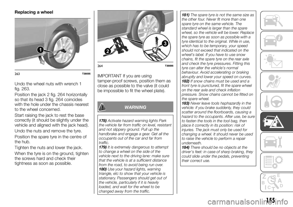
Undo the wheel nuts with wrench 1
fig. 263.
Position the jack 2 fig. 264 horizontally
so that its head 3 fig. 264 coincides
with the hole under the chassis nearest
to the wheel concerned.
Start raising the jack to rest the base
correctly (it should be slightly under the
vehicle and aligned with the jack head).
Undo the nuts and remove the tyre.
Position the spare tyre in the centre of
the hub.
Tighten the nuts and lower the jack.
When the tyre is on the ground, tighten
the screws hard and check their
tightness as soon as possible.IMPORTANT If you are using
tamper-proof screws, position them as
close as possible to the valve (it could
be impossible to fit the wheel plate).
WARNING
178)Activate hazard warning lights Park
the vehicle far from traffic on level, resistant
and not slippery ground. Pull up the
handbrake and engage a gear. Get all the
occupants out of the car and far from
traffic.
179)It is extremely dangerous to attempt
to change a wheel on the side of the
vehicle next to the driving lane: make sure
that the vehicle is at a sufficient distance
from the road, to avoid being run over.
180)Use your hazard lights, warning
triangle, etc to show that your vehicle is
stationary. Passengers should get out of
the vehicle, particularly if it is heavily
loaded, and wait for the wheel to be
changed away from the traffic.181)The spare tyre is not the same size as
the other four. Never fit more than one
spare tyre on the same vehicle. The
standard wheel is larger than the spare
wheel, so the vehicle will be lower. Replace
the spare tyre as soon as possible with a
tyre identical to the original. While in use,
which has to be temporary, your speed
should not exceed that indicated on the
wheel's label. If you have to use snow
chains, fit the spare tyre on the rear axle
and check the tyre pressures. Fitting this
tyre can alter the vehicle's normal
behaviour. Avoid accelerating or braking
abruptly and lower your speed on curves.
182)If snow chains must be used and a
front tyre is punctured, fit the spare wheel
on the rear axle and check inflation
pressure. Snow chains cannot be fitted on
the spare wheel.
183)Never leave tools haphazardly in the
vehicle: if you brake suddenly, they could
scatter around the floorboards, causing a
hazard to the occupants. After use, be sure
to fasten the tools in the tool bag, then
place it correctly in its position: risk of
injuries. The jack must only be used for
changing a wheel. It should never be used
to raise the vehicle to perform a repair
underneath.
184)There should be no objects at the
driver's feet: in case of sharp braking, they
could slide under the pedals, preventing
their correct use.
263T36695
264T36696
155
Page 158 of 236
TYRE INFLATION KIT
185)
33) 34) 35) 36) 37) 38) 39)
To take the kit out, move the seat as far
forward as possible and lower the
backrest.
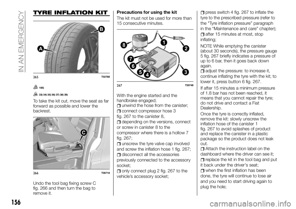
Undo the tool bag fixing screw C
fig. 266 and then turn the bag to
remove it.Precautions for using the kit
The kit must not be used for more than
15 consecutive minutes.
With the engine started and the
handbrake engaged;unwind the hose from the canister;
connect compressor hose 3
fig. 267 to the canister 8,
depending on the versions, connect
or screw in canister 8 to the
compressor where there is a hollow 7
fig. 267;
unscrew the tyre valve cap involved
and screw the inflation hose 1 fig. 267;
disconnect all the accessories
previously connected to the accessory
socket;
only connect plug 2 fig. 267 to the
vehicle’s accessory socket;
press switch 4 fig. 267 to inflate the
tyre to the prescribed pressure (refer to
the "Tyre inflation pressure” paragraph
in the “Maintenance and care” chapter);
after 15 minutes at most, stop
inflating;
NOTE While emptying the canister
(about 30 seconds), the pressure gauge
5 fig. 267 briefly indicates a pressure of
up to 6 bar, then it goes back down
again.
adjust the pressure: to increase it,
continue inflating the tyre with the kit; to
lower it, press button 6 fig. 267.
If after 15 minutes a minimum pressure
of 1.8 bar has not been reached, it
means that you cannot repair the tyre;
do not drive and contact a Fiat
Dealership.
Once the tyre is correctly inflated,
remove the kit: slowly unscrew the
inflation hose of the canister 1
fig. 267 to avoid splashes of product
and replace the canister in a plastic
package so the product does not leak
out.
Attach the instruction label on the
dashboard where the driver can see it;
replace the kit in the tool bag and put
it back under the driver's seat;
when the first inflation has been
done, the tyre will continue to lose air
and you need to start driving again to
plug the hole;
265T32788
266T36718
267T35749
156
IN AN EMERGENCY
Page 159 of 236
leave immediately and drive at a
speed between 20 and 60 km/h to
uniformly distribute the product on the
tyre and, after 3 kilometres, stop to
check the pressure;
if the pressure is greater than 1.3 bar
but less than prescribed, you need to
adjust it (see the label attached to the
driver's door pillar), otherwise see a Fiat
Dealership: you cannot repair it.
WARNING
185)There should be no objects at the
driver's feet: in case of sharp braking, they
could slide under the pedals, preventing
their correct use.
IMPORTANT
33)The kit can repair tyres whose treads A
fig. 265 are damaged by foreign objects
smaller than 4 millimetres. It cannot repair
all types of puncture, such as cuts larger
than 4 millimetres and those on side B
fig. 265 of the tyre. Also make sure the rims
are in good condition. Do not remove the
foreign object that caused the puncture if it
is implanted in the tyre.34)Do not use the inflation kit if the tyre is
damaged by driving with a puncture. Check
the tyre sides carefully before any
intervention. Travelling with partially or
completely deflated tyres (or punctured)
can cause safety problems and damage
the concerned tyre beyond repair. This
reparation is temporary. A tyre that has
been punctured must be examined (and
repaired if possible) by a specialist as soon
as possible. When replacing a tyre repaired
by the kit, always notify the tyre repairer.
When driving, you can feel vibrations
caused by the product being in the tyre.
35)The kit is approved only for inflating
tyres of vehicles that were originally
equipped with it. It should never be used to
inflate another vehicle's tyres or any other
object (life vests, inflatable mattresses,
etc.). Use the repair canister with great care
to prevent getting splashes of product on
the skin. If the product comes in contact
with skin, rinse thoroughly. Do not leave the
repair kit within the reach of children. Do
not leave empty canister in the
environment. Deliver it to a Fiat Dealership
or to a consortium specialised in its
disposal. The canister has an expiration
date indicated on the label. Check the
expiration date. Go to a Fiat Dealership to
replace the inflation hose and repair
canister.
36)Before using the kit, park the vehicle so
it is sufficiently far from traffic, turn on the
emergency lights, pull up the handbrake
and get all the occupants out of the vehicle,
moving them far away from the traffic.37)In case you are stopped by the
carriageway, warn other road users that
your vehicle is there by placing the warning
triangle or other device allowed by law in
the country you are driving in.
38)Caution, a missing or badly screwed on
valve cap could impact the tyre's grip and
cause a loss of pressure. The valve caps
must all be identical to the original ones
and screwed tightly.
39)After repair using the kit, do not drive
farther than 200 km. In addition, lower your
speed, and in any case do not exceed
80 km/h. The label is to be attached in a
visible part of the dashboard. Depending
on the market country or local laws, a tyre
repaired with the inflation kit must be
replaced.
157
Page 160 of 236
JUMP STARTING
186) 187) 188) 189) 190)
40)
Starting the engine that supplies
electrical power and keeping it at
medium speed.
To start, if you use the battery from
another vehicle, you need to have the
right cables (large size) from a Fiat
Dealership or, if you already have them,
make sure they are in perfect condition.
The two batteries have to have nominal
identical voltage: 12 Volt The battery
that supplies the power has to have a
capacity (amperes/hour, Ah) that is at
least identical to the dead battery.
Make sure that there is no contact
between the two vehicles (risk of short
circuit at the moment the positive poles
are in contact) and that the dead
battery is well connected. Disengage
the starter device.Depending on the versions, unhook the
battery guard.
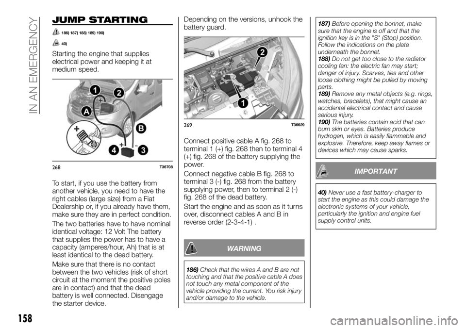
Connect positive cable A fig. 268 to
terminal 1 (+) fig. 268 then to terminal 4
(+) fig. 268 of the battery supplying the
power.
Connect negative cable B fig. 268 to
terminal 3 (-) fig. 268 from the battery
supplying power, then to terminal 2 (-)
fig. 268 of the dead battery.
Start the engine and as soon as it turns
over, disconnect cables A and B in
reverse order (2-3-4-1) .
WARNING
186)Check that the wires A and B are not
touching and that the positive cable A does
not touch any metal component of the
vehicle providing the current. You risk injury
and/or damage to the vehicle.187)Before opening the bonnet, make
sure that the engine is off and that the
ignition key is in the "S" (Stop) position.
Follow the indications on the plate
underneath the bonnet.
188)Do not get too close to the radiator
cooling fan: the electric fan may start;
danger of injury. Scarves, ties and other
loose clothing might be pulled by moving
parts.
189)Remove any metal objects (e.g. rings,
watches, bracelets), that might cause an
accidental electrical contact and cause
serious injury.
190)The batteries contain acid that can
burn skin or eyes. Batteries produce
hydrogen, which is easily flammable and
explosive. Therefore, keep away flames or
devices which may cause sparks.
IMPORTANT
40)Never use a fast battery-charger to
start the engine as this could damage the
electronic systems of your vehicle,
particularly the ignition and engine fuel
supply control units.
268T36708
269T36629
158
IN AN EMERGENCY