sensor FIAT TEMPRA 1988 Service And Owner's Manual
[x] Cancel search | Manufacturer: FIAT, Model Year: 1988, Model line: TEMPRA, Model: FIAT TEMPRA 1988Pages: 171, PDF Size: 18.05 MB
Page 116 of 171
over stop and will also reach its 'maximum speed' stop with
the pedal fully depressed.
Job 8. Mechanical fuel pump,
petrol engine (carburettored) -
replacement.
O Step 1: Disconnect the battery earth lead.
• Step 2: Find the pump on the forward facing side of the
cylinder block near the timing cover end. Disconnect the two
fuel lines from the pump and plug the ends, (labelling them
for correct refitment).
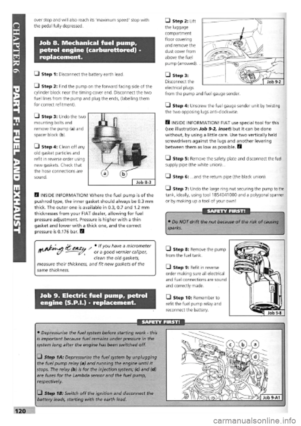
• Step 3: Undo the two
mounting bolts and
remove the pump (a) and
spacer block (b).
• Step 4: Clean off any
old gasket particles and
refit in reverse order using
new gaskets. Check that
the hose connections are
sound.
D INSIDE INFORMATION! Where the fuel pump is of the
pushrod type, the inner gasket should always be 0.3 mm
thick. The outer one is available in 0.3, 0.7 and 1.2 mm
thicknesses from your FIAT dealer, allowing for fuel
pressure adjustment. Pressure is higher with a thin
gasket and lower with a thick one, and the correct
pressure is 0.176 bar. Q
/ # lfyou h"ve a m/cromefer
ff (y - or a good vernier caliper,
clean the old gaskets,
measure their thickness, and fit new gaskets of the
same thickness.
Job 9. Electric fuel pump, petrol
engine (S.P.I.) - replacement.
• Step 2: Lift
the luggage
compartment
floor covering
and remove the
dust cover from
above the fuel
pump (arrowed). .
• Step 3:
Disconnect the
electrical plugs
from the pump and fuel gauge sender.
• Step 4: Unscrew the fuel gauge sender unit by twisting
the two opposing lugs anti-clockwise.
D INSIDE INFORMATION! FIAT use special tool for this
(see illustration Job
9-2,
inset) but it can be done
without, by using a little care. Use two vertically held
screwdrivers against the lugs and another levering
between them as low as possible. H
Q Step 5: Remove the safety plate and disconnect the fuel
supply pipe (the white union)...
Q Step 6: ...and the return pipe (the black union).
1-1 Step 7: Undo the large ring nut securing the pump to the
tank, ideally, using tool 1854041000 and a polygonal spanner
or by making up a tool of your own!
SAFETY FIRST!
• Do NOT drift the nut because of the risk of
causing
sparks.
Q Step 8: Remove the pump
from the fuel tank.
Q Step 9: Refit in reverse
order making sure all electrical
and fuel connections are sound
and correctly made.
• Step 10: Remember to
refit the fuel pump relay and
reconnect the battery.
SAFETY FIRST!
• Depressurise the fuel system before starting work
-
this
is important because fuel remains under pressure in the
system long after the engine has been switched off.
• Step 1A: Depressurise the fuel system by unplugging
the fuel pump relay (a) and running the engine until it
stops. The relay (b) is for the injection system; (c) and (d)
are fuses for the Lambda sensor and the fuel pump,
respectively.
• Step 1B: Switch off the ignition and disconnect the
battery leads, starting with the earth lead.
Page 117 of 171
Job 10. Fuel tank - removal and
refitting.
Job 11. Hot air hoses/thermo-
valves - general.
SAFETY FIRST!
Job 12. Lambda sensor
(S.P.I, engines) - replacement.
• We recommend that you carry out all of this work
out of
doors.
I
IMPORTANT NOTE:
• Read Chapter 1, Safety First! before carrying out
this
work!
• Plan ahead! Run the fuel in the tank as low as possible
before you start this job.
Q Step 1: Disconnect the battery leads starting with the
earth lead.
• Step 2: Syphon any remaining fuel from the tank and
into a suitable closed container.
Q Step 3: Disconnect the fuel sender wiring and any fuel
hoses
from within the boot (model-dependent
-
see Job 9 and
PARTE: ELECTRICAL AND INSTRUMENTS, Job 14).
• Step 4: Disconnect the filler and breather hoses from the
tank,
working from underneath the car.
a - Lambda sensor b - connector to ECU c - sensor heater power supply Job 12-2
Q Step 5: Support the tank while undoing the strap
securing bolts at the rear of the tank...
Q Step 6: ...and at the front.
Q Step 7: Lower the tank a very small amount at a time,
enough to check whether any hoses remain attached, then
lower it fully to the ground.
Q Step 8: Refit in the reverse order, making sure all connec-
tions are
sound. Reconnect the battery leads.
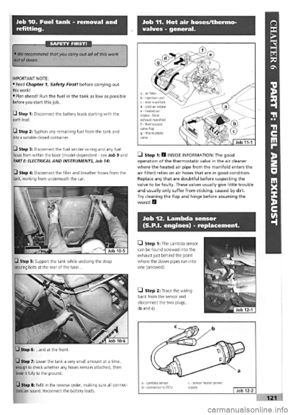
• Step 1: H INSIDE INFORMATION: The good
operation of the thermostatic valve in the air cleaner
where the heated air pipe from the manifold enters the
air filter) relies on air hoses that are in good condition.
Replace any that are doubtful before suspecting the
valve to be faulty. These valves usually give little trouble
and usually only suffer from sticking, caused by dirt.
Try cleaning the flap and hinge before assuming the
worst! Q
• Step 1: The Lambda sensor
can be found screwed into the
exhaust just behind the point
where the down pipes run into
one (arrowed).
Q Step 2: Trace the wiring
back from the sensor and
disconnect the two plugs,
(b and c).
a - air filter b - injection unit c - inlet manifold d - cool air intake e - heated air intake - from exhaust manifold f
-
thermostatic valve flap g - thermostatic valve
Job 11-1
Page 118 of 171
Job 14. Exhaust system -
replacement.
FACT FILE: LAMBDA SENSOR
• The Lambda sensor is very fragile and
should not be knocked or dropped.
• We recommend that a new one is fitted
only by your FIAT dealer, who can test the
old one to see whether it is working properly.
• No cleaners should be used on the sensor.
Q Step 3: Before refitting, check that the sensor sealing ring
is in good condition, and lubricate the thread of the sensor
with a high-temperature anti-seize compound.
Job 13. Fuel evaporation system.
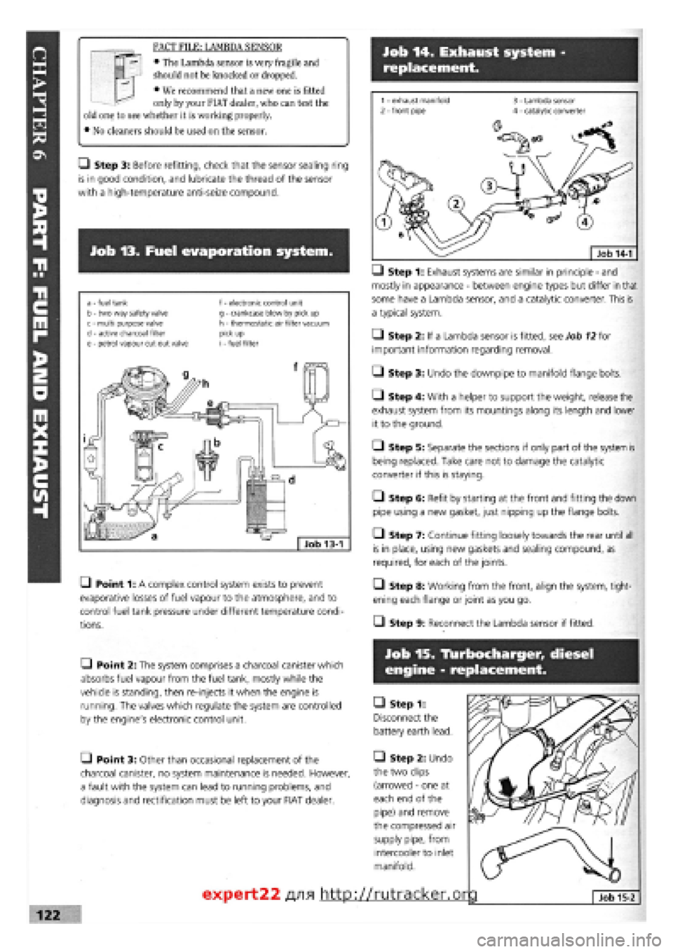
a - fuel tank b - two way safety valve c - multi purpose valve d
-
active charcoal filter e - petrol vapour cut out valve
f - electronic control unit g - crankcase blow by pick up h - thermostatic air filter vacuum pick up i - fuel filter
• Point 1: A complex control system exists to prevent
evaporative losses of fuel vapour to the atmosphere, and to
control fuel tank pressure under different temperature condi-
tions.
—) Step 1: Exhaust systems are similar in principle
-
and
mostly in appearance
-
between engine types but differ in that
some have a Lambda sensor, and a catalytic converter. This is
a typical system.
• Step 2: If a Lambda sensor is fitted, see Job
12
for
important information regarding removal.
• Step 3: Undo the downpipe to manifold flange bolts.
• Step 4: With a helper to support the weight, release the
exhaust system from its mountings along its length and lower
it to the ground.
O Step 5: Separate the sections if only part of the system is
being replaced. Take care not to damage the catalytic
converter if this is staying.
• Step 6: Refit by starting at the front and fitting the down
pipe using a new gasket, just nipping up the flange bolts.
• Step 7: Continue fitting loosely towards the rear until all
is in place, using new gaskets and sealing compound, as
required, for each of the joints.
• Step 8: Working from the front, align the system, tight-
ening each flange or joint as you go.
• Step 9: Reconnect the Lambda sensor if fitted.
• Point 2: The system comprises a charcoal canister which
absorbs fuel vapour from the fuel tank, mostly while the
vehicle is standing, then re-injects it when the engine is
running. The valves which regulate the system are controlled
by the engine's electronic control unit.
• Point 3: Other than occasional replacement of the
charcoal canister, no system maintenance is needed. However,
a fault with the system can lead to running problems, and
diagnosis and rectification must be left to your FIAT dealer.
Job 15. Tlurbocharger, diesel
engine - replacement.
• Step 1:
Disconnect the
battery earth lead.
• Step 2: Undo
the two clips
(arrowed
-
one at
each end of the
pipe) and remove
the compressed air
supply pipe, from
intercooler to inlet
manifold.
expert22 fl/i* http://rutracker.or
Page 130 of 171
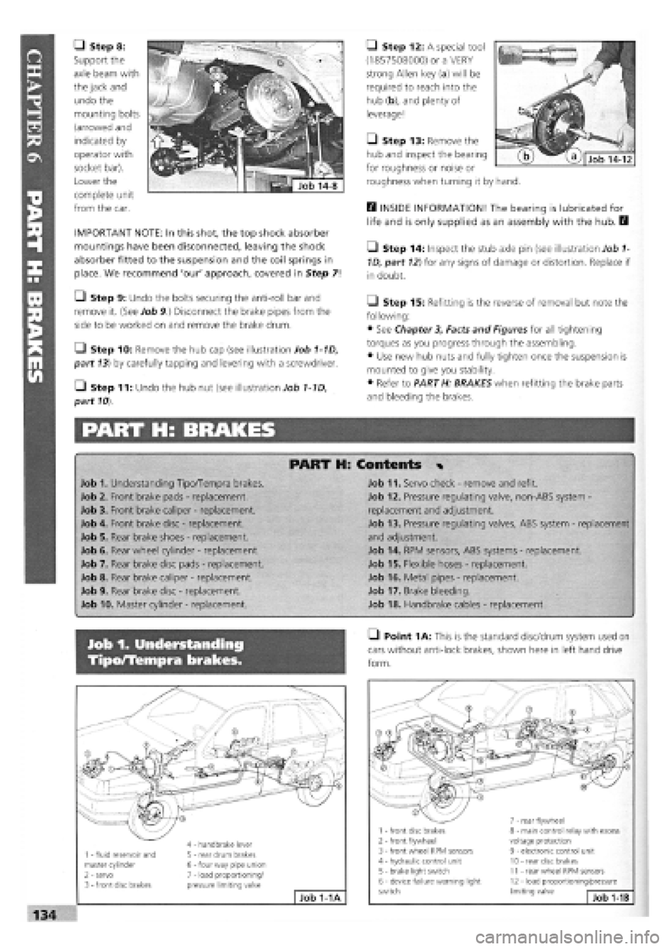
• Step 8:
Support the
axle beam with
the jack and
undo the
mounting bolts
(arrowed and
indicated by
operator with
socket bar).
Lower the
complete unit
from the car.
IMPORTANT NOTE: In this shot, the top shock absorber
mountings have been disconnected, leaving the shock
absorber fitted to the suspension and the coil springs in
place. We recommend 'our' approach, covered in Step 7!
• Step 9: Undo the bolts securing the anti-roll bar and
remove it. (See Job 9.) Disconnect the brake pipes from the
side to be worked on and remove the brake drum.
Q Step 10: Remove the hub cap (see illustration Job 1-1D,
part 13) by carefully tapping and levering with a screwdriver.
• Step 11: Undo the hub nut (see illustration Job 1-1D,
part
10).
PART H: BRAKES
• Step 12: A special tool
(1857508000) or a VERY
strong Allen key (a) will be
required to reach into the
hub (b), and plenty of
leverage!
Q Step 13: Remove the
hub and inspect the bearing
for roughness or noise or
roughness when turning it by hand.
E3 INSIDE INFORMATION! The bearing is lubricated for
life and is only supplied as an assembly with the hub. B
• Step 14: Inspect the stub axle pin (see illustration Job
1-
1D, part
12)
for any signs of damage or distortion. Replace if
in doubt.
Q Step 15: Refitting is the reverse of removal but note the
following:
• See Chapter
3,
Facts and Figures for all tightening
torques as you progress through the assembling.
• Use new hub nuts and fully tighten once the suspension is
mounted to give you stability.
• Refer to PART H: BRAKES when refitting the brake parts
and bleeding the brakes.
PART H: Contents %
Job 1. Understanding Tipo/Tempra brakes.
Job 2. Front brake pads
-
replacement.
Job 3. Front brake caliper
-
replacement.
Job 4. Front brake disc
-
replacement.
Job 5. Rear brake shoes
-
replacement.
Job 6. Rear wheel cylinder
-
replacement.
Job 7. Rear brake disc pads
-
replacement.
Job 8. Rear brake caliper
-
replacement.
Job 9. Rear brake disc
-
replacement.
Job 10. Master cylinder
-
replacement.
Job 11. Servo check
-
remove and refit.
Job 12. Pressure regulating valve, non-ABS system -
replacement and adjustment.
Job 13. Pressure regulating valves, ABS system
-
replacement
and adjustment.
Job 14. RPM sensors, ABS systems
-
replacement.
Job 15. Flexible hoses
-
replacement.
Job 16. Metal pipes
-
replacement.
Job 17. Brake bleeding.
Job 18. Handbrake cables
-
replacement.
Job 1. Understanding
Tipo/Tempra brakes.
• Point
1
A: This is the standard disc/drum system used on
cars without anti-lock brakes, shown here in left hand drive
form.
1 - fluid reservoir and master cylinder 2 - servo 3
-
front disc brakes
4 - handbrake lever 5 - rear drum brakes 6
-
four way pipe union 7 - load proportioning/ pressure limiting valve
Job 1-1A
1 - front disc brakes 2
-
front flywheel 3 - front wheel RPM sensors 4 - hydraulic control unit 5 - brake light switch 6 - device failure warning light switch
7 - rear flywheel 8 - main control relay with excess voltage protection 9 - electronic control unit 10 - rear disc brakes 11 - rear wheel RPM sensors 12 - load proportioning/pressure limiting valve Job
1-1B
Page 131 of 171
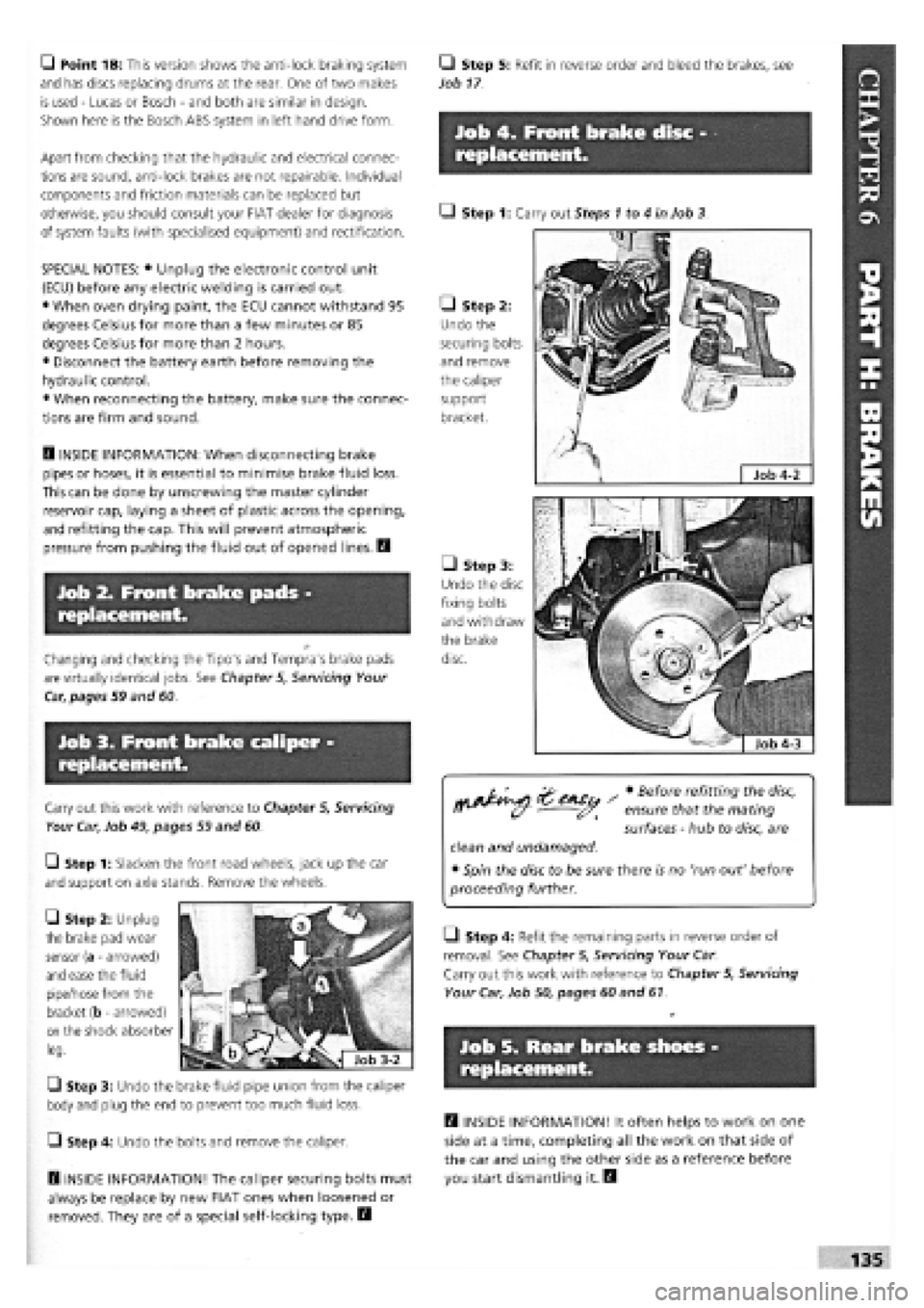
Q Point 1B: This version shows the anti-lock braking system
and has discs replacing drums at the rear. One of two makes
is used
-
Lucas or Bosch
-
and both are similar in design.
Shown here is the Bosch ABS system in left hand drive form.
Apart from checking that the hydraulic and electrical connec-
tions are sound, anti-lock brakes are not repairable. Individual
components and friction materials can be replaced but
otherwise, you should consult your FIAT dealer for diagnosis
of system faults (with specialised equipment) and rectification.
SPECIAL NOTES: • Unplug the electronic control unit
(ECU) before any electric welding is carried out.
• When oven drying paint, the ECU cannot withstand 95
degrees Celsius for more than a few minutes or 85
degrees Celsius for more than 2 hours.
• Disconnect the battery earth before removing the
hydraulic control.
• When reconnecting the battery, make sure the connec-
tions are firm and sound.
Q INSIDE INFORMATION: When disconnecting brake
pipes or hoses, it is essential to minimise brake fluid loss.
This can be done by unscrewing the master cylinder
reservoir cap, laying a sheet of plastic across the opening,
and refitting the cap. This will prevent atmospheric
pressure from pushing the fluid out of opened lines. D
Job 2. Front brake pads -
replacement.
Changing and checking the Tipo's and Tempra's brake pads
are virtually identical jobs. See Chapter 5, Servicing Your
Car, pages 59 and 60
Job 3. Front brake caliper -
replacement.
Carry out this work with reference to Chapter 5, Servicing
Your Car, Job 49, pages 59 and 60.
Q Step 1: Slacken the front road wheels, jack up the car
and support on axle stands. Remove the wheels.
Q Step 2: Unplug
the brake pad wear
sensor (a
-
arrowed)
and ease the fluid
pipe/hose from the
bracket (b
-
arrowed)
on
the shock absorber
leg.
Q Step 3: Undo the brake fluid pipe union from the caliper
body and plug the end to prevent too much fluid loss.
Q Step 4: Undo the bolts and remove the caliper.
D INSIDE INFORMATION! The caliper securing bolts must
always be replace by new FIAT ones when loosened or
removed. They are of a special self-locking type. B
Q Step 5: Refit in reverse order and bleed the brakes, see
Job 17
Job 4. Front brake disc -
replacement.
Q Step 1: Carry out Steps 1 to 4 in Job 3.
• Step 2:
Undo the
securing bolts
and remove
the caliper
support
bracket.
• Step 3:
Undo the disc
fixing bolts
and withdraw
the brake
disc.
Q Step 4: Refit the remaining parts in reverse order of
removal. See Chapter 5, Servicing Your Car.
Carry out this work with reference to Chapter 5, Servicing
Your Car, Job 50, pages 60 and 61.
Job 5. Rear brake shoes -
replacement.
H INSIDE INFORMATION! It often helps to work on one
side at a time, completing all the work on that side of
the car and using the other side as a reference before
you start dismantling it. Q
• Before refitting the disc,
ensure that the mating
surfaces
-
hub to disc, are
clean and undamaged.
• Spin the disc to be sure there is no 'run out' before
proceeding further.
Job 4-2
Page 136 of 171
Job 13. Pressure regulating
valves, ABS system - replacement
and adjustment.
Job 14. RPM sensors, ABS
systems - replacement.
H INSIDE INFORMATION! The RPM sensors align with
the flywheels (which look like toothed rings) and which
rotate with the road wheels. The sensors measure the
vehicle's running speed, acceleration, deceleration and
wheel creep. These signals are sent to the electronic
control unit and allow it to instruct the hydraulic control
unit to vary the brake fluid pressure to each wheel as
necessary to prevent the brakes from locking up. E3
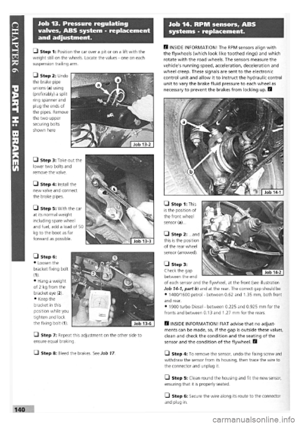
• Step 1: This
is the position of
the front wheel
sensor (a)...
• Step 2: ...and
this is the position
of the rear wheel
sensor (arrowed).
H INSIDE INFORMATION! FIAT advise that no adjust-
ments can be made, so, if the gap is outside these values,
clean and check the condition and the seating of the
sensor and the condition of the flywheel. D
L_l Step 4: To remove the sensor, undo the fixing screw and
withdraw the sensor from its housing, then trace the wire to
the connector and unplug it.
• Step 5: Clean round the housing and fit the new sensor,
ensuring that it is properly seated.
O Step 6: Secure the wire along its route to the connector
and plug in.
• Step 1: Position the car over a pit or on a lift with the
weight still on the wheels. Locate the valves
-
one on each
suspension trailing arm.
• Step 2: Undo
the brake pipe
unions (a) using
(preferably) a split
ring spanner and
plug the ends of
the pipes. Remove
the two upper
securing bolts
shown here
• Step 3: Take out the
lower two bolts and
remove the valve.
• Step 4: Install the
new valve and connect
the brake pipes.
• Step 5: With the car
at its normal weight
including spare wheel
and fuel, add a load of 50
kg to the boot as far
forward as possible.
• Step 6:
• Loosen the
bracket fixing bolt
(1).
• Hang a weight
of 2 kg from the
bracket eye (2).
• Keep the
bracket in this
position while you
tighten and lock
the fixing bolt (1).
Q Step 7: Repeat this adjustment on the other side to
ensure equal braking.
• Step 8: Bleed the brakes. See Job
17
• Step 3:
Check the gap
between the end
of each sensor and the flywheel, at the front (see illustration
Job
14-1,
part b) and at the rear. The correct gap should be:
• 1400/1600 petrol
-
between 0.62 and 1.35 mm, both front
and rear.
• 1900 turbo Diesel
-
between 0.225 and 0.925 mm for the
fronts and between 0.13 and 1.27 mm for the rears.
Page 137 of 171
Job 15. Flexible hoses -
replacement.
• Step 8: Bleed the brakes, see Job
17
H INSIDE INFORMATION: When disconnecting brake
pipes or hoses, it is helpful to minimise brake fluid loss.
This can be done by unscrewing the master cylinder
reservoir cap, laying a sheet of plastic across the
opening, and refitting the cap. This will prevent atmos-
pheric pressure from pushing the fluid out of opened
lines. D
/ • If a rigid pipe starts to
twist with the union, grip
the pipe as lightly as
possible, and see if you can stop it from turning.
• If not, cut through the pipe with a junior hacksaw
and replace the length of rigid pipe.
Job 16. Metal pipes -
replacement.
B INSIDE INFORMATION: When disconnecting brake
pipes or hoses, it is helpful to minimise brake fluid loss.
This can be done by unscrewing the master cylinder
reservoir cap, laying a sheet of plastic across the
opening, and refitting the cap. This will prevent atmos-
pheric pressure from pushing the fluid out of opened
lines. A pipe spanner makes the job much easier! B
Step 1: Undo the unions at each end of a pipe length.
Patience is often required because of the union seizing both in
its threads and on the pipe. See MAKING IT EASY! after Job
15,
Step 8 Use penetrating oil to help free seized unions, and
use a split-ring spanner rather than an open-ended one, to
reduce the risk of rounding off the union nuts.
• Step 2: Detach the pipe length from its securing clips and
remove it.
i^vj ens s * ^ step 3: where possible, use the old pipe as
a pattern to shape the new
one prior to fitting.
• Step 4: Follow the original route and secure the pipe in
the body clips.
Q Step 5: Connect the unions and bleed the system. See
Job
17
Job 17. Brake bleeding.
B INSIDE INFORMATION: Unless the master cylinder or
pressure regulating valve has been disturbed, it will only
be necessary to bleed the end of the braking system
which has been opened. If bleeding the whole system,
start bleeding at the left-hand rear brake. B
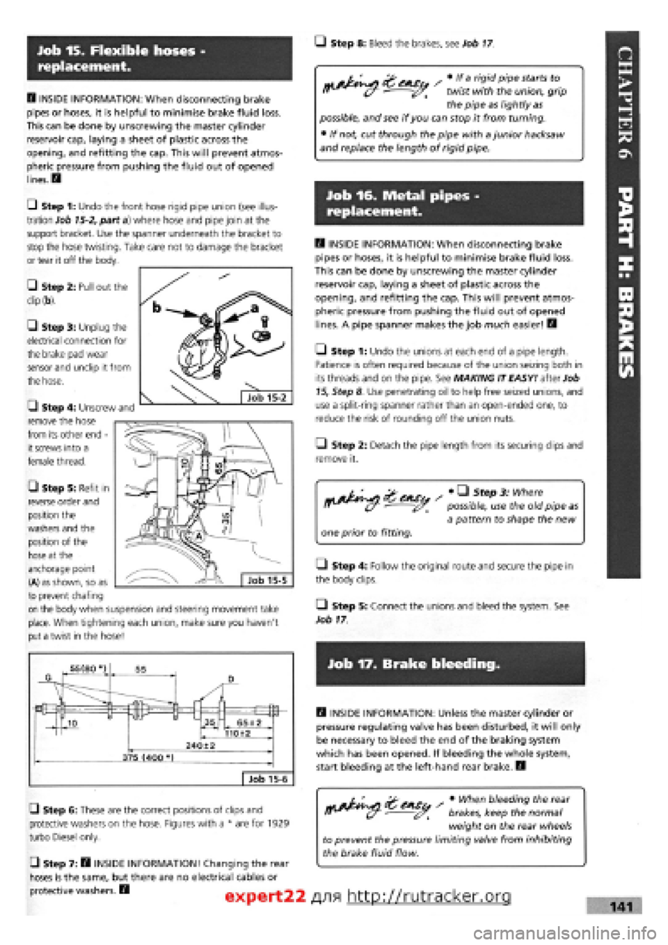
G Step 6: These are the correct positions of clips and
protective washers on the hose. Figures with a * are for 1929
turbo Diesel only.
• Step 7: B INSIDE INFORMATION! Changing the rear
hoses is the same, but there are no electrical cables or
protective washers. B
s • When bleeding the rear
brakes, keep the normal
weight on the rear wheels
to prevent the pressure limiting valve from inhibiting
the brake fluid flow.
expert22 f
\9\ http://rutracker.org 141
Ul Step 1: Undo the front hose rigid pipe union (see illus-
tration Job
15-2,
part a) where hose and pipe join at the
support bracket. Use the spanner underneath the bracket to
stop the hose twisting. Take care not to damage the bracket
or tear it off the body.
• Step 2: Pull out the
dip (b).
G Step 3: Unplug the
electrical connection for
the brake pad wear
sensor and unclip it from
the hose.
G Step 4: Unscrew and
remove the hose
from its other end -
it screws into a
female thread.
• Step 5: Refit in
reverse order and
position the
washers and the
position of the
hose at the
anchorage point
(A) as shown, so as
to prevent chafing
on the body when suspension and steering movement take
place. When tightening each union, make sure you haven't
put a twist in the hose!
Page 148 of 171
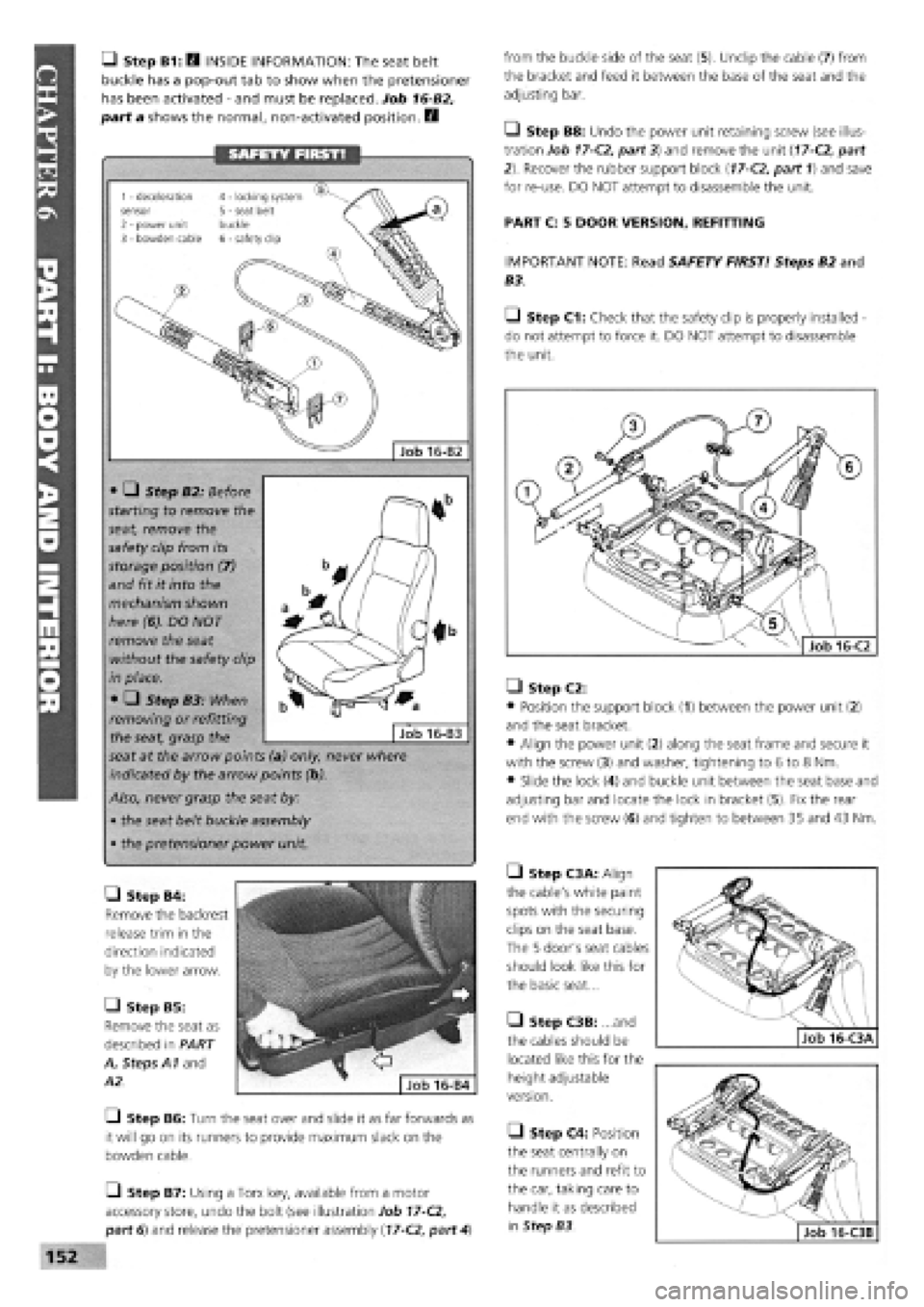
• Step B1: Q INSIDE INFORMATION: The seat belt
buckle has a pop-out tab to show when the pretensioner
has been activated
-
and must be replaced. Job 16-B2,
part a shows the normal, non-activated position. E3
from the buckle side of the seat (5). Unclip the cable (7) from
the bracket and feed it between the base of the seat and the
adjusting bar.
Q Step B8: Undo the power unit retaining screw (see illus-
tration Job
17-C2,
part 3) and remove the unit
(17-C2,
part
2). Recover the rubber support block
(17-C2,
part 1) and save
for re-use. DO NOT attempt to disassemble the unit.
PART C: 5 DOOR VERSION, REFITTING
IMPORTANT NOTE: Read SAFETY FIRST! Steps B2 and
B3.
Q Step C1: Check that the safety clip is properly installed -
do not attempt to force it. DO NOT attempt to disassemble
the unit.
• Step B4:
Remove the backrest
release trim in the
direction indicated
by the lower arrow.
• Step B5:
Remove the seat as
described in PART
A, Steps A1 and
A2.
—I Step B6: Turn the seat over and slide it as far forwards as
it will go on its runners to provide maximum slack on the
bowden cable.
O Step B7: Using a Torx key, available from a motor
accessory store, undo the bolt (see illustration Job
17-C2,
part 6) and release the pretensioner assembly
(17-C2,
part
4)
• Step C2:
• Position the support block (1) between the power unit (2)
and the seat bracket.
• Align the power unit (2) along the seat frame and secure it
with the screw (3) and washer, tightening to 6 to 8 Nm.
• Slide the lock (4) and buckle unit between the seat base and
adjusting bar and locate the lock in bracket (5). Fix the rear
end with the screw (6) and tighten to between 35 and 43 Nm.
• Step C3A: Align
the cable's white paint
spots with the securing
clips on the seat base.
The 5 door's seat cables
should look like this for
the basic seat...
• Step C3B: ...and
the cables should be
located like this for the
height adjustable
version.
• Step C4: Position
the seat centrally on
the runners and refit to
the car, taking care to
handle it as described
in Step B3.
SAFETY FIRST!
• • Step B2: Before
starting to remove the
seat, remove the
safety clip from its
storage position (7)
and fit it into the
mechanism shown
here (6). DO NOT
remove the seat
without the safety clip
in place.
• • Step B3: When
removing or refitting
the seat, grasp the
seat at the arrow points (a) only, never where
indicated by the arrow points (b).
Also, never grasp the seat by:
• the seat belt buckle assembly
• the pretensioner power unit.
Job 16-B3
• •
Job 16-B2
1 - deceleration sensor 2 - power unit 3 - bowden cable
4 - locking system 5 - seat belt buckle 6 - safety clip
Page 149 of 171
Job 17. Rear seat - removal and
refitting.
Job 16-D1
Q Step C5: Ensure that the seat operates smoothly and
withdraw the safety clip from its slot and position it on the
sensor frame cover. The unit is now operational.
PART D: 3 DOOR VERSION, REFITTING
IMPORTANT NOTE: Read SAFETY FIRST! Steps B2 and
B3.
• Step D2B: .. and
like this for height
adjustable version.
• Step D3: Now
follow Steps C4 and C5
to complete the job.
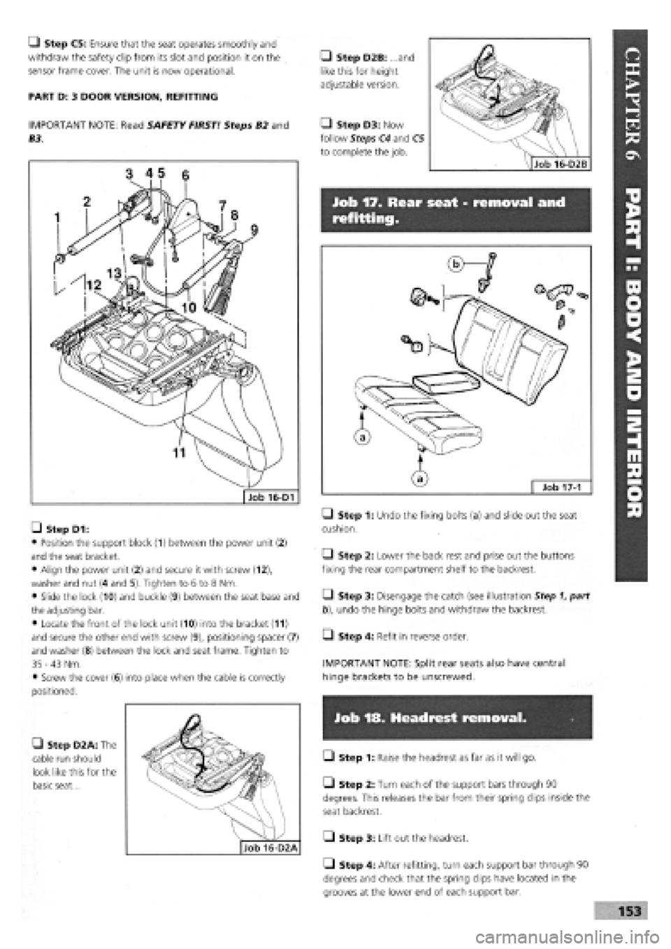
• Step D1:
• Position the support block (1) between the power unit (2)
and the seat bracket.
• Align the power unit (2) and secure it with screw (12),
washer and nut (4 and 5). Tighten to 6 to 8 Nm.
• Slide the lock (10) and buckle (9) between the seat base and
the adjusting bar.
• Locate the front of the lock unit (10) into the bracket (11)
and secure the other end with screw (9), positioning spacer (7)
and washer
(8)
between the lock and seat frame. Tighten to
35 -43
Nm.
• Screw the cover
(6)
into place when the cable is correctly
positioned.
• Step D2A: The
cable run should
look like this for the
basic seat...
• Step 1: Undo the fixing bolts (a) and slide out the seat
cushion.
Q Step 2: Lower the back rest and prise out the buttons
fixing the rear compartment shelf to the backrest.
• Step 3: Disengage the catch (see illustration Step 1, part
b), undo the hinge bolts and withdraw the backrest.
Q Step 4: Refit in reverse order.
IMPORTANT NOTE: Split rear seats also have central
hinge brackets to be unscrewed.
Job 18. Headrest removal.
• Step 1: Raise the headrest as far as it will go.
• Step 2: Turn each of the support bars through 90
degrees. This releases the bar from their spring clips inside the
seat backrest.
Q Step 3: Lift out the headrest.
Q Step 4: After refitting, turn each support bar through 90
degrees and check that the spring clips have located in the
grooves at the lower end of each support bar.
Page 151 of 171
IMPORTANT NOTE: Not all of the components listed here are fitted to all models.
CHAPTER 7
WIRING DIAGRAMS
IMPORTANT NOTE: Not all of the components listed here
are fitted to all models.
IMPORTANT NOTES:
3. We have sometimes shown the wiring diagram for a
'highest' spec, model, in the knowledge that 'lower'
spec, models are usually similar with the deletion of
certain components.
1. There are several hundred FIAT wiring diagrams for
the whole TIPO range. This is a representative selection,
covering the majority of applications. However, in the
event that your car's details are not covered here,
consult your nearest FIAT dealer.
2 All of the following are Tipo wiring diagrams. Tempra
saloons and estates are essentially similar.
4. 'EEC Stage 2 Engines' In late 1994, Tipo 1.4 and 2 -
Litre and Tempra 1.6 MPI vehicles were modified to suit
new emission regulations. These changes were NOT only
engine-related. Vehicles covered by this manual are Tipo
1.4 (with engine code no. 836A4.000) and Tempra 1.6
(with engine code 159B9.000). See Page 27 for location
of codes.
KEY:
1 Left front light cluster 2 Reversing light switch 3a Left horn 4 Electric cooling fan 5 Dual contact coolant thermal switch 6 Right longitudinal cable connection 7 Right front earth 8 Right front light cluster 9 Right horn 10 Screen/rear window washer pump 11 Left brake pad wear sensor 11A Right brake pad wear sensor 12 Ignition coil 12A Ignition coil with power module 12B Ignition coil with H.T. points 13 Digiplex electronic ignition control unit 13A Digiplex electronic ignition lead connection 13C Diagnostic socket for Digiplex electronic ignition 14 Left front earth 15 Battery earth 16 Engine coolant temperature sender unit 17 Battery 18 Ignition distributor 19 Sparkplug 20 Spark plug 21 Sparkplug 22 Spark plug 23 TDC sensor 24 Alternator 25 Oil pressure switch 26 Connector block 27 Brake fluid level sensor 28 Left side turn signal 30 Idle cut-out device 31 Starter motor 32 Throttle valve sensor 33 Pulse generator for speedometer signal 34 Windscreen wiper 35 Right side turn signal 36 P.T.C. resistor for heating fuel duct 37 Thermal switch for PTC 38 Vacuum sensor for vacuum gauge 39 Fuse and relay control unit E2 Turn signal and hazard warning light flasher E4 Fog light relay E5 Horn relay E6 Heated back window relay E7 Switch discharge connector E9 Windscreen wiper intermittent function E10 Rear fog light relay E11 Dipped beam relay E12 Main beam relay E13 Side light control relay E14 Central locking electronic control unit E1-E3-E8-E15-available (unused)
40 PTC resistor activation relay 41 20A fuse for inlet duct heater circuit 42 25A fuse for electric window ECU 43 Junction between facia cable and heater cable 44 Earth on left hand side of facia 45 Junction between facia cable and left front door
G Horn button H Windscreen wiper stalk I Back window wash/wipe selector L Heated rear windscreen switch M Rear screen wash/wipe switch N Windscreen wiper speed switch cables 56 Junction: facia cable and r.h. rear door cables Electric window control unit 57 Glove compartment light bulb Provision for left front speaker 58 Facia cable coupling with right front door cables Provision for left rear speaker 59 Facia cable coupling with right front door cables Supplementary earth point 60 Provision for right front speaker Instrument panel 60A Provision for right rear speaker A Direction indicators warning light 61 L.h. button for courtesy light and electric window B Side lights warning light 62 Junction between rear cable and left rear door C Main beam headlights warning light cables D Heated rear windscreen warning light 63 Junction between rear cable and left front door E Rear fog lights warning light cables E1 Fog lights warning light 64 Left front door lock motor and left front door F Hazard warning lights warning light open warning light G Battery recharging warning light 65 Left front electric window motor H Insufficient engine oil pressure warning light 66 Electric front window control buttons I Trip counter 67 Cigar lighter J Left brake lining wear warning light 68 Braking light switch J1 Seat belt undone warning light 69 Passenger compartment courtesy light K Handbrake on and low brake fluid level 69A Passenger compartment courtesy light with door warning light lock remote control receiver L Choke warning light 70 Hand brake warning light switch M ABS failure warning light 71 Passenger compartment ventilation fan switch N Instrument panel light bulbs 71A Passenger compartment ventilation control 0 Fuel level gauge 72 Passenger compartment ventilation fan speed P Coolant temperature gauge regulation resistor P1 Engine oil pressure gauge 73 Passenger compartment ventilation fan P2 Engine oil temperature gauge 74 Heater controls light bulbs Q Clock 75 Right front door lock motor and right front door R Heater plugs warning light open warning light S Speedometer 76 Right front electric window motor S1 Speed warning light 77 Right front electric window control button T Rev counter 78 R.h. button for courtesy lights and window U Trailer turn signal warning light 79 Luggage compartment lighting X Water in fuel filter warning light 80 Left rear earth Y Excessive turbocharging air pressure warning 80A Right rear earth light 81 Rear cable connection Y1 Lambda probe failure warning light 82 Left tail-light cluster Z Excessive automatic transmission fluid 83 Left rear door lock motor temperature warning light 84 Fuel level gauge Z1 Injection system failure warning light 85 Tailgate lock/release motor Ignition switch 86 Left number plate light Available for radio 87 Right number plate light Available for radio 88 Rear window wiper motor Hazard warning lights switch 89 Heated rear windscreen Stalk unit 90 Right tail-light cluster A Rear fog lights switch 91 Right rear door lock motor B Exterior lighting selector 92 Glow plug preheating system ECU c Control lighting bulb 93 Glow plugs D Light flasher button 94 Engine cooling fan first speed additional resistor E Turn signal stalk 95 30A fuse for engine cooling fan F Dipped/main beam headlight selector 96 Switch for automatic advance
155