sensor FIAT TEMPRA 1988 Service And User Guide
[x] Cancel search | Manufacturer: FIAT, Model Year: 1988, Model line: TEMPRA, Model: FIAT TEMPRA 1988Pages: 171, PDF Size: 18.05 MB
Page 64 of 171
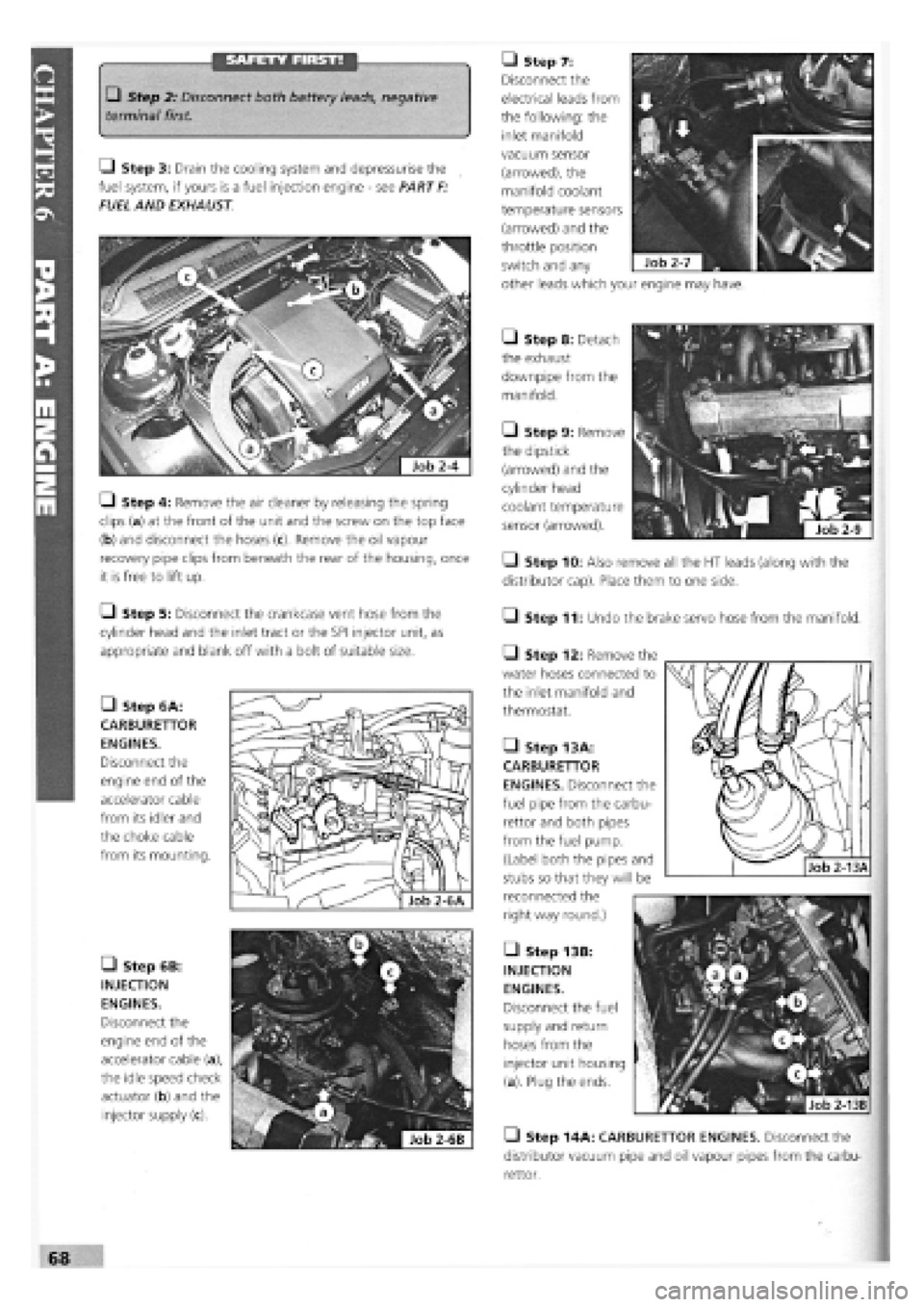
SAFETY FIRST! • Step 7:
Disconnect the
electrical leads from
the following: the
inlet manifold
• Step 2: Disconnect both battery leads, negative
terminal first.
Q Step 3: Drain the cooling system and depressurise the
fuel system, if yours is a fuel injection engine
-
see PART
F:
FUEL AND EXHAUST
• Step 6B:
INJECTION
ENGINES.
Disconnect the
engine end of the
accelerator cable (a),
the idle speed check
actuator (b) and the
injector supply (c).
• Step 8: Detach
the exhaust
downpipe from the
manifold.
• Step 9: Remove
the dipstick
(arrowed) and the
cylinder head
coolant temperature
sensor (arrowed).
• Step 10: Also remove all the HT leads (along with the
distributor cap). Place them to one side.
• Step 11: Undo the brake servo hose from the manifold.
Q Step 4: Remove the air cleaner by releasing the spring
clips (a) at the front of the unit and the screw on the top face
(b) and disconnect the hoses
recovery pipe clips from beneath the rear of the housing, once
it is free to lift up.
Q Step 5: Disconnect the crankcase vent hose from the
cylinder head and the inlet tract or the SPI injector unit, as
appropriate and blank off with a bolt of suitable size.
• Step 6A:
CARBURETTOR
ENGINES.
Disconnect the
engine end of the
accelerator cable
from its idler and
the choke cable
from its mounting.
Q Step 12: Remove the
water hoses connected to
the inlet manifold and
thermostat.
• Step 13 A:
CARBURETTOR
ENGINES. Disconnect the
fuel pipe from the carbu-
rettor and both pipes
from the fuel pump.
(Label both the pipes and
stubs so that they will be
reconnected the
right way round.)
• Step 13B:
INJECTION
ENGINES.
Disconnect the fuel
supply and return
hoses from the
injector unit housing
(a). Plug the ends.
• Step 14A: CARBURETTOR ENGINES. Disconnect the
distributor vacuum pipe and oil vapour pipes from the carbu-
rettor.
vacuum sensor
(arrowed), the
manifold coolant
temperature sensors
(arrowed) and the
throttle position
switch and any
other leads which your engine may have.
Page 65 of 171
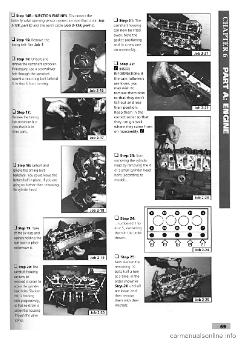
• Step 14B: INJECTION ENGINES. Disconnect the
butterfly valve opening sensor connection (see illustration Job
2-13B,
part b) and the earth cable (Job
2-13B,
part c).
Q Step 15: Remove the
timing belt. See Job 1.
• Step 16: Unbolt and
remove the camshaft sprocket.
If necessary, use a screwdriver
held
through the sprocket
against a mounting bolt behind
it,
to stop it from turning.
• Step 17:
Remove the timing
belt
tensioner but
note
that it is in
three parts.
• Step 18: Unbolt and
remove
the timing belt
backplate. You could leave the
bottom half in place, if you are
going no further than removing
the
cylinder head.
• Step 19: Take
off
the six
nuts and
washers
holding the
cam
cover in place
and
remove it.
• Step 20: The
camshaft housing
can
now be
removed in order to
access
the cylinder
head
bolts. Slacken
the
12
housing
bolts
progressively,
so that
no strain is
put on
the housing
through
the valve
springs.
Job
2-20
|
• Step 21: The
camshaft housing
can now be lifted
away. Note the
gasket positioning
and fit a new one
on reassembly.
• Step 22:
H INSIDE
INFORMATION: If
the cam followers
are loose, you
may wish to
remove them now
so that they don't
fall out and lose
their position.
Keep them in the
correct order so that
they can go back
where they came from
on reassembly. D
• Step 23: Start
removing the cylinder
head by removing the 4
or 5 small cylinder head
bolts (according to
model)...
^Hob^l]
• Step 24:
...numbered
1
to
4 or 5, slackening
them in the order
shown.
• Step 25:
Now slacken the
remaining 10
bolts half a turn
at a time, in the
order shown'in
Step 24, until all
are loose, and
then remove
them with their
washers.
ft ft ft ft tt
Job 2-24
Page 74 of 171
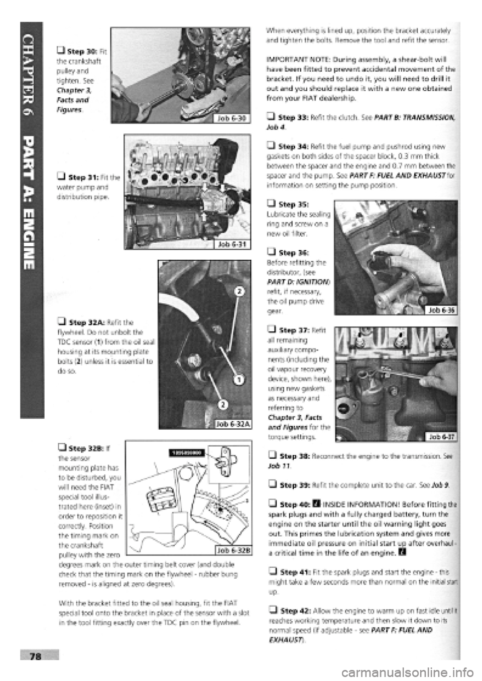
• Step 30: Fit
the crankshaft
pulley and
tighten. See
Chapter 3,
Facts and
Figures.
• Step 31: Fit the
water pump and
distribution pipe.
• Step 32A: Refit the
flywheel. Do not unbolt the
TDC sensor (1) from the oil seal
housing at its mounting plate
bolts
(2)
unless it is essential to
do so.
• Step 32B: If
the sensor
mounting plate has
to be disturbed, you
will need the FIAT
special tool illus-
trated here (inset) in
order to reposition it
correctly. Position
the timing mark on
the crankshaft
pulley with the zero
degrees mark on the outer timing belt cover (and double
check that the timing mark on the flywheel
-
rubber bung
removed
-
is aligned at zero degrees).
With the bracket fitted to the oil seal housing, fit the FIAT
special tool onto the bracket in place of the sensor with a slot
in the tool fitting exactly over the TDC pin on the flywheel.
When everything is lined up, position the bracket accurately
and tighten the bolts. Remove the tool and refit the sensor.
IMPORTANT NOTE: During assembly, a shear-bolt will
have been fitted to prevent accidental movement of the
bracket. If you need to undo it, you will need to drill it
out and you should replace it with a new one obtained
from your FIAT dealership.
• Step 33: Refit the clutch. See PARTB: TRANSMISSION,
Job 4.
Q Step 34: Refit the fuel pump and pushrod using new
gaskets on both sides of the spacer block, 0.3 mm thick
between the spacer and the engine and 0.7 mm between the
spacer and the pump. See PART F: FUEL AND EXHAUST for
information on setting the pump position.
• Step 35:
Lubricate the sealing
ring and screw on a
new oil filter.
• Step 36:
Before refitting the
distributor, (see
PART D: IGNITION)
refit, if necessary,
the oil pump drive
gear.
• Step 37: Refit
all remaining
auxiliary compo-
nents (including the
oil vapour recovery
device, shown here),
using new gaskets
as necessary and
referring to
Chapter
3,
Facts
and Figures for the
torque settings.
Q Step 38: Reconnect the engine to the transmission. See
Job 11.
Q Step 39: Refit the complete unit to the car. See Job
9.
• Step 40: fl INSIDE INFORMATION! Before fitting the
spark plugs and with a fully charged battery, turn the
engine on the starter until the oil warning light goes
out. This primes the lubrication system and gives more
immediate oil pressure on initial start up after overhaul-
a critical time in the life of an engine. B
• Step 41: Fit the spark plugs and start the engine
-
this
might take a few seconds more than normal on the initial start
up.
• Step 42: Allow the engine to warm up on fast idle
until
it
reaches working temperature and then slow it down to its
normal speed (if adjustable
-
see PART F: FUEL AND
EXHAUST)
Page 76 of 171
Job 8. Petrol engine/transmission
- removal.
IMPORTANT NOTE: See PARTB: TRANSMISSION for
gearbox removal by itself.
H INSIDE INFORMATION! The complete engine/trans-
mission unit is removed and replaced from under the car
- and this applies to all types. Make sure you can raise
the front of the car high enough (and support it safely
and securely!) to allow the power unit to be pulled clear
from underneath, before starting work! 13
• Step 1: Remove the bonnet
-
see PARTI: BODY AND
INTERIOR, Job 1.
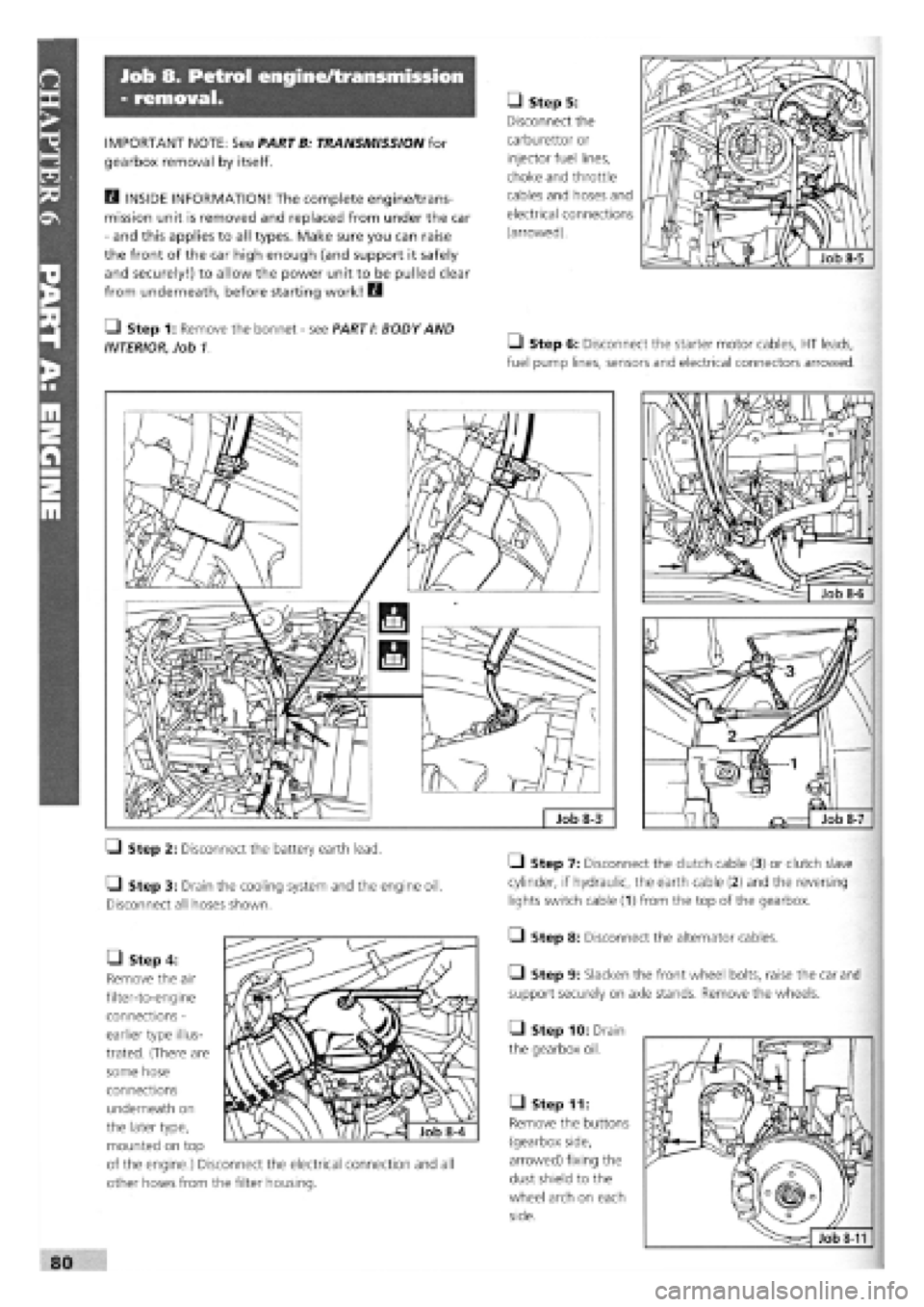
• Step 5:
Disconnect the
carburettor or
injector fuel lines,
choke and throttle
cables and hoses and
electrical connections
(arrowed).
Q Step 6: Disconnect the starter motor cables, HT leads,
fuel pump lines, sensors and electrical connectors arrowed.
Job
8-7
• Step 2: Disconnect the battery earth lead.
• Step 3: Drain the cooling system and the engine oil.
Disconnect all hoses shown.
• Step 7: Disconnect the clutch cable (3) or clutch slave
cylinder, if hydraulic, the earth cable (2) and the reversing
lights switch cable
(1)
from the top of the gearbox.
• Step 8: Disconnect the alternator cables.
Q Step 9: Slacken the front wheel bolts, raise the car and
support securely on axle stands. Remove the wheels.
• Step 10: Drain
the gearbox oil.
• Step 4:
Remove the air
filter-to-engine
connections
-
earlier type illus-
trated. (There are
some hose
connections
underneath on
the later type,
mounted on top
of the engine.) Disconnect the electrical connection and all
other hoses from the filter housing.
• Step 11:
Remove the buttons
(gearbox side,
arrowed) fixing the
dust shield to the
wheel arch on each
side.
Page 77 of 171
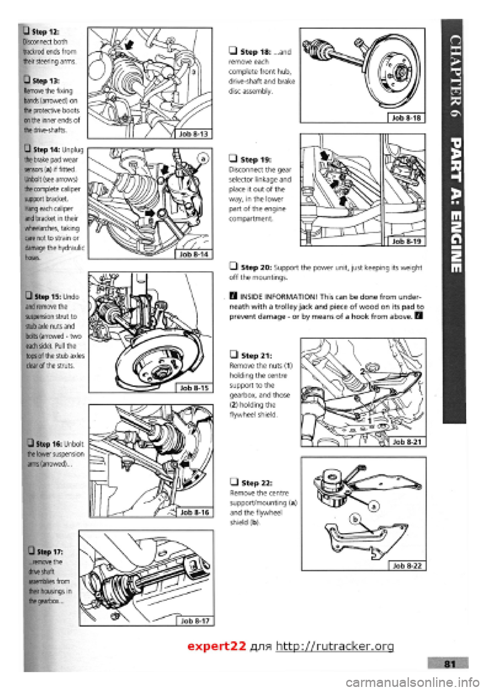
• Step 16: Unbolt
the
lower suspension
arms
(arrowed)...
• Step 17:
...remove
the
drive
shaft
assemblies
from
their housings in
the
gearbox...
• Step 15: Undo
and
remove the
suspension strut to
stub axle
nuts and
bolts
(arrowed
-
two
each side).
Pull the
tops
of the stub axles
clear
of the struts.
• Step 12:
Disconnect both
trackrod ends from
their
steering arms.
• Step 13:
Remove
the fixing
bands
(arrowed) on
the
protective boots
on the
inner ends of
the
drive-shafts.
• Step 14: Unplug
the brake
pad wear
sensors
(a) if fitted.
Unbolt (see arrows)
the
complete caliper
support bracket.
Hang
each caliper
and
bracket in their
wheelarches, taking
care
not to strain or
damage
the hydraulic
hoses.
• Step 21:
Remove the nuts (1)
holding the centre
support to the
gearbox, and those
(2) holding the
flywheel shield.
• Step 22:
Remove the centre
support/mounting (a)
and the flywheel
shield (b).
• Step 18: and
remove each
complete front hub,
drive-shaft and brake
disc assembly.
Job 8-18
Q Step 20: Support the power unit, just keeping its weight
off the mountings.
E3 INSIDE INFORMATION! This can be done from under-
neath with a trolley jack and piece of wood on its pad to
prevent damage
-
or by means of a hook from above. B
• Step 19:
Disconnect the gear
selector linkage and
place it out of the
way, in the lower
part of the engine
compartment.
Job 8-19
Job 8-13
expert22 fl/ia http://rutracker.org
I
Page 89 of 171
Job 17. Diesel engine.
Valve clearances - adjustment.
D INSIDE INFORMATION! After carrying out Job 16,
valve clearance measurement and adjustment is now
needed. Both measurement and shim replacement are
carried out in the same manner as for the petrol engine
(.Job
7), so refer to this and also to Chapter 3, Facts
and Figures for specifications. B
Job 18. Diesel engine - removal.
moving parts with engine oil during assembly. See Chapter 3,
Facts
and Figures for specified tightening torques.
luei suppiy diiu leium pipe;>
at the injection pump...
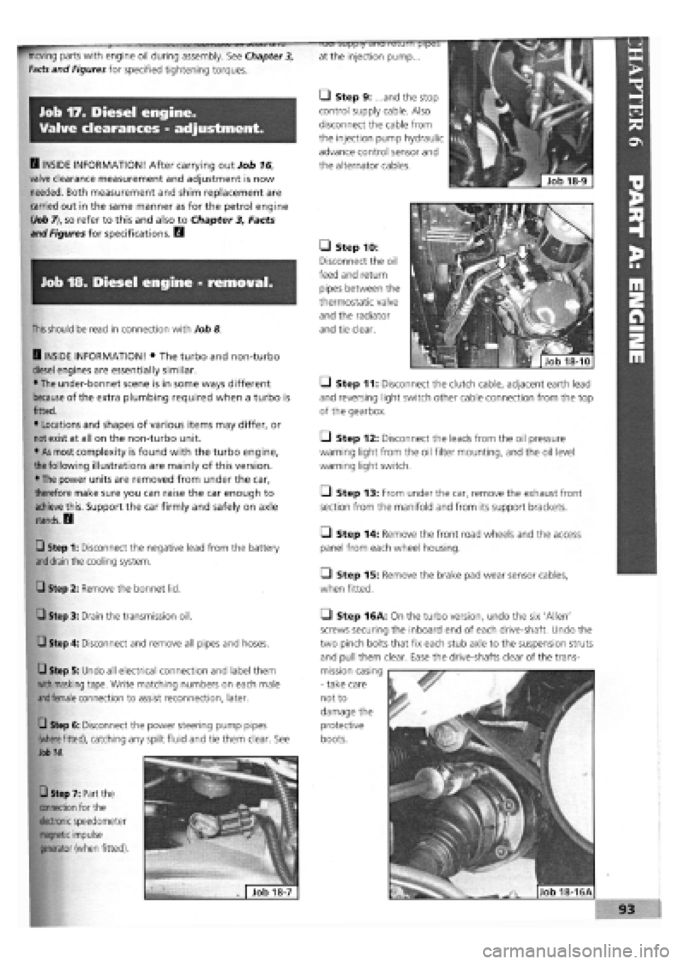
• Step 9: ...and the stop
control supply cable. Also
disconnect the cable from
the injection pump hydraulic
advance control sensor and
the alternator cables.
• Step 10:
Disconnect the oil
feed and return
pipes between the
thermostatic valve
and the radiator
and tie clear.
I
This should
be read in connection with Job 8
Q INSIDE INFORMATION! • The turbo and non-turbo
diesel engines are essentially similar.
• The under-bonnet scene is in some ways different
because of the extra plumbing required when a turbo is
fitted.
• Locations and shapes of various items may differ, or
not exist at all on the non-turbo unit.
• As most complexity is found with the turbo engine,
I
the
following illustrations are mainly of this version.
• The power units are removed from under the car,
therefore make sure you can raise the car enough to
achieve this. Support the car firmly and safely on axle
stands. D
Q Step 1: Disconnect the negative lead from the battery
and drain
the cooling system. Q Step 2: Remove the bonnet lid.
• Step 3: Drain the transmission oil.
Q Step 4: Disconnect and remove all pipes and hoses.
Q Step 5: Undo all electrical connection and label them
with masking
tape. Write matching numbers on each male
and female
connection to assist reconnection, later.
Q Step 6: Disconnect the power steering pump pipes
(where fitted),
catching any spilt fluid and tie them clear. See
Job 14.
• Step 7: Part the
connection for the
electronic
speedometer
magnetic impulse
generator
(when fitted).
Q Step 11: Disconnect the clutch cable, adjacent earth lead
and reversing light switch other cable connection from the top
of the gearbox.
• Step 12: Disconnect the leads from the oil pressure
warning light from the oil filter mounting, and the oil level
warning light switch.
• Step 13: From under the car, remove the exhaust front
section from the manifold and from its support brackets.
O Step 14: Remove the front road wheels and the access
panel from each wheel housing.
• Step 15: Remove the brake pad wear sensor cables,
when fitted.
Q Step 16A: On the turbo version, undo the six 'Allen'
screws securing the inboard end of each drive-shaft. Undo the
two pinch bolts that fix each stub axle to the suspension struts
and pull them clear. Ease the drive-shafts clear of the trans-
mission casing
-
take care
not to
damage the
protective
boots.
Page 91 of 171
Q Step 2: Before starting the engine, make sure all your
electrical connections are sound and your fuel, oil and coolant
connections are correct and secure.
Q Step 3: Run the engine to working temperature and then
allow to cool. Re-check all fluid levels.
Job 20. Diesel engine.
Mountings - replacement.
See
Job
12
and Job
18,
Step 20
Job 21. Diesel engine/
transmission (removed from car)
- separation.
Q Step 1: Remove the starter motor.
• Step 2: On the turbo version, undo the flange bolts see
Job
18,
Step 16A and withdraw the drive-shaft extension, if
still
fitted.
Q Step 3: Unbolt and remove the rear engine plate and the
gearbox, being careful to support the gearbox weight as it is
withdrawn.
Job 22. Diesel engine/
transmission (removed from car)
- reconnection.
Q Step 1: Before proceeding, check the condition of the
clutch and
its release mechanism. Make sure the driven plate
is
properly centred on the flywheel
-
see PART B: TRANS-
MISSION.
Q Step 2: Now reverse the order of separation, but be
careful when
engaging the gearbox input shaft with the
clutch
driven plate that you don't 'hang' its weight on the
splines.
Also,
see
Job 11.
Job 23. Diesel engine -
dismantling.
This Job should
be read in conjunction with Job 5 The
engines are
broadly similar although the information given in
this Job takes
priority for diesel engines. It is MOST
IMPORTANT that you read the FACT FILE on page 84.
SAFETY FIRST!
•
The inside
of diesel engines are particularly filthy
places!
•
Old diesel
oil
is
carcinogenic!
•
Wear suitable
impervious gloves!
I
• Step 1: Remove the timing belt and cylinder head. See
Jobs
13
and 14.
Q Step 2: Remove the alternator, water pump and
thermostat housing distribution pipe.
• Step 3: Remove the crankshaft timing belt sprocket.
Q INSIDE INFORMATION! Note that the bolt securing
the crankshaft sprocket has a left-hand thread and must
be undone clockwise. D
• Step 4: Unbolt the timing belt tensioner and idler pulleys.
• Step 5: Remove the injection pump sprocket.
Q INSIDE INFORMATION! You will need two FIAT tools
for this operation. One (No. 1860473000) is to prevent
the sprocket from turning when undoing the nut, and
the other (extractor No. 1842128000) to pull the sprocket
from the injection pump shaft. Alternatively it may be
possible to improvise a means of preventing sprocket
rotation, and a suitable three-leg puller may be carefully
used to withdraw the sprocket. Take care not to lose the
pump shaft Woodruff key. B
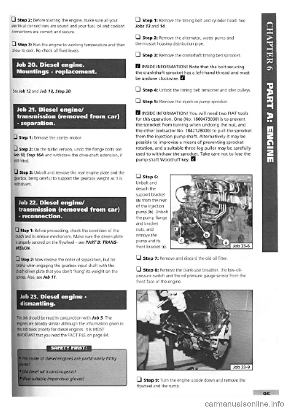
• Step 6:
Unbolt and
detach the
support bracket
(a) from the rear
of the injection
pump (b). Unbolt
the pump flange
and bracket
nuts, and
remove the
pump and its
front bracket (c).
• Step 7: Remove and discard the old oil filter.
Step 8: Remove the crankcase breather, the low-oil-
pressure switch and the oil pressure gauge sensor from the
front face of the engine.
• Step 9: Turn the engine upside down and remove the
flywheel and the sump.
Page 105 of 171
SAFETY FIRST!
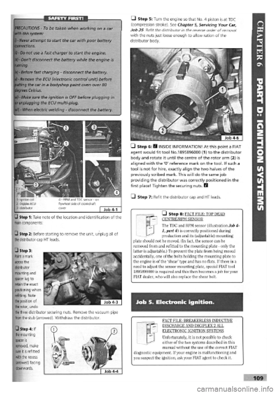
Step 1: Take note of the location and identification of the
main
components:
Q Step 2: Before starting to remove the unit, unplug all of
the
distributor cap
HT
leads.
M | The TDC and RPM sensor (illustration Job 4-
1, part 4) is correctly positioned during
production and its (adjustable) mounting
plate should not be moved. (In fact, the sensor can be
removed from and refitted to the mounting plate - only the
latter is adjustable.) To prevent the plate from being moved
accidentally, one of the bolts holding the mounting plate to
the engine is of the 'shear' type and has no flats. If there is a
need to adjust the sensor mounting plate, special FIAT tool
1895898000 is required and this then becomes a job for your
FIAT dealer, who will also replace the shear bolt.
• Step 8: FACT FILE: TOP DEAD
CENTRE/RPM SENSOR
PRECAUTIONS -
To be taken when working on a car
with this system:
i) - Never
attempt to start the car with poor battery
connections.
ii) - Do
not use a fast charger to start the engine.
iii) -
Don't disconnect the battery while the engine is
running.
iv) -
Before fast charging
-
disconnect the battery.
vj - Remove
the ECU (electronic control unit) before
putting
the car in a bodyshop paint oven over
80
degrees Celsius.
vi) -
Make sure the ignition is OFF before plugging in
or unplugging
the ECU multi-plug.
vii) -
When electric welding
-
disconnect the battery.
Q Step 5: Turn the engine so that No. 4 piston is at TDC
(compression stroke). See Chapter
5,
Servicing Your Car,
Job 25 Refit the distributor in the reverse order of removal1
with the nuts just loose enough to allow ration of the
distributor body.
• Step 6: E3 INSIDE INFORMATION! At this point a FIAT
agent would fit tool No.1895896000 (1) to the distributor
body and rotate it until the centre of the rotor arm (2) is
aligned with the '0' reference mark on the tool. If such a
tool is not for hire, exactly align the two halves of the
previously scribed mark. This will do the same job
providing the distributor was correctly positioned in the
first place! Tighten the securing nuts. Q
• Step 7: Refit the distributor cap and HT leads.
Job S. Electronic ignition.
FACT FILE: BREAKERLESS INDUCTIVE
DISCHARGE AND DIGIPLEX 2 ALL
ELECTRONIC IGNITION SYSTEMS
Unfortunately, it is not possible to check
either of the two systems described in this
manual without the use of the correct FIAT
diagnostic equipment. If your engine is malfunctioning and
you suspect the ignition, ask your FIAT agent to check it.
109
• Step 3:
Paint a
mark
across
the
distributor
mounting and
spacer lug
to
retain
the exact
positioning when
refitting. Note
the position
of
the rotor,
undo
the three
distributor securing nuts. Remove the vacuum pipe
from the
stub (arrowed). Withdraw the distributor.
• Step 4: If
the
mounting
spacer
is
removed, make
sure
it
is
refitted
with the
recess
(arrowed) facing
downwards.
Page 112 of 171
PART F: FUEL AMD EXHAUST SYSTEMS
PART F: Contents
Job 1. Fuel system types. Job 9. Electric fuel pump, petrol engine (S.P.I.)
-
Job 2. Carburettor
-
removal and refitting. replacement.
Job 3. Petrol injection unit
-
removal and refitting. Job 10. Fuel tank
-
removal and refitting.
Job 4. Accelerator cable, carburettor engines
-
replacement Job 11. Hot air hoses/thermo-valves
-
general.
and adjustment. Job 12. Lambda sensor (S.P.I, engines)
-
replacement.
Job 5. Carburettor choke cable
-
replacement and Job 13. Fuel evaporation system.
adjustment. Job 14. Exhaust system
-
replacement.
Job 6. Accelerator cable, petrol injection engines -Job 15. Turbocharger, diesel engine
-
replacement.
replacement and adjustment. Job 16. Diesel injection pump
-
removal and refitting.
Job 7. Diesel engines. Accelerator cable
-
replacement and Job 17. Diesel injectors
-
remove and refit.
adjustment. Job 18. Bleeding Diesel fuel system.
Job 8. Mechanical fuel pump, petrol engine (carburettored) -
replacement.
Job 1. Fuel system types.
FACT FILE: FUEL INJECTION/ELECTRONIC
IGNITION PRECAUTIONS
OBSERVE THE FOLLOWING PRECAUTIONS
WHEN WORKING ON PETROL-ENGINED
VEHICLES WITH FUEL INJECTION - ELECTRONIC
IGNITION SYSTEMS:
• never start the engine when the electrical terminals are
poorly connected or loose on the battery poles;
• never use a quick battery charger to start the engine;
• never disconnect the battery from the car circuit with the
engine running;
• when charging the battery quickly, first disconnect the
battery from the vehicle circuit;
• if the vehicle is placed in a bodyshop drying oven after
painting at a temperature of more than 80 degrees Celsius,
first remove the injection/ignition ECU;
• never connect or disconnect the ECU multiple connector
with the ignition key in MARCIA position;
• always disconnect battery negative lead before carrying out
electrical welding on vehicle.
Note that some systems contain one memory that is always
active (stand-by memory) and that stores learnt self-adaptive
values. Because this data is lost when the battery is discon-
nected, this operation should be carried out as infrequently as
possible.
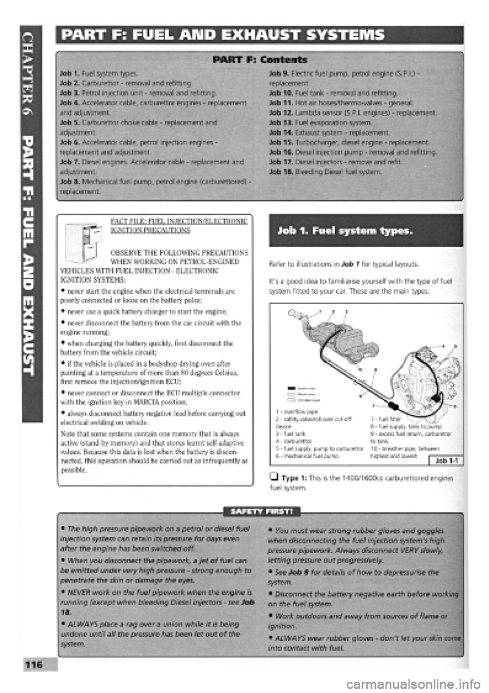
Refer to illustrations in Job 1 for typical layouts.
It's a good idea to familiarise yourself with the type of fuel
system fitted to your car. These are the main types.
• Type 1: This is the 1400/1600cc carburettored engines
fuel system.
SAFETY FIRST!
• The high pressure pipework on a petrol or diesel fuel
injection system can retain its pressure for days even
after the engine has been switched off.
• When you disconnect the pipework, a jet of fuel can
be emitted under very high pressure
-
strong enough to
penetrate the skin or damage the eyes.
• NEVER work on the fuel pipework when the engine is
running (except when bleeding Diesel injectors
-
see Job
18.
• ALWAYS place a rag over a union while it is being
undone until all the pressure has been let out of the
system.
• You must wear strong rubber gloves and goggles
when disconnecting the fuel injection system's high
pressure pipework. Always disconnect VERY slowly,
letting pressure out progressively.
• See Job 8 for details of how to depressurise the
system.
• Disconnect the battery negative earth before working
on the fuel system.
• Work outdoors and away from sources of flame or
ignition.
• ALWAYS wear rubber gloves
-
don't let your skin come
into contact with fuel.
1 - overflow pipe 2 - safety valve/roll over cut-off device 3 - fuel tank 4 - carburettor 5 - fuel supply, pump to carburettor 6 - mechanical fuel pump
7 - fuel filter 8 - fuel supply, tank to pump 9 - excess fuel return, carburettor to tank 10 - breather pipe, between highest and lowest Job
1-1
Page 114 of 171
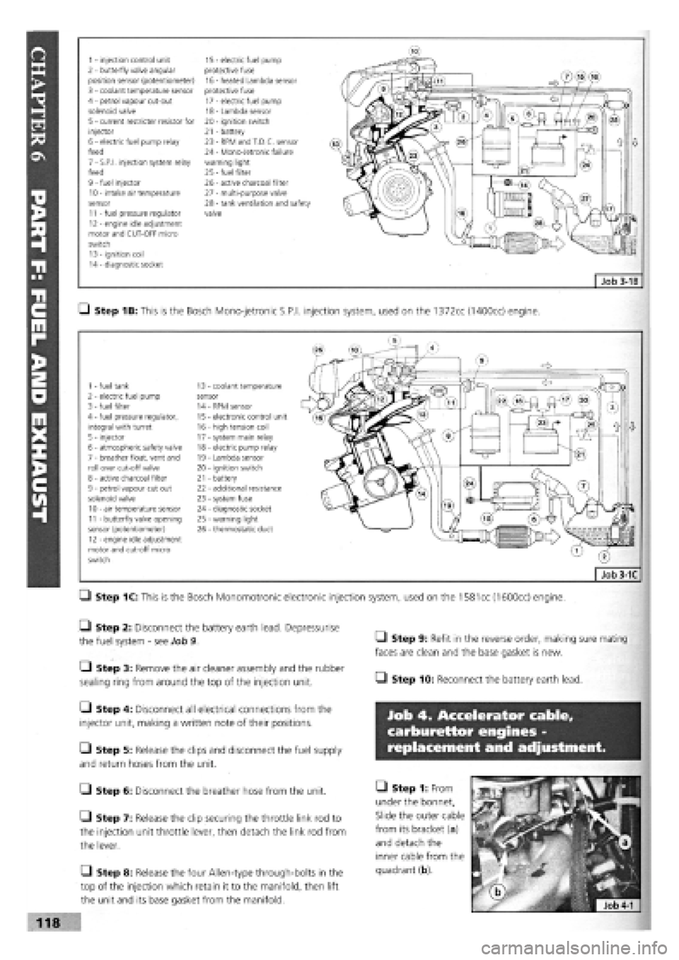
1 - injection control unit 15 - electric fuel pump 2 - butterfly valve angular protective fuse position sensor (potentiometer) 16 - heated Lambda sensor 3 - coolant temperature sensor protective fuse 4 - petrol vapour cut-out 17 - electric fuel pump solenoid valve 18 - Lambda sensor 5 - current restricter resistor for 20 - ignition switch injector 21 - battery 6 - electric fuel pump relay 23 - RPM and T.D.C. sensor feed 24 - Mono-Jetronic failure 7 - S.P.I, injection system relay warning light feed 25
-
fuel filter 9 - fuel injector 26 - active charcoal filter 10 - intake air temperature 27 - multi-purpose valve sensor 28 - tank ventilation and safety 11 - fuel pressure regulator valve 12 - engine idle adjustment motor and CUT-OFF micro switch 13 - ignition coil 14 - diagnostic socket
Q Step 1B: This is the Bosch Mono-jetronic S.P.I, injection system, used on the 1372cc (1400cc) engine.
1 - fuel tank 13 coolant temperature 2 - electric fuel pump sensor 3 - fuel filter 14 RPM sensor 4 - fuel pressure regulator, 15 electronic control unit integral with turret 16 - high tension coil 5 - injector 17 - system main relay 6 - atmospheric safety valve 18 - electric pump relay 7 - breather float, vent and 19 - Lambda sensor roll over cut-off valve 20 - ignition switch 8 - active charcoal filter 21 - battery 9 - petrol vapour cut out 22 - additional resistance solenoid valve 23 - system fuse 10 - air temperature sensor 24 - diagnostic socket 11 - butterfly valve opening 25 - warning light sensor (potentiometer) 26 - thermostatic duct 12 - engine idle adjustment motor and cut-off micro switch
Q Step 1C: This is the Bosch Monomotronic electronic injection system, used on the
1581
cc (1600cc) engine.
• Step 2: Disconnect the battery earth lead. Depressurise
the fuel system
-
see Job 9.
• Step 3: Remove the air cleaner assembly and the rubber
sealing ring from around the top of the injection unit.
Q Step 4: Disconnect all electrical connections from the
injector unit, making a written note of their positions.
Q Step 5: Release the clips and disconnect the fuel supply
and return hoses from the unit.
G Step 6: Disconnect the breather hose from the unit.
• Step 7: Release the clip securing the throttle link rod to
the injection unit throttle lever, then detach the link rod from
the lever.
Q Step 8: Release the four Allen-type through-bolts in the
top of the injection which retain it to the manifold, then lift
the unit and its base gasket from the manifold.
• Step 9: Refit in the reverse order, making sure mating
faces are clean and the base gasket is new.
• Step 10: Reconnect the battery earth lead.
Job 4. Accelerator cable,
carburettor engines -
replacement and adjustment.
• Step 1: From
under the bonnet,
Slide the outer cable
from its bracket (a)
and detach the
inner cable from the
quadrant (b).
118