cooling FIAT TEMPRA 1988 Service And Repair Manual
[x] Cancel search | Manufacturer: FIAT, Model Year: 1988, Model line: TEMPRA, Model: FIAT TEMPRA 1988Pages: 171, PDF Size: 18.05 MB
Page 1 of 171
Please be sure to read the whole of this Chapter before carrying out any work on your car.
SAFETY FIRST!
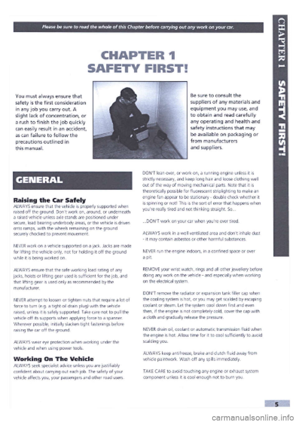
You must always ensure that
safety is the first consideration
in any job you carry out. A
slight lack of concentration, or
a rush to finish the job quickly
can easily result in an accident,
as can failure to follow the
precautions outlined in
this manual.
Be sure to consult the
suppliers of any materials and
equipment you may use, and
to obtain and read carefully
any operating and health and
safety instructions that may
be available on packaging or
from manufacturers
and suppliers.
Raising the Car Safely
ALWAYS ensure that the vehicle is properly supported when
raised off the ground. Don't work on, around, or underneath
a raised vehicle unless axle stands are positioned under
secure, load bearing underbody areas, or the vehicle is driven
onto ramps, with the wheels remaining on the ground
securely chocked to prevent movement.
NEVER work on a vehicle supported on a jack. Jacks are made
for lifting the vehicle only, not for holding it off the ground
while it is being worked on.
ALWAYS ensure that the safe working load rating of any
jacks, hoists or lifting gear used is sufficient for the job, and
that lifting gear is used only as recommended by the
manufacturer.
NEVER attempt to loosen or tighten nuts that require a lot of
force to turn (e.g. a tight oil drain plug) with the vehicle
raised, unless it is safely supported. Take care not to pull the
vehicle off its supports when applying force to a spanner.
Wherever possible, initially slacken tight fastenings before
raising the car off the ground.
ALWAYS wear eye protection when working under the
vehicle and when using power tools.
Working On The Vehicle
ALWAYS seek specialist advice unless you are justifiably
confident about carrying out each job. The safety of your
vehicle affects you, your passengers and other road users.
DON'T lean over, or work on, a running engine unless it is
strictly necessary, and keep long hair and loose clothing well
out of the way of moving mechanical parts. Note that it is
theoretically possible for fluorescent striplighting to make an
engine fan appear to be stationary
-
double check whether it
is spinning or not! This is the sort of error that happens when
you're really tired and not thinking straight. So...
...DON'T work on your car when you're over tired.
ALWAYS work in a well ventilated area and don't inhale dust
- it may contain asbestos or other harmful substances.
NEVER run the engine indoors, in a confined space or over
a pit.
REMOVE your wrist watch, rings and all other jewellery before
doing any work on the vehicle
-
and especially when working
on the electrical system.
DON'T remove the radiator or expansion tank filler cap when
the cooling system is hot, or you may get scalded by escaping
coolant or steam. Let the system cool down first and even
then, if the engine is not completely cold, cover the cap with
a cloth and gradually release the pressure.
NEVER drain oil, coolant or automatic transmission fluid when
the engine is hot. Allow time for it to cool sufficiently to avoid
scalding you.
ALWAYS keep antifreeze, brake and clutch fluid away from
vehicle paintwork. Wash off any spills immediately.
TAKE CARE to avoid touching any engine or exhaust system
component unless it is cool enough not to burn you.
Page 3 of 171
Mains Electricity
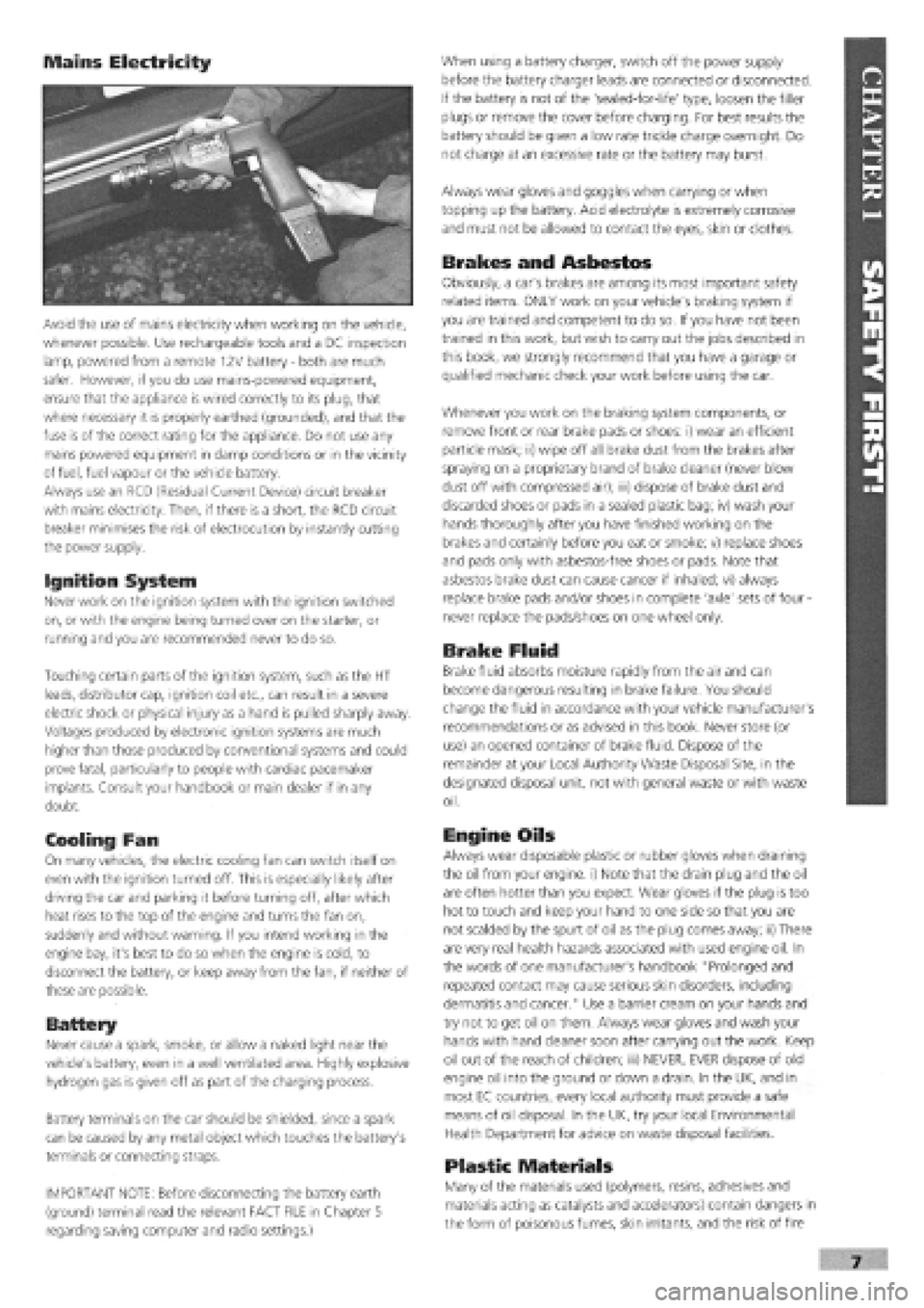
Avoid the use of mains electricity when working on the vehicle,
whenever possible. Use rechargeable tools and a DC inspection
lamp, powered from a remote 12V battery
-
both are much
safer. However, if you do use mains-powered equipment,
ensure that the appliance is wired correctly to its plug, that
where necessary it is properly earthed (grounded), and that the
fuse is of the correct rating for the appliance. Do not use any
mains powered equipment in damp conditions or in the vicinity
of fuel, fuel vapour or the vehicle battery.
Always use an RCD (Residual Current Device) circuit breaker
with mains electricity. Then, if there is a short, the RCD circuit
breaker minimises the risk of electrocution by instantly cutting
the power supply.
Ignition System
Never work on the ignition system with the ignition switched
on, or with the engine being turned over on the starter, or
running and you are recommended never to do so.
Touching certain parts of the ignition system, such as the HT
leads, distributor cap, ignition coil etc., can result in a severe
electric shock or physical injury as a hand is pulled sharply away.
Voltages produced by electronic ignition systems are much
higher than those produced by conventional systems and could
prove fatal, particularly to people with cardiac pacemaker
implants. Consult your handbook or main dealer if in any
doubt.
Cooling Fan
On many vehicles, the electric cooling fan can switch itself on
even with the ignition turned off. This is especially likely after
driving the car and parking it before turning off, after which
heat rises to the top of the engine and turns the fan on,
suddenly and without warning. If you intend working in the
engine bay, it's best to do so when the engine is cold, to
disconnect the battery, or keep away from the fan, if neither of
these are possible.
Battery
Never cause a spark, smoke, or allow a naked light near the
vehicle's battery, even in a well ventilated area. Highly explosive
hydrogen gas is given off as part of the charging process.
Battery terminals on the car should be shielded, since a spark
can be caused by any metal object which touches the battery's
terminals or connecting straps.
IMPORTANT NOTE: Before disconnecting the battery earth
(ground) terminal read the relevant FACT FILE in Chapter 5
regarding saving computer and radio settings.)
When using a battery charger, switch off the power supply
before the battery charger leads are connected or disconnected.
If the battery is not of the 'sealed-for-life' type, loosen the filler
plugs or remove the cover before charging. For best results the
battery should be given a low rate trickle charge overnight. Do
not charge at an excessive rate or the battery may burst.
Always wear gloves and goggles when carrying or when
topping up the battery. Acid electrolyte is extremely corrosive
and must not be allowed to contact the eyes, skin or clothes.
Brakes and Asbestos
Obviously, a car's brakes are among its most important safety
related items. ONLY work on your vehicle's braking system if
you are trained and competent to do so. If you have not been
trained in this work, but wish to carry out the jobs described in
this book, we strongly recommend that you have a garage or
qualified mechanic check your work before using the car.
Whenever you work on the braking system components, or
remove front or rear brake pads or shoes: i) wear an efficient
particle mask; ii) wipe off all brake dust from the brakes after
spraying on a proprietary brand of brake cleaner (never blow
dust off with compressed air); iii) dispose of brake dust and
discarded shoes or pads in a sealed plastic bag; iv) wash your
hands thoroughly after you have finished working on the
brakes and certainly before you eat or smoke; v) replace shoes
and pads only with asbestos-free shoes or pads. Note that
asbestos brake dust can cause cancer if inhaled; vi) always
replace brake pads and/or shoes in complete 'axle' sets of four
-
never replace the pads/shoes on one wheel only.
Brake Fluid
Brake fluid absorbs moisture rapidly from the air and can
become dangerous resulting in brake failure. You should
change the fluid in accordance with your vehicle manufacturer's
recommendations or as advised in this book. Never store (or
use) an opened container of brake fluid. Dispose of the
remainder at your Local Authority Waste Disposal Site, in the
designated disposal unit, not with general waste or with waste
oil.
Engine Oils
Always wear disposable plastic or rubber gloves when draining
the oil from your engine, i) Note that the drain plug and the oil
are often hotter than you expect. Wear gloves if the plug is too
hot to touch and keep your hand to one side so that you are
not scalded by the spurt of oil as the plug comes away; ii) There
are very real health hazards associated with used engine oil. In
the words of one manufacturer's handbook "Prolonged and
repeated contact may cause serious skin disorders, including
dermatitis and cancer." Use a barrier cream on your hands and
try not to get oil on them. Always wear gloves and wash your
hands with hand cleaner soon after carrying out the work. Keep
oil out of the reach of children; iii) NEVER, EVER dispose of old
engine oil into the ground or down a drain. In the UK, and in
most EC countries, every local authority must provide a safe
means of oil disposal. In the UK, try your local Environmental
Health Department for advice on waste disposal facilities.
Plastic Materials
Many of the materials used (polymers, resins, adhesives and
materials acting as catalysts and accelerators) contain dangers in
the form of poisonous fumes, skin irritants, and the risk of fire
Page 8 of 171
AIR CONDITIONING (EARLY MODELS)
Air conditioning is an optional extra fitted to some
models of Tipo and Tempra.
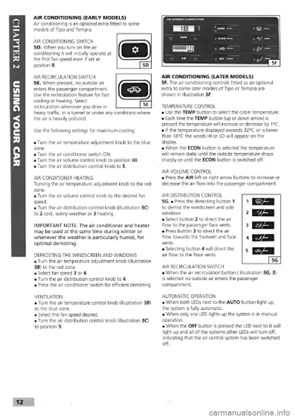
AIR CONDITIONING SWITCH
5D. When you turn on the air
conditioning it will initially operate at
the first fan speed even if set at
position 0.
AIR RECIRCULATION SWITCH
5E. When pressed, no outside air
enters the passenger compartment.
Use the recirculation feature for fast
cooling or heating. Select
recirculation whenever you drive in
heavy traffic, in a tunnel or under any conditions where
the air is heavily polluted.
Use the following settings for maximum cooling:
• Turn the air temperature adjustment knob to the blue
zone.
• Turn the air conditioner switch ON.
• Turn the air volume control knob to position Mil.
• Turn the air distribution control knob to 5.
AIR CONDITIONER HEATING
Turning the air temperature adjustment knob to the red
zone:
• Turn the air volume control knob to the desired fan
speed.
• Turn the air distribution control knob (illustration 50
to 2 cold, sunny weather or 3 heating.
IMPORTANT NOTE: The air conditioner and heater
may be used at the same time during winter or
whenever the weather is particularly humid, for
optimal demisting .
DEFROSTING THE WINDSCREEN AND WINDOWS
• Turn the air temperature adjustment knob (illustration
56) to the red zone.
• Select fan speed 3 or 4.
• Turn the air distribution control knob to 4.
• Press the air conditioner switch for efficient demisting.
VENTILATION
• Turn the air temperature control knob (illustration SB)
to the blue zone.
• Select the fan speed desired.
• Turn the air distribution control knob (illustration 50
to position 5.
AIR CONDITIONING (LATER MODELS)
5F. The air conditioning controls fitted as an optional
extra to some later models of Tipo or Tempra are
shown in illustration 5F
TEMPERATURE CONTROL
• Use the TEMP button to select the cabin temperature.
• Each time the TEMP button (up or down arrow) is
pressed the temperature will increase or decrease by 1°C.
• If the temperature displayed exceeds 32°C or is lower
than 18°C the words HI or LO will appear on the
display.
• When the ECON button is selected the temperature
will remain static until the outside temperature drops
sharply or until the ECON button is switched off.
AIR VOLUME CONTROL
• Press the AIR left or right arrow buttons to increase or
decrease the air flow into the passenger compartment.
AIR DISTRIBUTION CONTROL
5G. • Press the demisting button 1
to demist the windscreen and side
windows.
• Select button 2 to direct the air
flow to the passenger face vents.
• Press button 3 to direct the air
flow towards the footwell and face
vents.
• Selecting button 4 will direct the
air flow to the floor vents.
AIR RECIRCULATION SWITCH
• When the air recirculation button (illustration 5G, 5)
is selected no outside air enters the passenger
compartment.
AUTOMATIC OPERATION
• When both LEDs next to the AUTO button light up,
the system is fully automatic.
• When only one LED lights up the system is in manual
operation.
• When the OFF button is pressed the LED next to it will
light up and all of the systems other LEDs will turn off,
indicating that the air control system has been switched
off.
vh
5G
Page 17 of 171
1372 OHC 1580/1581 OHC 1697 Diesel 1929 D 1929 Turbo D
CRANKSHAFT END FLOAT:
0.055-0.265 0.055-0.265
Engine 'top end' and valve gear
CAMSHAFT BEARING OUTER DIAMETERS
(1
= Front)
1: 29.989-30.014
2: 47.98-48.005
48.180-48.205
48.38-48.405
48.58-48.605
CAM FOLLOWER DIAMETER:
36.975-36.995
CAM FOLLOWER BORE CLEARANCE:
0.005-0.05
INLET VALVE HEAD SIZE:
37.35-37.65
EXHAUST VALVE HEAD SIZE:
30.85-31.15
29.989-30.014
47.98-48.005
48.180-48.205
48.38-48.405
48.58-48.605
36.975-36.995
0.005-0.05
A: 37.35-37.65
B: 39.2-39.7
A: 32.85-33.45
B: 30.85-31.15
0.055-0.305
42.02-43.04
25-545-25.57
24.045-24.07
43.02-43.04
N/A
36.975-36.995
0.005-0.05
37.3-37.6
33.3-33.6
VALVE SEAT RE-CUTTING ANGLE:
45 degrees, +/-5' 45 degrees, +/-5' 45 degrees, +/-5'
VALVE FACE RE-CUTTING ANGLE:
45 degrees 30' +/-5' 45 degrees 30' +/-5' 45 degrees 30' +/-7'
VALVE SHIM THICKNESSES: Between 3.25 and 4.7 mm in shim increments of 0.05 mm
1:35.593-35.618 1:35.593-35.618 N/A
2:31.940-39.960 2:31.940-39.960
PRECHAMBER PROTRUSION BEYOND CYLINDER HEAD (arrowed):
N/A N/A -0.765-0.055
0.055-0.305
43.02-43.04
25.545-25.57
24.045-24.07
43.02-43.04
N/A
36.975-36.995
0.005-0.05
37.3-37.6
33.3-33.6
45 degrees, +/-5'
45 degrees 30' +/-7'
N/A
-0.765-0.055
0.055-0.305
43.02-43.04
25.545-25.57
24.045-24.07
43.02-43.04
N/A
36.975-36.995
0.005-0.5
37.3-37.6
33.3-33.6
45 degrees, +/-5'
45 degrees 30' +1-1'
N/A
-0.765-0.055
Cooling system
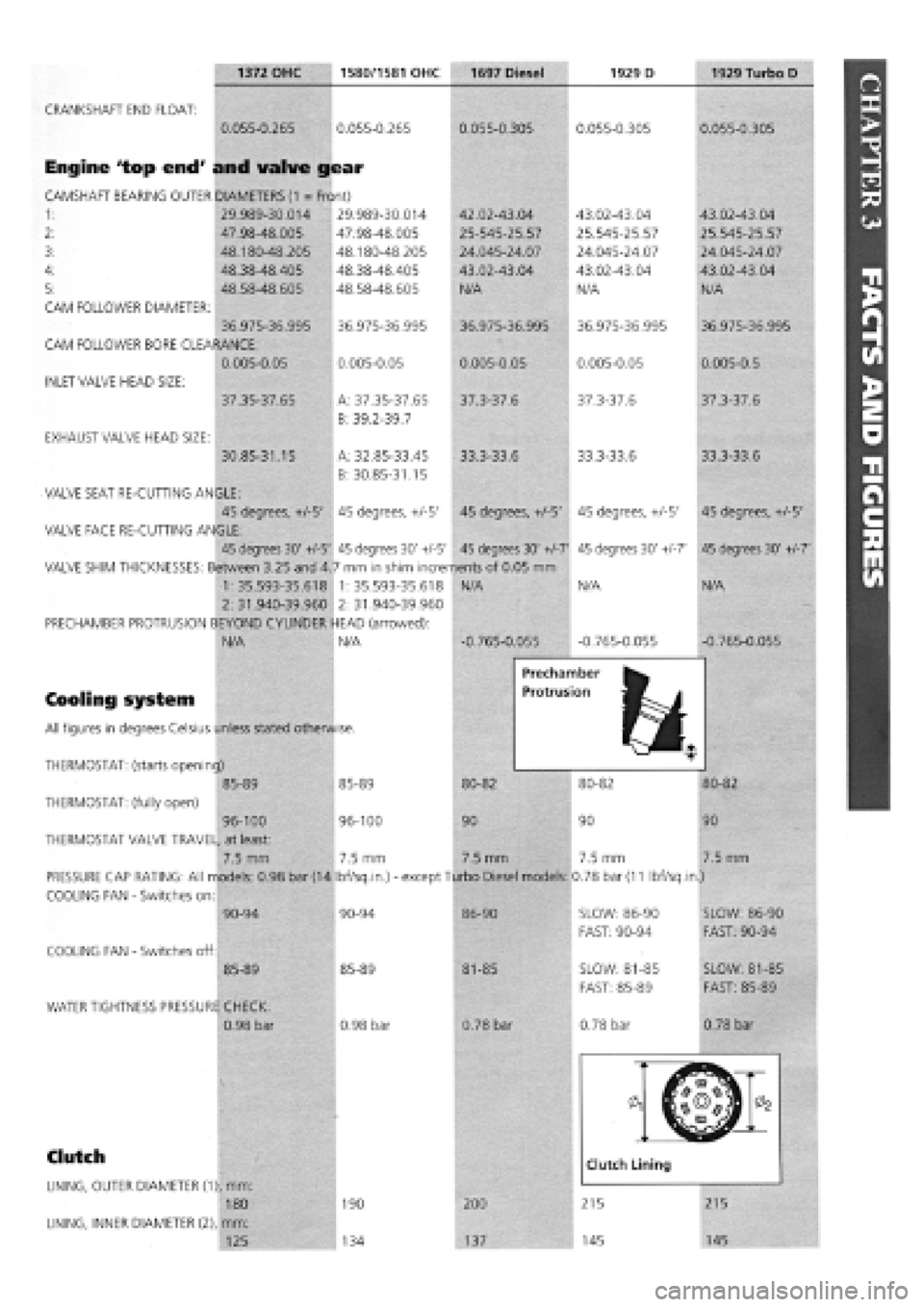
All figures in degrees Celsius unless stated otherwise.
Prechamber
Protrusion
THERMOSTAT: (starts opening) M^M
85-89 85-89 80-82 80-82
THERMOSTAT: (fully open)
96-100 96-100 90 90
THERMOSTAT VALVE TRAVEL, at least:
7.5 mm 7.5 mm 7.5 mm 7.5 mm
PRESSURE CAP RATING: All models: 0.98 bar (14 Ibf/sq.in.)
-
except Turbo Diesel models: 0.78 bar
(11
Ibf/sq.in.)
COOLING FAN
-
Switches on:
80-82
90
7.5 mm
COOLING FAN
-
Switches off:
90-94
85-89
WATER TIGHTNESS PRESSURE CHECK:
0.98 bar
90-94
85-89
0.98 bar
86-90
81-85
0.78 bar
SLOW: 86-90
FAST: 90-94
SLOW: 81-85
FAST: 85-89
0.78 bar
SLOW: 86-90
FAST: 90-94
SLOW: 81-85
FAST: 85-89
0.78 bar
Clutch
LINING, OUTER DIAMETER (1), mm:
180
LINING, INNER DIAMETER (2), mm:
125
190
134
200
137
Page 21 of 171
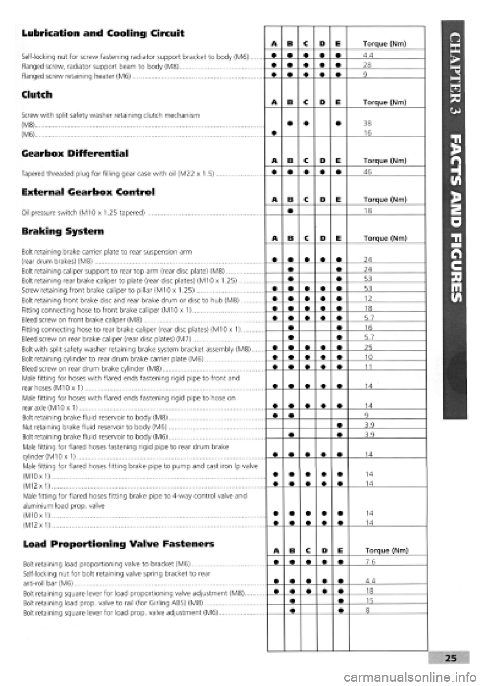
Lubrication and Cooling Circuit
Self-locking nut for screw fastening radiator support bracket to body (M6)....
Flanged screw, radiator support beam to body (M8)
Flanged screw retaining heater (M6)
Clutch
Screw with split safety washer retaining clutch mechanism
(M8)
(M6)
Gearbox Differential
Tapered threaded plug for filling gear case with oil (M22 x 1.5)
External Gearbox Control
Oil pressure switch (M10 x 1.25 tapered)
Braking System
Bolt retaining brake carrier plate to rear suspension arm
(rear drum brakes) (M8)
Bolt retaining caliper support to rear top arm (rear disc plate) (M8)
Bolt retaining rear brake caliper to plate (rear disc plates) (M10 x 1.25)
Screw retaining front brake caliper to pillar (M10 x 1.25)
Bolt retaining front brake disc and rear brake drum or disc to hub (M8)
Fitting connecting hose to front brake caliper (M10 x 1)
Bleed screw on front brake caliper (M8)
Fitting connecting hose to rear brake caliper (rear disc plates) (M10 x 1)
Bleed screw on rear brake caliper (rear disc plates) (M7)
Bolt with split safety washer retaining brake system bracket assembly (M8)....
Bolt retaining cylinder to rear drum brake carrier plate (M6)
Bleed screw on rear drum brake cylinder (M8)
Male fitting for hoses with flared ends fastening rigid pipe to front and
rear hoses (M10 x 1)
Male fitting for hoses with flared ends fastening rigid pipe to hose on
rear axle (M10 x 1)
Bolt retaining brake fluid reservoir to body (M8)
Nut retaining brake fluid reservoir to body (M6)
Bolt retaining brake fluid reservoir to body (M6)
Male fitting for flared hoses fastening rigid pipe to rear drum brake
cylinder
(M1
Ox 1)
Male fitting for flared hoses fitting brake pipe to pump and cast iron Ip valve
(M10
x
1)
(M12
x
1)
Male fitting for flared hoses fitting brake pipe to 4-way control valve and
aluminium load prop, valve
(M10 x
1)
(M12
x
1)
Load Proportioning Valve Fasteners
Bolt retaining load proportioning valve to bracket (M6)
Self-locking nut for bolt retaining valve spring bracket to rear
anti-roll bar (M6)
Bolt retaining square lever for load proportioning valve adjustment (M8)
Bolt retaining load prop, valve to rail (for Girling ABS) (M8)
Bolt retaining square lever for load prop, valve adjustment (M6)
Page 29 of 171
Thanks
are due to the excellent, knowledgeable and helpful staff at FIAT main dealers, Ryauto of Amblecote, in the West
Midlands for supplying vehicles and for their assistance with this chapter. In particular, thanks are due to the efficient Maurice
Hough, Service Manager, the experienced Foreman, Tony Morris, and young demon mechanic, Matthew Worsfold.
Some of the suggested inspection/replacement intervals may not correspond to those shown in the original handbook. The suggested
schedule, based on FIAT'S recommendations, takes into account the age of the vehicle and the annual MoT test in the UK.
In practice, because of the split between (mainly) 12 month/9,000 mile and 18 month/13,500 mile intervals, you will need to
service your Tipo or Tempra at most, if not every, 6 month interval.
IMPORTANT NOTE: Each service should be carried out at EITHER the recommended mileage OR the recommended time
interval, whichever comes first.
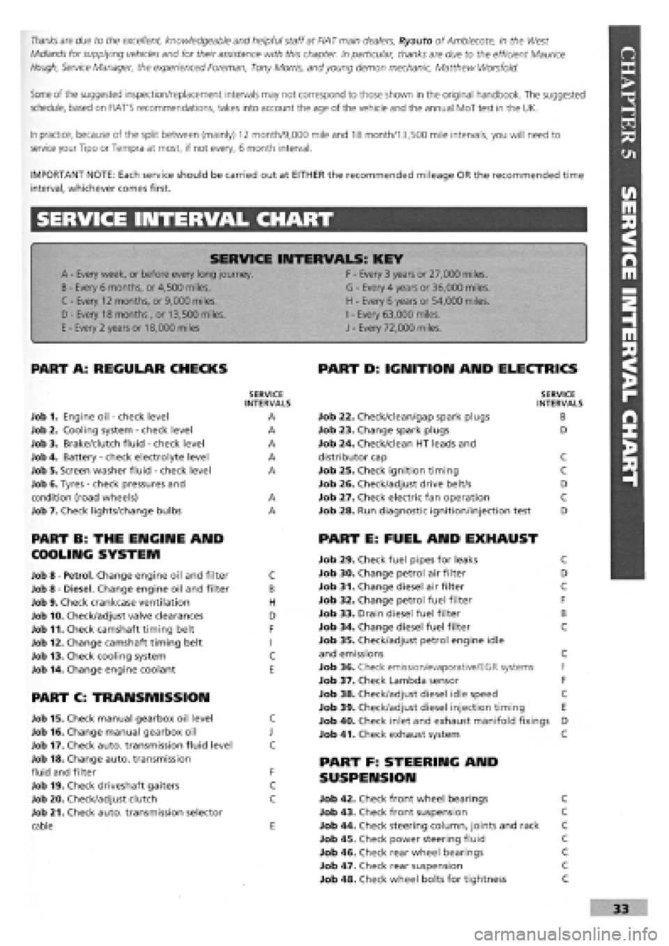
SERVICE INTERVAL CHART
SERVICE INTERVALS: KEY
A
-
Every week, or before every long journey. F
-
Every 3 years or 27,000 miles.
B
-
Every 6 months, or 4,500 miles. G
-
Every 4 years or 36,000 miles.
C - Every 12 months, or 9,000 miles. H
-
Every 6 years or 54,000 miles.
I
-
Every 63,000 miles. D - Every 18 months , or 13,500 miles.
H
-
Every 6 years or 54,000 miles.
I
-
Every 63,000 miles.
E
-
Every 2 years or 18,000 miles J
-
Every 72,000 miles.
PART A: REGULAR CHECKS
SERVICE INTERVALS
Job 1. Engine oil
-
check level A
Job 2. Cooling system
-
check level A
Job 3. Brake/clutch fluid
-
check level A
Job 4. Battery
-
check electrolyte level A
Job 5. Screen washer fluid
-
check level A
Job 6. Tyres
-
check pressures and
condition (road wheels) A
Job 7. Check lights/change bulbs A
PART B: THE ENGINE AND
COOLING SYSTEM
Job 8
-
Petrol. Change engine oil and filter C
Job 8
-
Diesel. Change engine oil and filter B
Job 9. Check crankcase ventilation H
Job 10. Check/adjust valve clearances D
Job 11. Check camshaft timing belt F
Job 12. Change camshaft timing belt I
Job 13. Check cooling system C
Job 14. Change engine coolant E
PART C: TRANSMISSION
Job 15. Check manual gearbox oil level C
Job 16. Change manual gearbox oil J
Job 17. Check auto, transmission fluid level C
Job 18. Change auto, transmission
fluid and filter F
Job 19. Check driveshaft gaiters C
Job 20. Check/adjust clutch C
Job 21. Check auto, transmission selector
cable E
PART D: IGNITION AND ELECTRICS
SERVICE INTERVALS
Job 22. Check/clean/gap spark plugs B
Job 23. Change spark plugs D
Job 24. Check/clean HT leads and
distributor cap C
Job 25. Check ignition timing C
Job 26. Check/adjust drive belt/s D
Job 27. Check electric fan operation C
Job 28. Run diagnostic ignition/injection test D
PART E: FUEL AND EXHAUST
Job 29. Check fuel pipes for leaks C
Job 30. Change petrol air filter D
Job 31. Change diesel air filter C
Job 32. Change petrol fuel filter F
Job 33. Drain diesel fuel filter B
Job 34. Change diesel fuel filter C
Job 35. Check/adjust petrol engine idle
and emissions C
Job 36. Check emission/evaporative/EGR systems F
Job 37. Check Lambda sensor F
Job 38. Check/adjust diesel idle speed C
Job 39. Check/adjust diesel injection timing E
Job 40. Check inlet and exhaust manifold fixings D
Job 41. Check exhaust system C
PART F: STEERING AND
SUSPENSION
Job 42. Check front wheel bearings C
Job 43. Check front suspension C
Job 44. Check steering column, joints and rack C
Job 45. Check power steering fluid C
Job 46. Check rear wheel bearings C
Job 47. Check rear suspension C
Job 48. Check wheel bolts for tightness C
Page 31 of 171
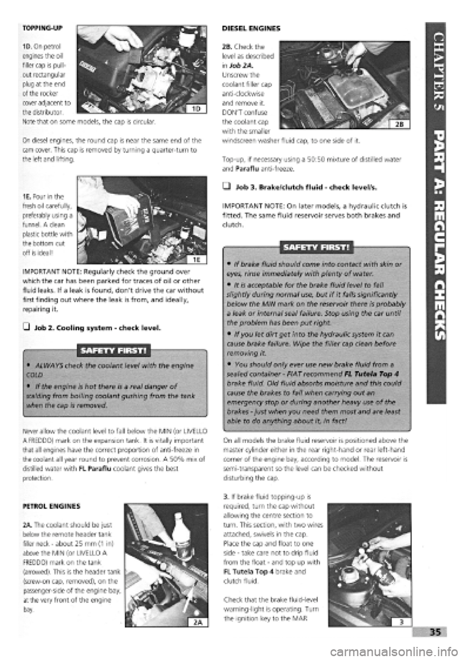
TOPPING-UP
1D. On petrol
engines the oil
filler cap is pull-
out rectangular
plug at the end
of the rocker
On diesel engines, the round cap is near the same end of the
cam cover. This cap is removed by turning a quarter-turn to
the left and lifting.
DIESEL ENGINES
Top-up, if necessary using a 50:50 mixture of distilled water
and Paraflu anti-freeze.
cover adjacent to
the distributor.
Note that on some models, the cap is circular.
1E. Pour in the
fresh oil carefully,
preferably using a
funnel. A clean
plastic bottle with
the bottom cut
off is ideal!
IMPORTANT NOTE: Regularly check the ground over
which the car has been parked for traces of oil or other
fluid leaks. If a leak is found, don't drive the car without
first finding out where the leak is from, and ideally,
repairing it.
G Job 2. Cooling system
-
check level.
SAFETY FIRST!
• ALWAYS check the coolant level with the engine
COLD
• If the engine is hot there is a real danger of
scalding
from boiling coolant gushing from the tank
when the cap is removed.
Never allow the coolant level to fall below the MIN (or UVELLO
A FREDDO) mark on the expansion tank. It is vitally important
that all engines have the correct proportion of anti-freeze in
the coolant all year round to prevent corrosion. A 50% mix of
distilled water with FL Paraflu coolant gives the best
protection.
• Job 3. Brake/dutch fluid
-
check level/s.
IMPORTANT NOTE: On later models, a hydraulic clutch is
fitted. The same fluid reservoir serves both brakes and
clutch.
SAFETY FIRST!
• If brake fluid should come into contact with skin or
eyes, rinse immediately with plenty of water.
• It is acceptable for the brake fluid level to fall
slightly during normal use, but if it falls significantly
below the MIN mark on the reservoir there is probably
a leak or internal seal failure. Stop using the car until
the problem has been put right.
• If you let dirt get into the hydraulic system it can
cause brake failure. Wipe the filler cap clean before
removing it.
• You should only ever use new brake fluid from a
sealed container
-
FIAT recommend FL Tutela Top 4
brake fluid. Old fluid absorbs moisture and this could
cause the brakes to fail when carrying out an
emergency stop or during another heavy use of the
brakes
-
just when you need them most and are least
able to do anything about it, in fact!
On all models the brake fluid reservoir is positioned above the
master cylinder either in the rear right-hand or rear left-hand
corner of the engine bay, according to model. The reservoir is
semi-transparent so the level can be checked without
disturbing the cap.
PETROL ENGINES
2A. The coolant should be just
below the remote header tank
filler neck
-
about 25 mm
(1
in)
above the MIN (or UVELLO A
FREDDO) mark on the tank
(arrowed). This is the header tank
(screw-on cap, removed), on the
passenger-side of the engine bay,
at
the very front of the engine
bay.
3. If brake fluid topping-up is
required, turn the cap without
allowing the centre section to
turn. This section, with two wires
attached, swivels in the cap.
Place the cap and float to one
side
-
take care not to drip fluid
from the float
-
and top up with
FL Tutela Top 4 brake and
clutch fluid.
Check that the brake fluid-level
warning-light is operating. Turn
the ignition key to the MAR
I
i 3
»35
2B. Check the
level as described
in
Job 2A.
Unscrew the
coolant filler cap
anti-clockwise
and remove it.
DON'T confuse
the coolant cap
with the smaller
windscreen washer fluid cap, to one side of it.
Page 36 of 171
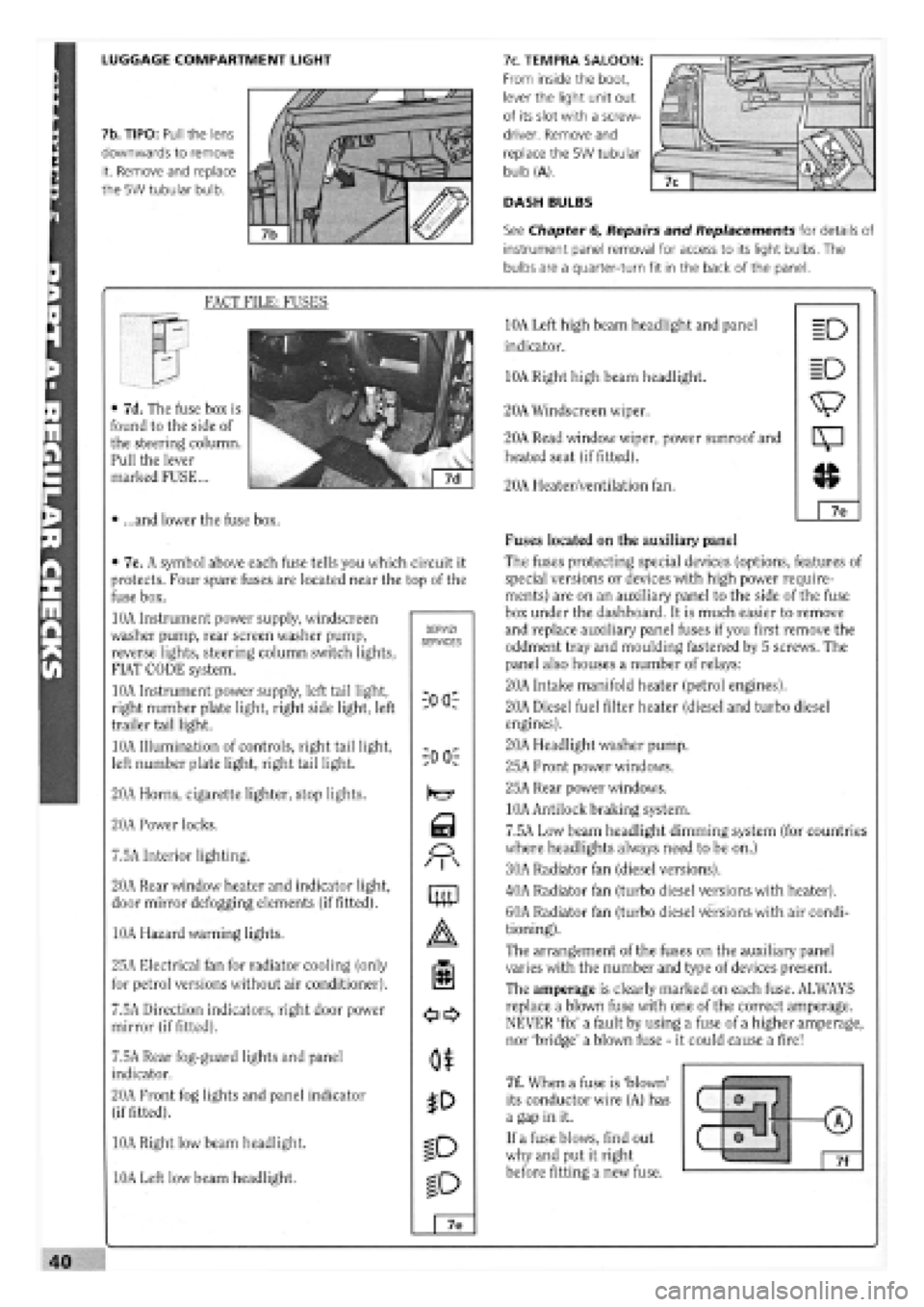
LUGGAGE COMPARTMENT LIGHT
7b. TIPO: Pull the lens
downwards to remove
it. Remove and replace
the 5W tubular bulb.
7c. TEMPRA SALOON:
From inside the boot,
lever the light unit out
of its slot with a screw-
driver. Remove and
replace the 5W tubular
bulb (A).
DASH BULBS
See Chapter 6, Repairs and Replacements for details of
instrument panel removal for access to its light bulbs. The
bulbs are a quarter-turn fit in the back of the panel.
FACT FILE: FUSES
• 7d. The fuse box is
found to the side of
the steering column.
Pull the lever
marked FUSE...
• ...and lower the fuse box.
• 7e. A symbol above each fuse tells you which circuit it
protects. Four spare fuses are located near the top of the
fuse box.
10A Instrument power supply, windscreen
washer pump, rear screen washer pump,
reverse lights, steering column switch lights,
FIAT CODE system.
10A Instrument power supply, left tail light,
right number plate light, right side light, left
trailer tail light.
10A Illumination of controls, right tail light,
left number plate light, right tail light.
20A Horns, cigarette lighter, stop lights.
20A Power locks.
7.5A Interior lighting.
20A Rear window heater and indicator light,
door mirror defogging elements (if fitted).
10A Hazard warning lights.
25A Electrical fan for radiator cooling (only
for petrol versions without air conditioner).
7.5A Direction indicators, right door power
mirror (if fitted).
7.5A Rear fog-guard lights and panel
indicator.
20A Front fog lights and panel indicator
(if fitted).
10A Right low beam headlight.
10A Left low beam headlight.
SERVIZI SERVICES
iOO:
-00 r
Q
M
mp
o$
ID
ID
7e
10A Left high beam headlight and panel
indicator.
10A Right high beam headlight.
20A Windscreen wiper.
20A Read window wiper, power sunroof and
heated seat (if fitted).
20A Heater/ventilation fan.
Fuses located on the auxiliary panel
The fuses protecting special devices (options, features of
special versions or devices with high power require-
ments) are on an auxiliary panel to the side of the fuse
box under the dashboard. It is much easier to remove
and replace auxiliary panel fuses if you first remove the
oddment tray and moulding fastened by 5 screws. The
panel also houses a number of relays:
20A Intake manifold heater (petrol engines).
20A Diesel fuel filter heater (diesel and turbo diesel
engines).
20A Headlight washer pump.
25A Front power windows.
25A Rear power windows.
10A Antilock braking system.
7.5A Low beam headlight dimming system (for countries
where headlights always need to be on.)
30A Radiator fan (diesel versions).
40A Radiator fan (turbo diesel versions with heater).
60A Radiator fan (turbo diesel versions with air condi-
tioning).
The arrangement of the fuses on the auxiliary panel
varies with the number and type of devices present.
The amperage is clearly marked on each fuse. ALWAYS
replace a blown fuse with one of the correct amperage.
NEVER 'fix' a fault by using a fuse of a higher amperage,
nor 'bridge' a blown fuse
-
it could cause a fire!
7f. When a fuse is 'blown'
its conductor wire (A) has
a gap in it.
If a fuse blows, find out
why and put it right
before fitting a new fuse.
(7)
o m f (7) (7)
0 tJ 7f
Page 37 of 171
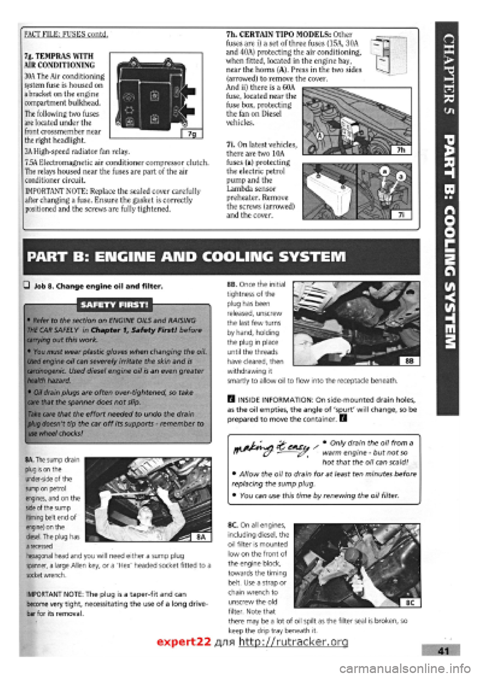
FACT FILE: FUSES contd. 7h. CERTAIN TIPO MODELS: Other
fuses are i) a set of three fuses (15A, 30A
and 40A) protecting the air conditioning,
when fitted, located in the engine bay,
near the horns (A). Press in the two sides
(arrowed) to remove the cover.
And ii) there is a 60A
fuse, located near the
fuse box, protecting
the fan on Diesel
vehicles.
7i. On latest vehicles,
there are two 10A
fuses (a) protecting
the electric petrol
pump and the
Lambda sensor
preheater. Remove
the screws (arrowed)
and the cover.
7g. TEMPRAS WITH
AIR CONDITIONING
30A The Air conditioning
system fuse is housed on
a bracket on the engine
compartment bulkhead.
The following two fuses
are located under the
front crossmember near
the right headlight.
3A High-speed radiator fan relay.
7.5A Electromagnetic air conditioner compressor clutch.
The relays housed near the fuses are part of the air
conditioner circuit.
IMPORTANT NOTE: Replace the sealed cover carefully
after changing a fuse. Ensure the gasket is correctly
positioned and the screws are fully tightened.
PART B: ENGIIME AND COOLING SYSTEM
Q Job 8. Change engine oil and filter.
SAFETY FIRST!
• Refer to the section on ENGINE OILS and RAISING
THE
CAR SAFELY in Chapter f, Safety First! before
carrying
out this work.
• You must wear plastic gloves when changing the oil.
Used
engine oil can severely irritate the skin and
is
carcinogenic.
Used diesel engine oil is an even greater
health
hazard.
•
Oil
drain plugs are often over-tightened, so take
care
that the spanner does not slip.
Take
care that the effort needed to undo the drain
plug
doesn't tip the car off its supports
-
remember to
use
wheel
chocks!
rtj&^si ' # °nly dram theu 0,7 fr°m a ff (y warm engine
-
but not
so
hot that the oil can scald!
• Allow the oil to drain for at least ten minutes before
replacing the sump plug.
• You can use this time by renewing the oil filter.
IMPORTANT NOTE: The plug is a taper-fit and can
become very tight, necessitating the use of a long drive-
bar for its removal.
H INSIDE INFORMATION: On side-mounted drain holes,
as the oil empties, the angle of 'spurt' will change, so be
prepared to move the container. E3
8A. The
sump drain
plug is on
the
under-side of the
sump on
petrol
engines, and on the
side
of the sump
(timing belt end of
engine) on the
diesel.
The plug has
a
recessed
hexagonal head and you will need either a sump plug
spanner, a large Allen key, or a 'Hex' headed socket fitted to a
socket
wrench.
8B. Once the initial
tightness of the
plug has been
released, unscrew
the last few turns
by hand, holding
the plug in place
until the threads
have cleared, then
withdrawing it
smartly to allow oil to flow into the receptacle beneath.
expert22
8C. On all engines,
including diesel, the
oil filter is mounted
low on the front of
the engine block,
towards the timing
belt. Use a strap or
chain wrench to
unscrew the old
filter. Note that
there may be a lot of oil spilt as the filter seal is broken, so
keep the drip tray beneath it.
/yifl http://rutracker.org
Page 39 of 171
—I Job 13. Check cooling system.
SAFETY FIRST!
• The coolant level should be checked
-
and the
cooling system worked on, ONLY WHEN THE
COOLANT IS COLD. If you remove the pressure cap or
bleed screws when the engine is hot, scalding coolant
will spurt out.
• Keep anti-freeze away from children. If it is acciden-
tally swallowed or contacts skin or eyes, rinse
immediately with plenty of water and seek immediate
medical help.
Examine the cooling system hoses, looking for signs of
splitting, chafing and perishing. Squeeze the top and bottom
radiator hoses. Any hard, brittle areas or crackling sounds tell
you that the hoses are decomposing from the inside
-
replace-
ments needed!
SAFETY FIRST!
If
a
clearance is outside the tolerances shown in Chapter 3,
Facts
and Figures, the relevant shim will have to be changed.
New
shims
are available from your FIAT dealer. This work is
fully described in Chapter
6,
Repairs and Replacements.
10E. You must
always use a new
gasket, especially in
view of the oil level
mentioned earlier.
Clean the housing
and
cover faces and
use
the gasket dry.
11.
Examine the
belt
for wear. If
there
is
any
cracking, or if the
toothed side
10F.H INSIDE
INFORMATION:
The cover is 'anti-
crush'
-
you CAN'T
tighten beyond
the lugs pointed
out here
-
so
there's no point
trying! H
0 Job 11. Check camshaft timing belt.
Remove the camshaft belt outer cover. See Chapter 6,
Repairs
and Replacements, PART A: ENGINE.
FACT FILE: VALVE IDENTIFICATION:
T
—
Remember that clearances for inlet and
3™ exhaust valves differ. See
Chapter
3,
Facts and Figures. Counting from the
—^ timing belt end the valves are:
1.1,1.2 8-valve AND DIESEL ENGINES:
EXHAUST -1, 3, 6, 8. INLET
-
2, 4, 5, 7.
1372cc AND 1581cc ENGINES: EXHAUST -1, 4, 5, 8.
INLET
-
2, 3, 6, 7.
1.2 16-valve Hydraulic tappets
-
non-adjustable.
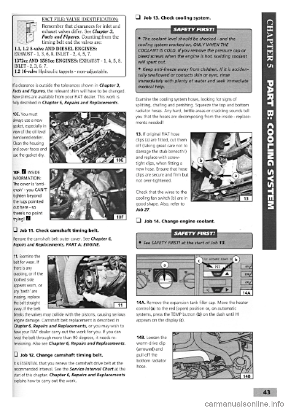
13. If original FIAT hose
clips (a) are fitted, cut them
off (taking great care not to
damage the stub beneath!)
and replace with screw-
tight clips, when fitting a
new hose. Ensure that hose
clips are secure and firm but
not over-tightened.
Check that the wires to the
cooling fan switch (b) are in
good shape. Also, refer to
Job
27
• Job 14. Change engine coolant.
• See SAFETY FIRST! at the start of Job 13.
appears worn, or
any 'teeth' are
missing, replace
the belt straight
away. If the belt
breaks
the valves may collide with the pistons, causing serious
engine damage. Camshaft belt replacement is described in
Chapter 6,
Repairs and Replacements, or you may wish to
have
your FIAT dealer carry out the work for you. If you can
twist the belt through more than 90 degrees, it needs re-
tensioning. Also see Chapter
6,
Repairs and Replacements.
m
AUtOKAlIC CtMAU s/
b
14A. Remove the expansion tank filler cap. Move the heater
control (a) to the red (open) position or, on automatic
systems, press the TEMP button (b) on the dash until HI
appears on the display (c).
—i Job 12. Change camshaft timing belt.
It is
ESSENTIAL that you renew the camshaft drive belt at the
recommended interval. See the Service Interval Chart at the
start
of this chapter. Chapter
6,
Repairs and Replacements
explains how to carry out the work.
14B. Loosen the
worm-drive clip
(arrowed) and
pull off the
bottom radiator
hose.