display FIAT TEMPRA 1988 Service And Repair Manual
[x] Cancel search | Manufacturer: FIAT, Model Year: 1988, Model line: TEMPRA, Model: FIAT TEMPRA 1988Pages: 171, PDF Size: 18.05 MB
Page 6 of 171
• Repeat this operation three more times until the
complete code number has been entered, if the code
has been entered in correctly LED B will start flashing.
• Release button A (see illustration
1B).
Red LED B
flashes for 8 seconds indicating the new remote unit's
code has been stored.
IMPORTANT NOTE: If the LED does not illuminate
when remote unit button (illustration 1B, button
O is pressed, change the remote unit's battery.
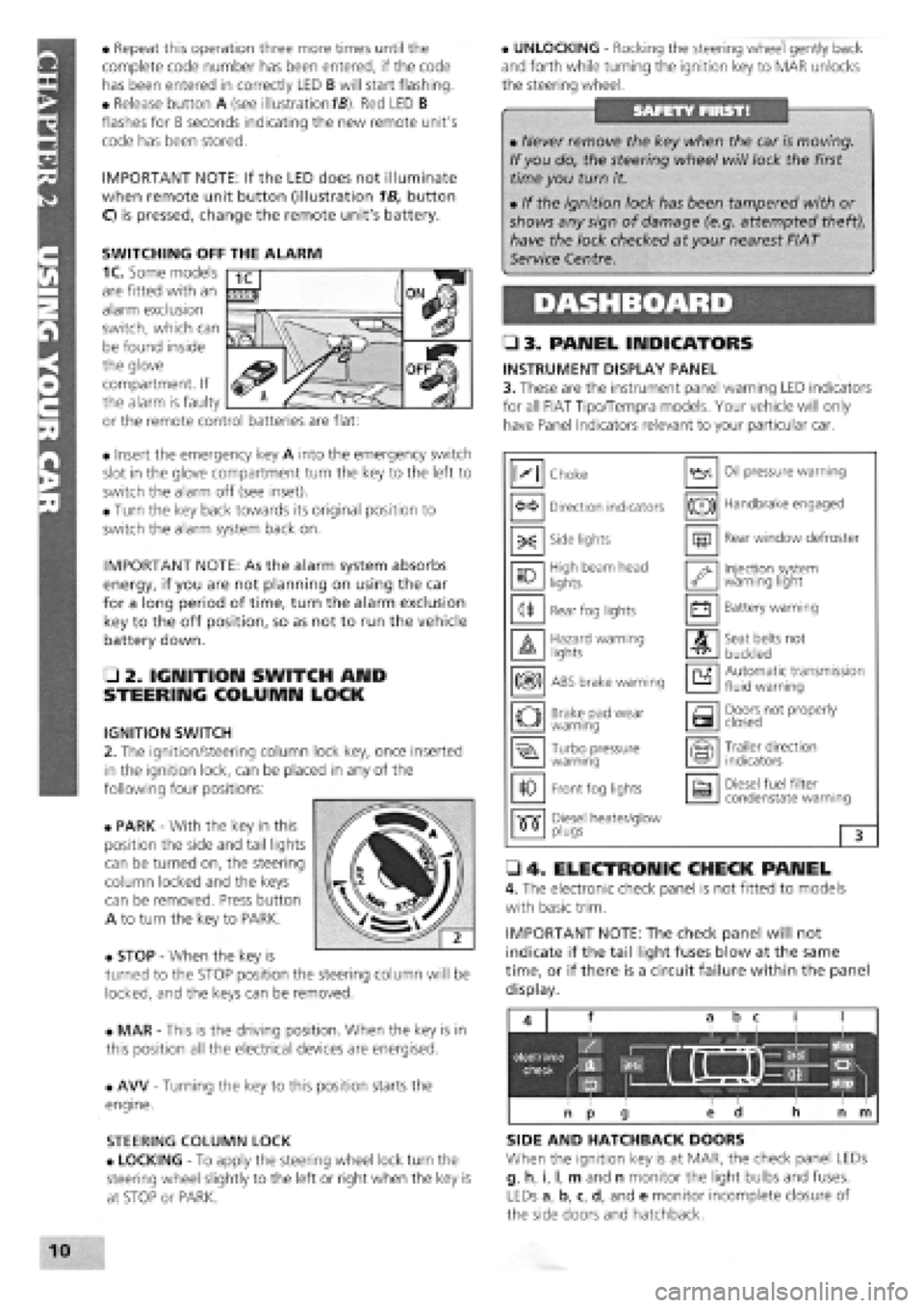
• Insert the emergency key A into the emergency switch
slot in the glove compartment turn the key to the left to
switch the alarm off (see inset).
• Turn the key back towards its original position to
switch the alarm system back on.
IMPORTANT NOTE: As the alarm system absorbs
energy, if you are not planning on using the car
for a long period of time, turn the alarm exclusion
key to the off position, so as not to run the vehicle
battery down.
• 2. IGNITION SWITCH AND
STEERING COLUMN LOCK
IGNITION SWITCH
2. The ignition/steering column lock key, once inserted
in the ignition lock, can be placed in any of the
following four positions:
• PARK
-
With the key in this
position the side and tail lights
can be turned on, the steering
column locked and the keys
can be removed. Press button
A to turn the key to PARK.
• STOP
-
When the key is
turned to the STOP position the steering column will be
locked, and the keys can be removed.
• MAR
-
This is the driving position. When the key is in
this position all the electrical devices are energised.
• AW
-
Turning the key to this position starts the
engine.
STEERING COLUMN LOCK
• LOCKING
-
To apply the steering wheel lock turn the
steering wheel slightly to the left or right when the key is
at STOP or PARK.
• UNLOCKING
-
Rocking the steering wheel gently back
and forth while turning the ignition key to MAR unlocks
the steering wheel.
• 3. PANEL INDICATORS
INSTRUMENT DISPLAY PANEL
3. These are the instrument panel warning LED indicators
for all FIAT Tipo/Tempra models. Your vehicle will only
have Panel Indicators relevant to your particular car.
• 4. ELECTRONIC CHECK PANEL
4. The electronic check panel is not fitted to models
with basic trim.
IMPORTANT NOTE: The check panel will not
indicate if the tail light fuses blow at the same
time, or if there is a circuit failure within the panel
display.
SIDE AND HATCHBACK DOORS
When the ignition key is at MAR, the check panel LEDs
g, h, i, I, m and n monitor the light bulbs and fuses.
LEDs a, b, c, d, and e monitor incomplete closure of
the side doors and hatchback.
• Never remove the key when the car is moving.
If you do, the steering wheel will lock the first
time you turn it.
• If the ignition lock has been tampered with or
shows any sign of damage (e.g. attempted theft),
have the lock checked at your nearest FIAT
Service Centre.
M Choke Oil pressure warning
Direction indicators (®) Handbrake engaged
-X: Side lights m Rear window defroster
10 High beam head
lights '•y Injection system warning light
<1* Rear fog lights • Battery warning
A Hazard warning lights A Seat belts not
buckled
m ABS brake warning a Automatic transmission fluid warning
o Brake pad wear warning a Doors not properly closed
Turbo pressure warning Trailer direction indicators
10 Front fog lights a Diesel fuel filter condenstate warning
•515" Diesel heater/glow •515" plugs 3
SWITCHING OFF THE ALARM
1C. Some models
are fitted with an
alarm exclusion
switch, which can
be found inside
the glove
compartment. If
the alarm is faulty
or the remote control batteries are flat:
Page 8 of 171
AIR CONDITIONING (EARLY MODELS)
Air conditioning is an optional extra fitted to some
models of Tipo and Tempra.
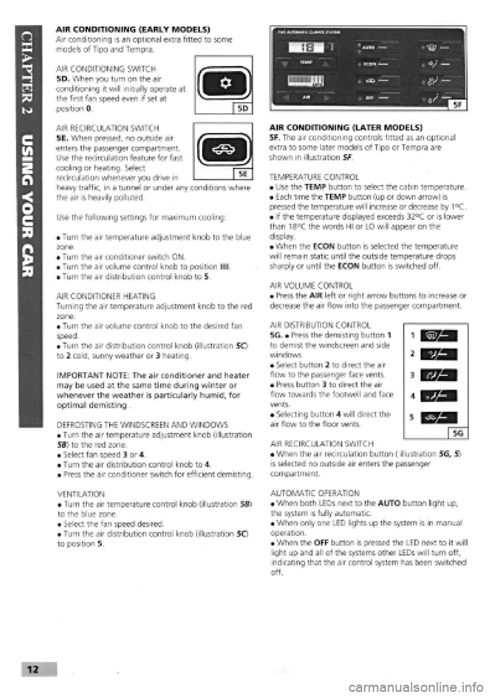
AIR CONDITIONING SWITCH
5D. When you turn on the air
conditioning it will initially operate at
the first fan speed even if set at
position 0.
AIR RECIRCULATION SWITCH
5E. When pressed, no outside air
enters the passenger compartment.
Use the recirculation feature for fast
cooling or heating. Select
recirculation whenever you drive in
heavy traffic, in a tunnel or under any conditions where
the air is heavily polluted.
Use the following settings for maximum cooling:
• Turn the air temperature adjustment knob to the blue
zone.
• Turn the air conditioner switch ON.
• Turn the air volume control knob to position Mil.
• Turn the air distribution control knob to 5.
AIR CONDITIONER HEATING
Turning the air temperature adjustment knob to the red
zone:
• Turn the air volume control knob to the desired fan
speed.
• Turn the air distribution control knob (illustration 50
to 2 cold, sunny weather or 3 heating.
IMPORTANT NOTE: The air conditioner and heater
may be used at the same time during winter or
whenever the weather is particularly humid, for
optimal demisting .
DEFROSTING THE WINDSCREEN AND WINDOWS
• Turn the air temperature adjustment knob (illustration
56) to the red zone.
• Select fan speed 3 or 4.
• Turn the air distribution control knob to 4.
• Press the air conditioner switch for efficient demisting.
VENTILATION
• Turn the air temperature control knob (illustration SB)
to the blue zone.
• Select the fan speed desired.
• Turn the air distribution control knob (illustration 50
to position 5.
AIR CONDITIONING (LATER MODELS)
5F. The air conditioning controls fitted as an optional
extra to some later models of Tipo or Tempra are
shown in illustration 5F
TEMPERATURE CONTROL
• Use the TEMP button to select the cabin temperature.
• Each time the TEMP button (up or down arrow) is
pressed the temperature will increase or decrease by 1°C.
• If the temperature displayed exceeds 32°C or is lower
than 18°C the words HI or LO will appear on the
display.
• When the ECON button is selected the temperature
will remain static until the outside temperature drops
sharply or until the ECON button is switched off.
AIR VOLUME CONTROL
• Press the AIR left or right arrow buttons to increase or
decrease the air flow into the passenger compartment.
AIR DISTRIBUTION CONTROL
5G. • Press the demisting button 1
to demist the windscreen and side
windows.
• Select button 2 to direct the air
flow to the passenger face vents.
• Press button 3 to direct the air
flow towards the footwell and face
vents.
• Selecting button 4 will direct the
air flow to the floor vents.
AIR RECIRCULATION SWITCH
• When the air recirculation button (illustration 5G, 5)
is selected no outside air enters the passenger
compartment.
AUTOMATIC OPERATION
• When both LEDs next to the AUTO button light up,
the system is fully automatic.
• When only one LED lights up the system is in manual
operation.
• When the OFF button is pressed the LED next to it will
light up and all of the systems other LEDs will turn off,
indicating that the air control system has been switched
off.
vh
5G
Page 9 of 171
CONTROLS
• 6. LIGHTS AND INDICATORS
DIRECTION INDICATORS AND REAR FOG LIGHT
SWITCH
The lights operate when the key is at the MAR position.
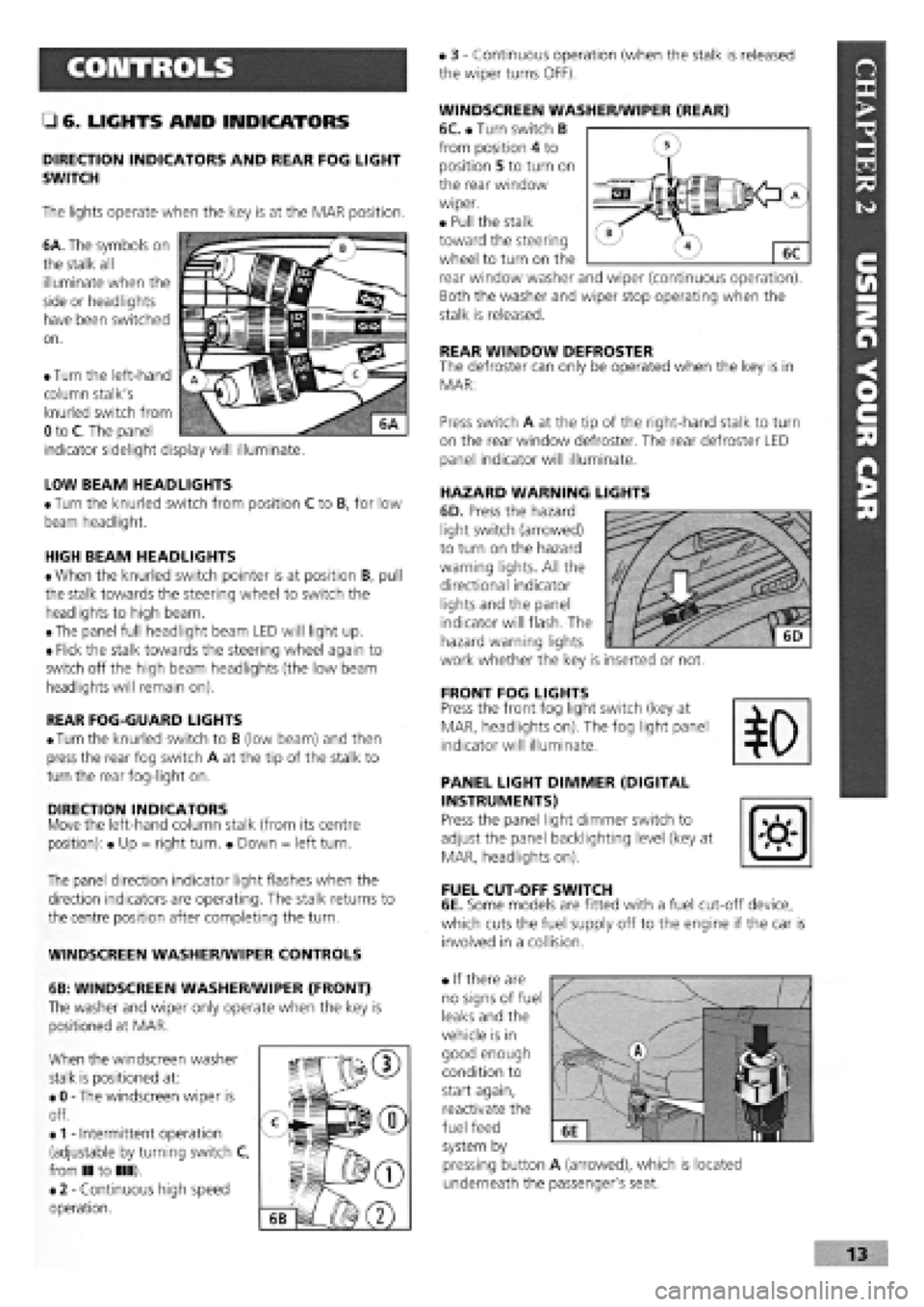
6A. The symbols on
the stalk all
illuminate when the
side or headlights
have been switched
on.
• 3
-
Continuous operation (when the stalk is released
the wiper turns OFF).
WINDSCREEN WASHER/WIPER (REAR)
6C. • Turn switch B
from position 4 to
position 5 to turn on
the rear window
wiper.
• Pull the stalk
toward the steering
wheel to turn on the
rear window washer and wiper (continuous operation).
Both the washer and wiper stop operating when the
stalk is released.
REAR WINDOW DEFROSTER The defroster can only be operated when the key is in
MAR:
LOW BEAM HEADLIGHTS
• Turn the knurled switch from position C to B, for low
beam headlight.
HIGH BEAM HEADLIGHTS
• When the knurled switch pointer is at position B, pull
the stalk towards the steering wheel to switch the
headlights to high beam.
• The panel full headlight beam LED will light up.
• Flick the stalk towards the steering wheel again to
switch off the high beam headlights (the low beam
headlights will remain on).
REAR FOG-GUARD LIGHTS
•
Turn
the knurled switch to B (low beam) and then
press the rear fog switch A at the tip of the stalk to
turn the rear fog-light on.
DIRECTION INDICATORS Move the left-hand column stalk (from its centre
position): • Up = right turn. • Down = left turn.
The panel direction indicator light flashes when the
direction indicators are operating. The stalk returns to
the centre position after completing the turn.
WINDSCREEN WASHER/WIPER CONTROLS
6B: WINDSCREEN WASHER/WIPER (FRONT)
The washer and wiper only operate when the key is
positioned at MAR.
When the windscreen washer
stalk is positioned at:
• 0
-
The windscreen wiper is
off.
•
1 -
Intermittent operation
(adjustable by turning switch C,
from II to III).
• 2
-
Continuous high speed
operation.
Press switch A at the tip of the right-hand stalk to turn
on the rear window defroster. The rear defroster LED
panel indicator will illuminate.
HAZARD WARNING LIGHTS
6D. Press the hazard
light switch (arrowed)
to turn on the hazard
warning lights. All the
directional indicator
lights and the panel
indicator will flash. The
hazard warning lights
work whether the key is inserted or not.
FRONT FOG LIGHTS Press the front fog light switch (key at
MAR, headlights on). The fog light panel
indicator will illuminate.
PANEL LIGHT DIMMER (DIGITAL
INSTRUMENTS)
Press the panel light dimmer switch to
adjust the panel backlighting level (key at
MAR, headlights on).
FUEL CUT-OFF SWITCH
6E. Some models are fitted with a fuel cut-off device,
which cuts the fuel supply off to the engine if the car is
involved in a collision.
• If there are
no signs of fuel
leaks and the
vehicle is in
good enough
condition to
start again,
reactivate the
fuel feed
system by
pressing button A (arrowed), which is located
underneath the passenger's seat.
• Turn the left-hand
column stalk's
knurled switch from
0 to C. The panel
indicator sidelight display will illuminate.
Page 25 of 171
Windscreen and Mirrors
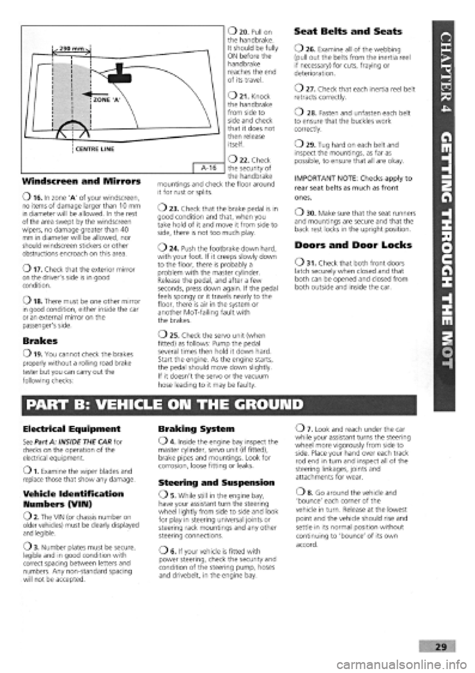
O 16. In zone 'A' of your windscreen, no items of damage larger than 10 mm in diameter will be allowed. In the rest of the area swept by the windscreen wipers, no damage greater than 40 mm in diameter will be allowed, nor should windscreen stickers or other obstructions encroach on this area.
o 17. Check that the exterior mirror on the driver's side is in good condition.
o 18. There must be one other mirror in good condition, either inside the car or an external mirror on the passenger's side.
Brakes
O 19. You cannot check the brakes
properly without a rolling road brake
tester but you can carry out the
following checks:
O 20. Pull on the handbrake. It should be fully ON before the handbrake reaches the end of its travel.
O 21. Knock the handbrake from side to side and check that it does not then release itself.
O 22. Check the security of the handbrake mountings and check the floor around it for rust or splits.
o 23. Check that the brake pedal is in good condition and that, when you take hold of it and move it from side to side, there is not too much play.
o 24. Push the footbrake down hard, with your foot. If it creeps slowly down to the floor, there is probably a problem with the master cylinder. Release the pedal, and after a few seconds, press down again. If the pedal feels spongy or it travels nearly to the floor, there is air in the system or another MoT-failing fault with the brakes.
o 25. Check the servo unit (when
fitted) as follows: Pump the pedal
several times then hold it down hard.
Start the engine. As the engine starts,
the pedal should move down slightly.
If it doesn't the servo or the vacuum
hose leading to it may be faulty.
Seat Belts and Seats
O 26. Examine all of the webbing (pull out the belts from the inertia reel if necessary) for cuts, fraying or deterioration.
o 27. Check that each inertia reel belt retracts correctly.
o 28. Fasten and unfasten each belt to ensure that the buckles work correctly.
o 29. Tug hard on each belt and inspect the mountings, as far as possible, to ensure that all are okay.
IMPORTANT NOTE: Checks apply to
rear seat belts as much as front
ones.
O 30. Make sure that the seat runners and mountings are secure and that the back rest locks in the upright position.
Doors and Door Locks
O 31. Check that both front doors latch securely when closed and that both can be opened and closed from both outside and inside the car.
PART B: VEHICLE ON THE GROUND
Electrical Equipment
See Part A: INSIDE THE CAR for checks on the operation of the electrical equipment.
O 1. Examine the wiper blades and replace those that show any damage.
Vehicle Identification
Numbers (VIIU)
O 2. The VIN (or chassis number on older vehicles) must be clearly displayed and legible.
O 3. Number plates must be secure, legible and in good condition with correct spacing between letters and numbers. Any non-standard spacing will not be accepted.
Braking System
O 4. Inside the engine bay inspect the master cylinder, servo unit (if fitted), brake pipes and mountings. Look for corrosion, loose fitting or leaks.
Steering and Suspension
OS . While still in the engine bay, have your assistant turn the steering wheel lightly from side to side and look for play in steering universal joints or steering rack mountings and any other steering connections.
OE. If your vehicle is fitted with power steering, check the security and condition of the steering pump, hoses and drivebelt, in the engine bay.
O 7. Look and reach under the car while your assistant turns the steering wheel more vigorously from side to side. Place your hand over each track rod end in turn and inspect all of the steering linkages, joints and attachments for wear.
o 8. Go around the vehicle and
'bounce' each corner of the
vehicle in turn. Release at the lowest
point and the vehicle should rise and
settle in its normal position without
continuing to 'bounce' of its own
accord.
Page 39 of 171
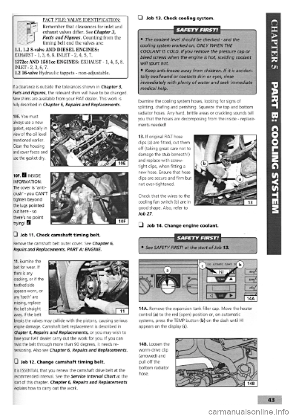
—I Job 13. Check cooling system.
SAFETY FIRST!
• The coolant level should be checked
-
and the
cooling system worked on, ONLY WHEN THE
COOLANT IS COLD. If you remove the pressure cap or
bleed screws when the engine is hot, scalding coolant
will spurt out.
• Keep anti-freeze away from children. If it is acciden-
tally swallowed or contacts skin or eyes, rinse
immediately with plenty of water and seek immediate
medical help.
Examine the cooling system hoses, looking for signs of
splitting, chafing and perishing. Squeeze the top and bottom
radiator hoses. Any hard, brittle areas or crackling sounds tell
you that the hoses are decomposing from the inside
-
replace-
ments needed!
SAFETY FIRST!
If
a
clearance is outside the tolerances shown in Chapter 3,
Facts
and Figures, the relevant shim will have to be changed.
New
shims
are available from your FIAT dealer. This work is
fully described in Chapter
6,
Repairs and Replacements.
10E. You must
always use a new
gasket, especially in
view of the oil level
mentioned earlier.
Clean the housing
and
cover faces and
use
the gasket dry.
11.
Examine the
belt
for wear. If
there
is
any
cracking, or if the
toothed side
10F.H INSIDE
INFORMATION:
The cover is 'anti-
crush'
-
you CAN'T
tighten beyond
the lugs pointed
out here
-
so
there's no point
trying! H
0 Job 11. Check camshaft timing belt.
Remove the camshaft belt outer cover. See Chapter 6,
Repairs
and Replacements, PART A: ENGINE.
FACT FILE: VALVE IDENTIFICATION:
T
—
Remember that clearances for inlet and
3™ exhaust valves differ. See
Chapter
3,
Facts and Figures. Counting from the
—^ timing belt end the valves are:
1.1,1.2 8-valve AND DIESEL ENGINES:
EXHAUST -1, 3, 6, 8. INLET
-
2, 4, 5, 7.
1372cc AND 1581cc ENGINES: EXHAUST -1, 4, 5, 8.
INLET
-
2, 3, 6, 7.
1.2 16-valve Hydraulic tappets
-
non-adjustable.
13. If original FIAT hose
clips (a) are fitted, cut them
off (taking great care not to
damage the stub beneath!)
and replace with screw-
tight clips, when fitting a
new hose. Ensure that hose
clips are secure and firm but
not over-tightened.
Check that the wires to the
cooling fan switch (b) are in
good shape. Also, refer to
Job
27
• Job 14. Change engine coolant.
• See SAFETY FIRST! at the start of Job 13.
appears worn, or
any 'teeth' are
missing, replace
the belt straight
away. If the belt
breaks
the valves may collide with the pistons, causing serious
engine damage. Camshaft belt replacement is described in
Chapter 6,
Repairs and Replacements, or you may wish to
have
your FIAT dealer carry out the work for you. If you can
twist the belt through more than 90 degrees, it needs re-
tensioning. Also see Chapter
6,
Repairs and Replacements.
m
AUtOKAlIC CtMAU s/
b
14A. Remove the expansion tank filler cap. Move the heater
control (a) to the red (open) position or, on automatic
systems, press the TEMP button (b) on the dash until HI
appears on the display (c).
—i Job 12. Change camshaft timing belt.
It is
ESSENTIAL that you renew the camshaft drive belt at the
recommended interval. See the Service Interval Chart at the
start
of this chapter. Chapter
6,
Repairs and Replacements
explains how to carry out the work.
14B. Loosen the
worm-drive clip
(arrowed) and
pull off the
bottom radiator
hose.
Page 98 of 171
Job 8. Automatic gear selector
control cable - replacement.
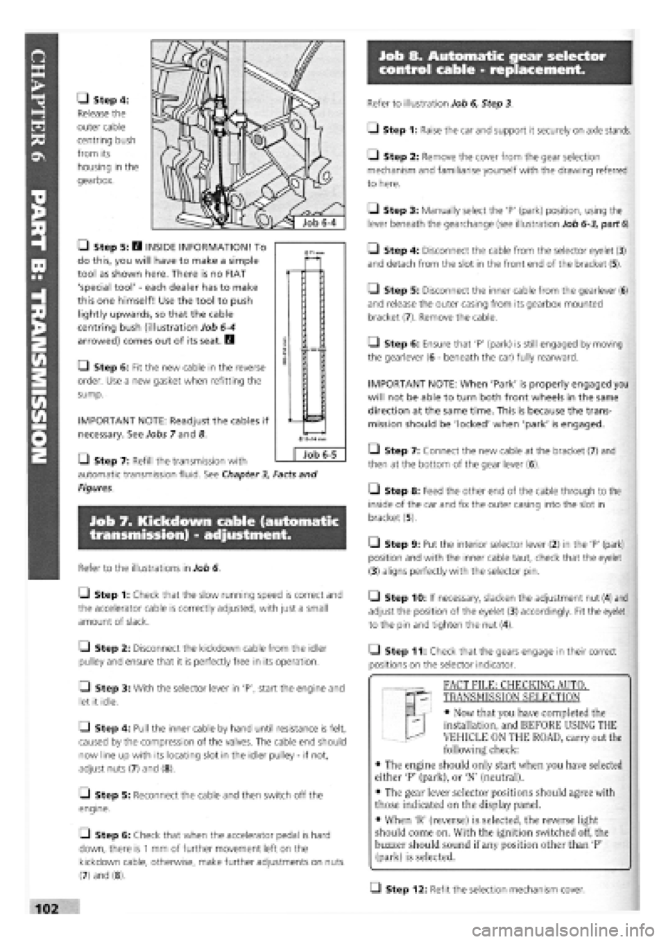
• Step 4:
Release the
outer cable
centring bush
from its
housing in the
gearbox.
• Step 5: H INSIDE INFORMATION! To
do this, you will have to make a simple
tool as shown here. There is no FIAT
'special tool'
-
each dealer has to make
this one himself! Use the tool to push
lightly upwards, so that the cable
centring bush (illustration Job
6-4
arrowed) comes out of its seat. B
• Step 6: Fit the new cable in the reverse
order. Use a new gasket when refitting the
sump.
IMPORTANT NOTE: Readjust the cables if
necessary. See Jobs 7 and 8.
Q Step 7: Refill the transmission with
automatic transmission fluid. See Chapter
3,
Facts and
Figures.
Job 7. Kickdown cable (automatic
transmission) - adjustment.
Refer to the illustrations in Job 6.
Q Step 1: Check that the slow running speed is correct and
the accelerator cable is correctly adjusted, with just a small
amount of slack.
Q Step 2: Disconnect the kickdown cable from the idler
pulley and ensure that it is perfectly free in its operation.
• Step 3: With the selector lever in 'P', start the engine and
let it idle.
Q Step 4: Pull the inner cable by hand until resistance is felt,
caused by the compression of the valves. The cable end should
now line up with its locating slot in the idler pulley
-
if not,
adjust nuts (7) and (8).
[_l Step 5: Reconnect the cable and then switch off the
engine.
• Step 6: Check that when the accelerator pedal is hard
down, there is
1
mm of further movement left on the
kickdown cable, otherwise, make further adjustments on nuts
(7) and (8).
Refer to illustration Job 6, Step 3.
• Step 1: Raise the car and support it securely on axle stands.
• Step 2: Remove the cover from the gear selection
mechanism and familiarise yourself with the drawing referred
to here.
Q Step 3: Manually select the 'P' (park) position, using the
lever beneath the gearchange (see illustration Job
6-3,
part
6).
• Step 4: Disconnect the cable from the selector eyelet (3)
and detach from the slot in the front end of the bracket (5).
Q Step 5: Disconnect the inner cable from the gearlever (6)
and release the outer casing from its gearbox mounted
bracket (7). Remove the cable.
Q Step 6: Ensure that 'P' (park) is still engaged by moving
the gearlever (6
-
beneath the car) fully rearward.
IMPORTANT NOTE: When 'Park' is properly engaged you
will not be able to turn both front wheels in the same
direction at the same time. This is because the trans-
mission should be 'locked' when 'park' is engaged.
• Step 7: Connect the new cable at the bracket (7) and
then at the bottom of the gear lever (6).
• Step 8: Feed the other end of the cable through to the
inside of the car and fix the outer casing into the slot in
bracket (5).
• Step 9: Put the interior selector lever (2) in the 'P' (park)
position and with the inner cable taut, check that the eyelet
(3) aligns perfectly with the selector pin.
• Step 10: If necessary, slacken the adjustment nut (4) and
adjust the position of the eyelet (3) accordingly. Fit the eyelet
to the pin and tighten the nut (4).
• Step 11: Check that the gears engage in their correct
positions on the selector indicator.
T "I FACT FILE: CHECKING AUTOT
qp- TRANSMISSION SELECTION
EL
-
• Now that you have completed the
installation, and BEFORE USING THE
VEHICLE ON THE ROAD, carry out the
following check:
• The engine should only start when you have selected
either 'P' (park), or 'N' (neutral).
• The gear lever selector positions should agree with
those indicated on the display panel.
• When 'R' (reverse) is selected, the reverse light
should come on. With the ignition switched off, the
buzzer should sound if any position other than 'P'
(park) is selected.
Q Step 12: Refit the selection mechanism cover.
0
Job 6-5
Page 152 of 171
97 Solenoid for automatic cold-start advance device 160 Potentiometer 270 Front cable connection (K.S.B.) 161 Junction between engine lead and facia leads for 271 Maximum turbo boost pressure warning light 98 Engine cut out solenoid on injection pump SPI system switch 99 Cooling fan second speed activation relay 161A Engine lead connection for IAW injection system 272 Front cable connection 100 Fuel pump facia lead connection 163 Bosch SPI electronic injection control unit 273 Front cable connection 101 Electromagnetic sensor for rpm sensor 163A Bosch SPI ignition/injection ECU 274 Front cable connection 102 Turbocharger air pressure switch 164 Diagnostic socket (S.P.I.) 281 Left-hand brake lining connection cable joint 104 10A fuse for ABS device 165 Electric fuel pump 281A Right-hand brake lining connection cable joint 105 Connection for anti-lock brake circuit (Antiskid) 166 Hot Lambda probe 282 CO regulation potentiometer 106 Left hand brake lining wear sensor lead 167 Step motor 286 Electromagnetic sensor on flywheel connection 171 Air temperature sender unit 287 Seat belt undone indicator switch 107 Cut-off control module 173 Throttle position sensor 288 Headlight washer intermittent function 108 Cable connection for air conditioner 174 Absolute pressure sender unit 292 Earth for anti-lock brake system (A.B.S.) 109 Front cable connection 180 Rem. contr. switch for legally specified system 293 Earth for air conditioner fan 111 Electric window ECU supply lead connection 181 Daylight side light remote control switch 294 Facia lead connection 112 Sensor on left front wheel 182 Daylight side light remote control switch 295 Connection between facia cable and rear cable 113 Sensor on right front wheel 184 Power earth 297 EGR device ECU 114 Sensor on left rear wheel 185 Electronic earth 298 Diagnostic socket for EGR device 115 Sensor on right rear wheel 186 Electric sun-roof ECU 299 EGR device control solenoid 116 Hydraulic control unit (A.B.S.) 187 Electric sun-roof circuit connection 300 EGR coolant temperature recording sensor 117 ABS control relay 188 Electric sun-roof end-stop sensor microswitch 301 Potentiometer on injection pump 118 Anti-lock brakes electronic control unit (A.B.S.) 189 Sun-roof operating motor 302 Sensor connection cable junction 119 Device for heated filter 190 Safety pressure switch 303 Low engine oil level indication sensor 120 Heated filter device relay 199 IAW multiple relay 304 Low coolant level indication sensor 121 20A fuse for heated filter device 200 Earth on hydraulic control unit bracket 305 Low washer fluid level indication sensor 122 Device for detecting presence of water in fuel filter 200A IAW injection/ignition ECU bracket earth 306 Oil temperature indication sensor 123 Left fog light 207 Starter enablement relay 307 Oil pressure indication sensor 124 Right fog light 208 Switch on gearbox indicating reverse or neutral 308 Junction with coolant temperature sender unit 125 Connection between front cable and fog light 209 Switch on gear selector leads cables 210 Automatic transmission speed selection ECU (CTX) 311 Front cable connection 126 Fog light switch 211 Parking not engaged warning light 312 Front cable connection 127 Sun-roof activation switch 214 Automatic transmission lead connection 313 Junction between facia lead and legally-specified 129 Electric door mirror control switch 215 T.D.C. AND RPM SENSOR (I.A.W.) leads 130 Electrically-adjustable and heated right-hand door 216 Injection/ignition ECU I.A.W. 314 Relay for legally-specified system mirror 219 1st injector 316 60A fuse for air conditioning system 130-A Electrically-adjustable and heated left-hand door 220 2nd injector 317 40A fuse for air conditioner system mirror 221 3rd injector 318 Diagnostic socket for IAW injection system 131 Left headlight wiper motor 222 4th injector 319 Automatic transmission device display 132 Right headlight wiper motor 224 15A fuse for injectors (Volkswagen) 133 Headlight washer pump 225 Idle speed control solenoid A Economy warning light 135 Left front seat heat pads 226 Provision for air conditioner B Sporty drive warning light 135A Right front seat heat pads 228 Ignition distributor with timing sensor 320 Right rear earth for automatic transmission 136 Air conditioner cable connection 231 Coupling with injection lead (Volkswagen) 137 Air conditioner cable connection 241 Automatic transmission electronic control unit 327 Junction with injector cable 138 Air conditioning system compressor (Volkswagen) 328 Advance cut out heat switch 139 Three stage pressure switch 242 Automatic trans, lead connection (Volkswagen) 329 Remote control switch for shifting advance curve 141 Air Recirculation/outside air intake control motor 243 Automatic trans, lead connection (Volkswagen) 330 Negative battery lead connection 142 Air conditioning system switch 244 ECU for decoding speed selector lever position 331 Prewired engine lead connection 143 Outside air/recirculation switch 245 Solenoid unit on transmission 332 Right hand rod lead connection 146 Air conditioning system ECU 246 Diagnostic connection for automatic transmission 333 Right front seat heating control switch A 40A fuse for engine cooling fan (Volkswagen) 334 Right front seat heating activated warning light B 30A fuse for interior ventilation fan and air 247A Automatic transmission lead connection 335 20A fuse for headlight washer system recirculation motor (Volkswagen) with I.A.W. injection system 336 Air conditioning system switch cable connection C 15A fuse for compressor 248 Automatic transmission lever lock solenoid 337 Ignition coil (1-4) D Interior ventilation fan and air recirculation 249 Kick-down switch 338 Ignition coil (2-3) motor relay 250 Rpm electromagnetic sensor E Compressor dual contact relay 251 Car speed electromagnetic sensor N.D. Connector block welded with ultrasound (band in F Cooling radiator fan first speed relay 252 Multifunction switch unit wiring harness) H Relay for compressor activation 253 Sporty drive switch I Timer for engine cooling fan 261 Junction between facia cable and right rear door Wiring colours: 147 Fast idle valve cables 148 Additional resistor for DIM-DIP circuit 262 Facia lead connection A Light blue 149 DIM-DIP circuit relay 263 Check-panel display B White 150 7.5A fuse for DIM-DIP circuit A Front side light failure warning light C Orange 151 Fuel pump control relay B Driver side front door open warning light G Yellow 152 SPI ECU and injector supply relay C Driver side rear door open warning light H Grey 152A Injector control contactor D Tail-gate open warning light L Blue 153 NA fuel vapour cut-off solenoid E Passenger side rear door open warning light M Brown 154 NC fuel vapour cut-off solenoid F Passenger side front door open warning light N Black 155 10A fuse for fuel pump G Rear side light failure warning light R Red 155A 25A fuse for fuel pump and injectors H Rear fog light failure warning light S Pink 156 Injector and air temperature sensor 1 Right brake light failure warning light V Green 157 Resistor L Number plate light failure warning light z Violet 158 10A fuse for Lambda probe M Left brake light failure warning light 158 5A fuse for I.A.W. ECU 264 Recharging indicator cable connection Most wires have two colours, shown as, for example, 159 Coolant temperature sender unit 269 Air conditioning cable connection CN, which means Orange and Black.