tow FIAT TEMPRA 1988 Service And Repair Manual
[x] Cancel search | Manufacturer: FIAT, Model Year: 1988, Model line: TEMPRA, Model: FIAT TEMPRA 1988Pages: 171, PDF Size: 18.05 MB
Page 6 of 171
• Repeat this operation three more times until the
complete code number has been entered, if the code
has been entered in correctly LED B will start flashing.
• Release button A (see illustration
1B).
Red LED B
flashes for 8 seconds indicating the new remote unit's
code has been stored.
IMPORTANT NOTE: If the LED does not illuminate
when remote unit button (illustration 1B, button
O is pressed, change the remote unit's battery.
• Insert the emergency key A into the emergency switch
slot in the glove compartment turn the key to the left to
switch the alarm off (see inset).
• Turn the key back towards its original position to
switch the alarm system back on.
IMPORTANT NOTE: As the alarm system absorbs
energy, if you are not planning on using the car
for a long period of time, turn the alarm exclusion
key to the off position, so as not to run the vehicle
battery down.
• 2. IGNITION SWITCH AND
STEERING COLUMN LOCK
IGNITION SWITCH
2. The ignition/steering column lock key, once inserted
in the ignition lock, can be placed in any of the
following four positions:
• PARK
-
With the key in this
position the side and tail lights
can be turned on, the steering
column locked and the keys
can be removed. Press button
A to turn the key to PARK.
• STOP
-
When the key is
turned to the STOP position the steering column will be
locked, and the keys can be removed.
• MAR
-
This is the driving position. When the key is in
this position all the electrical devices are energised.
• AW
-
Turning the key to this position starts the
engine.
STEERING COLUMN LOCK
• LOCKING
-
To apply the steering wheel lock turn the
steering wheel slightly to the left or right when the key is
at STOP or PARK.
• UNLOCKING
-
Rocking the steering wheel gently back
and forth while turning the ignition key to MAR unlocks
the steering wheel.
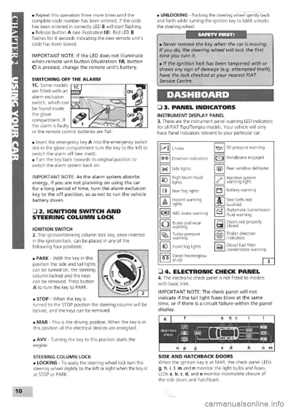
• 3. PANEL INDICATORS
INSTRUMENT DISPLAY PANEL
3. These are the instrument panel warning LED indicators
for all FIAT Tipo/Tempra models. Your vehicle will only
have Panel Indicators relevant to your particular car.
• 4. ELECTRONIC CHECK PANEL
4. The electronic check panel is not fitted to models
with basic trim.
IMPORTANT NOTE: The check panel will not
indicate if the tail light fuses blow at the same
time, or if there is a circuit failure within the panel
display.
SIDE AND HATCHBACK DOORS
When the ignition key is at MAR, the check panel LEDs
g, h, i, I, m and n monitor the light bulbs and fuses.
LEDs a, b, c, d, and e monitor incomplete closure of
the side doors and hatchback.
• Never remove the key when the car is moving.
If you do, the steering wheel will lock the first
time you turn it.
• If the ignition lock has been tampered with or
shows any sign of damage (e.g. attempted theft),
have the lock checked at your nearest FIAT
Service Centre.
M Choke Oil pressure warning
Direction indicators (®) Handbrake engaged
-X: Side lights m Rear window defroster
10 High beam head
lights '•y Injection system warning light
<1* Rear fog lights • Battery warning
A Hazard warning lights A Seat belts not
buckled
m ABS brake warning a Automatic transmission fluid warning
o Brake pad wear warning a Doors not properly closed
Turbo pressure warning Trailer direction indicators
10 Front fog lights a Diesel fuel filter condenstate warning
•515" Diesel heater/glow •515" plugs 3
SWITCHING OFF THE ALARM
1C. Some models
are fitted with an
alarm exclusion
switch, which can
be found inside
the glove
compartment. If
the alarm is faulty
or the remote control batteries are flat:
Page 8 of 171
AIR CONDITIONING (EARLY MODELS)
Air conditioning is an optional extra fitted to some
models of Tipo and Tempra.
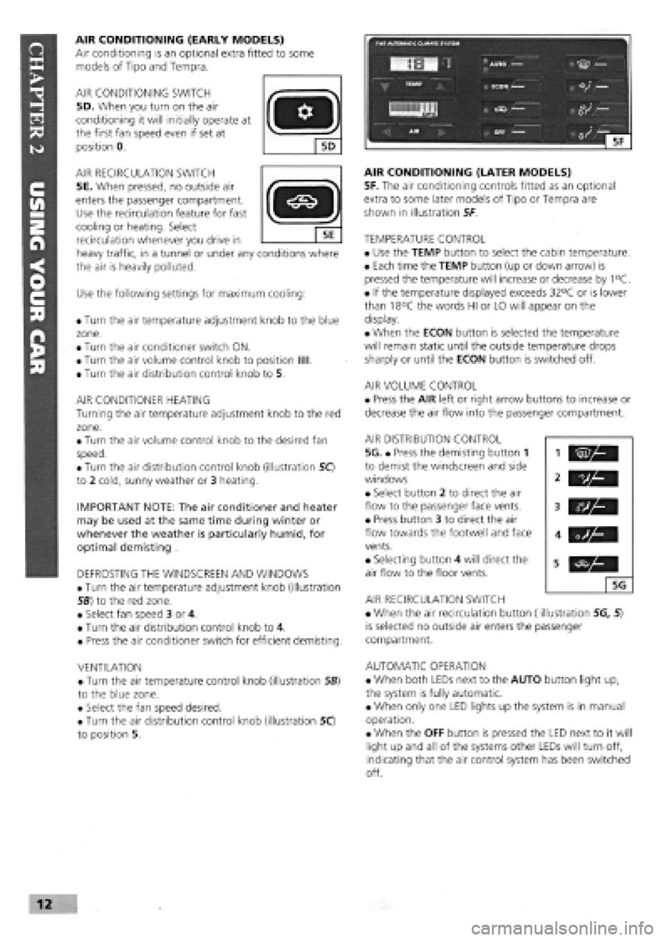
AIR CONDITIONING SWITCH
5D. When you turn on the air
conditioning it will initially operate at
the first fan speed even if set at
position 0.
AIR RECIRCULATION SWITCH
5E. When pressed, no outside air
enters the passenger compartment.
Use the recirculation feature for fast
cooling or heating. Select
recirculation whenever you drive in
heavy traffic, in a tunnel or under any conditions where
the air is heavily polluted.
Use the following settings for maximum cooling:
• Turn the air temperature adjustment knob to the blue
zone.
• Turn the air conditioner switch ON.
• Turn the air volume control knob to position Mil.
• Turn the air distribution control knob to 5.
AIR CONDITIONER HEATING
Turning the air temperature adjustment knob to the red
zone:
• Turn the air volume control knob to the desired fan
speed.
• Turn the air distribution control knob (illustration 50
to 2 cold, sunny weather or 3 heating.
IMPORTANT NOTE: The air conditioner and heater
may be used at the same time during winter or
whenever the weather is particularly humid, for
optimal demisting .
DEFROSTING THE WINDSCREEN AND WINDOWS
• Turn the air temperature adjustment knob (illustration
56) to the red zone.
• Select fan speed 3 or 4.
• Turn the air distribution control knob to 4.
• Press the air conditioner switch for efficient demisting.
VENTILATION
• Turn the air temperature control knob (illustration SB)
to the blue zone.
• Select the fan speed desired.
• Turn the air distribution control knob (illustration 50
to position 5.
AIR CONDITIONING (LATER MODELS)
5F. The air conditioning controls fitted as an optional
extra to some later models of Tipo or Tempra are
shown in illustration 5F
TEMPERATURE CONTROL
• Use the TEMP button to select the cabin temperature.
• Each time the TEMP button (up or down arrow) is
pressed the temperature will increase or decrease by 1°C.
• If the temperature displayed exceeds 32°C or is lower
than 18°C the words HI or LO will appear on the
display.
• When the ECON button is selected the temperature
will remain static until the outside temperature drops
sharply or until the ECON button is switched off.
AIR VOLUME CONTROL
• Press the AIR left or right arrow buttons to increase or
decrease the air flow into the passenger compartment.
AIR DISTRIBUTION CONTROL
5G. • Press the demisting button 1
to demist the windscreen and side
windows.
• Select button 2 to direct the air
flow to the passenger face vents.
• Press button 3 to direct the air
flow towards the footwell and face
vents.
• Selecting button 4 will direct the
air flow to the floor vents.
AIR RECIRCULATION SWITCH
• When the air recirculation button (illustration 5G, 5)
is selected no outside air enters the passenger
compartment.
AUTOMATIC OPERATION
• When both LEDs next to the AUTO button light up,
the system is fully automatic.
• When only one LED lights up the system is in manual
operation.
• When the OFF button is pressed the LED next to it will
light up and all of the systems other LEDs will turn off,
indicating that the air control system has been switched
off.
vh
5G
Page 9 of 171
CONTROLS
• 6. LIGHTS AND INDICATORS
DIRECTION INDICATORS AND REAR FOG LIGHT
SWITCH
The lights operate when the key is at the MAR position.
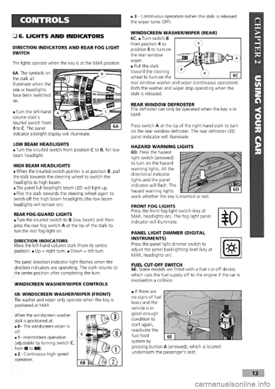
6A. The symbols on
the stalk all
illuminate when the
side or headlights
have been switched
on.
• 3
-
Continuous operation (when the stalk is released
the wiper turns OFF).
WINDSCREEN WASHER/WIPER (REAR)
6C. • Turn switch B
from position 4 to
position 5 to turn on
the rear window
wiper.
• Pull the stalk
toward the steering
wheel to turn on the
rear window washer and wiper (continuous operation).
Both the washer and wiper stop operating when the
stalk is released.
REAR WINDOW DEFROSTER The defroster can only be operated when the key is in
MAR:
LOW BEAM HEADLIGHTS
• Turn the knurled switch from position C to B, for low
beam headlight.
HIGH BEAM HEADLIGHTS
• When the knurled switch pointer is at position B, pull
the stalk towards the steering wheel to switch the
headlights to high beam.
• The panel full headlight beam LED will light up.
• Flick the stalk towards the steering wheel again to
switch off the high beam headlights (the low beam
headlights will remain on).
REAR FOG-GUARD LIGHTS
•
Turn
the knurled switch to B (low beam) and then
press the rear fog switch A at the tip of the stalk to
turn the rear fog-light on.
DIRECTION INDICATORS Move the left-hand column stalk (from its centre
position): • Up = right turn. • Down = left turn.
The panel direction indicator light flashes when the
direction indicators are operating. The stalk returns to
the centre position after completing the turn.
WINDSCREEN WASHER/WIPER CONTROLS
6B: WINDSCREEN WASHER/WIPER (FRONT)
The washer and wiper only operate when the key is
positioned at MAR.
When the windscreen washer
stalk is positioned at:
• 0
-
The windscreen wiper is
off.
•
1 -
Intermittent operation
(adjustable by turning switch C,
from II to III).
• 2
-
Continuous high speed
operation.
Press switch A at the tip of the right-hand stalk to turn
on the rear window defroster. The rear defroster LED
panel indicator will illuminate.
HAZARD WARNING LIGHTS
6D. Press the hazard
light switch (arrowed)
to turn on the hazard
warning lights. All the
directional indicator
lights and the panel
indicator will flash. The
hazard warning lights
work whether the key is inserted or not.
FRONT FOG LIGHTS Press the front fog light switch (key at
MAR, headlights on). The fog light panel
indicator will illuminate.
PANEL LIGHT DIMMER (DIGITAL
INSTRUMENTS)
Press the panel light dimmer switch to
adjust the panel backlighting level (key at
MAR, headlights on).
FUEL CUT-OFF SWITCH
6E. Some models are fitted with a fuel cut-off device,
which cuts the fuel supply off to the engine if the car is
involved in a collision.
• If there are
no signs of fuel
leaks and the
vehicle is in
good enough
condition to
start again,
reactivate the
fuel feed
system by
pressing button A (arrowed), which is located
underneath the passenger's seat.
• Turn the left-hand
column stalk's
knurled switch from
0 to C. The panel
indicator sidelight display will illuminate.
Page 10 of 171
• 9. DOOR MIRROR ADJUSTMENT
• 7. STEERING WHEEL
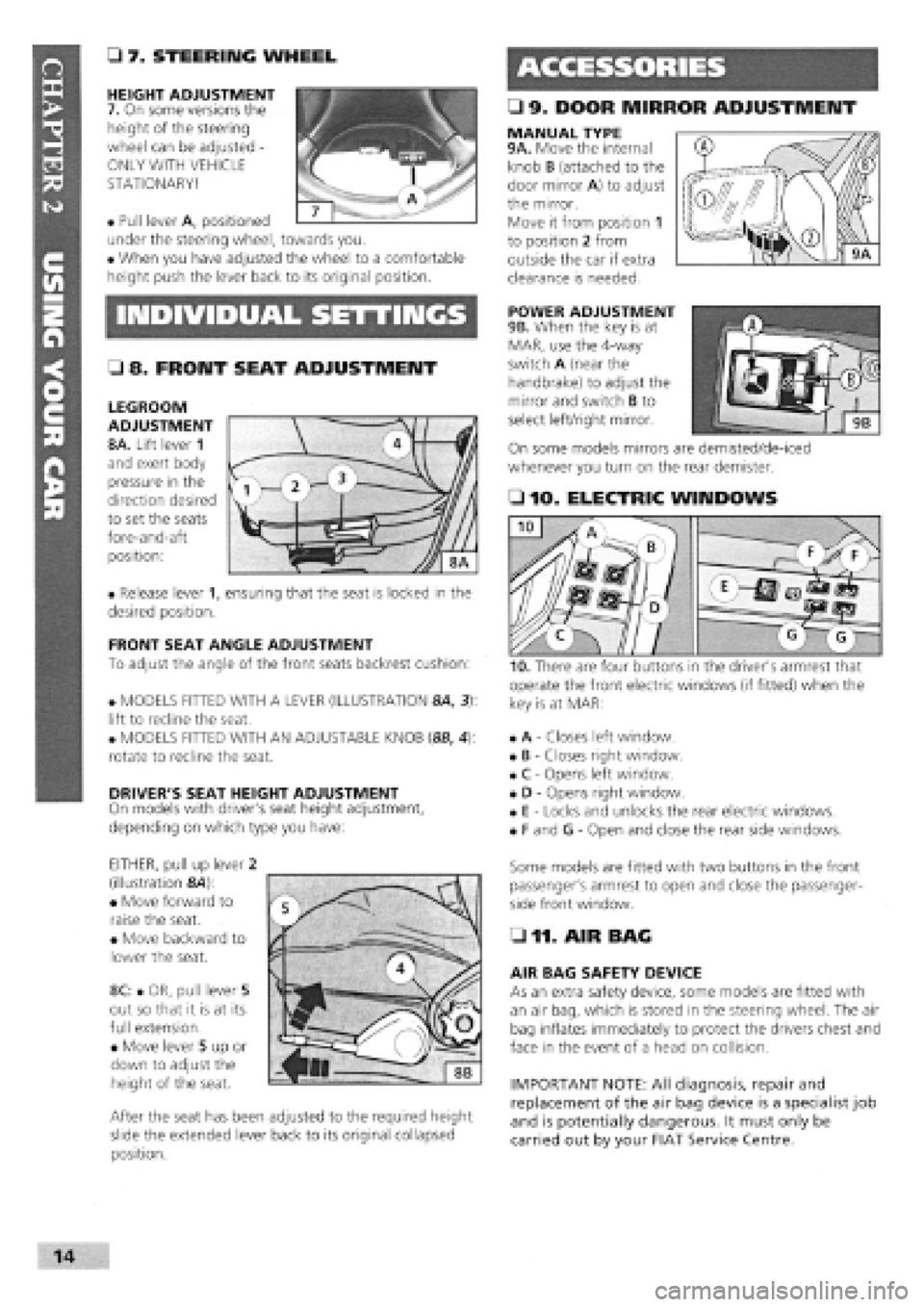
HEIGHT ADJUSTMENT
7. On some versions the
height of the steering
wheel can be adjusted -
ONLY WITH VEHICLE
STATIONARY!
• Pull lever A, positioned
under the steering wheel, towards you.
• When you have adjusted the wheel to a comfortable
height push the lever back to its original position.
MANUAL TYPE 9A. Move the internal
knob B (attached to the
door mirror A) to adjust
the mirror.
Move it from position 1
to position 2 from
outside the car if extra
clearance is needed.
INDIVIDUAL SETTINGS POWER ADJUSTMENT
9B. When the key is at
MAR, use the 4-way
switch A (near the
handbrake) to adjust the
mirror and switch B to
select left/right mirror.
On some models mirrors are demisted/de-iced
whenever you turn on the rear demister.
• 8. FRONT SEAT ADJUSTMENT
LEGROOM
ADJUSTMENT
8A. Lift lever 1
and exert body
pressure in the
direction desired
to set the seats
fore-and-aft
position:
• Release lever 1, ensuring that the seat is locked in the
desired position.
FRONT SEAT ANGLE ADJUSTMENT
To adjust the angle of the front seats backrest cushion:
• MODELS FITTED WITH A LEVER (ILLUSTRATION 8A, 3):
lift to recline the seat.
• MODELS FITTED WITH AN ADJUSTABLE KNOB (8B, 4):
rotate to recline the seat.
DRIVER'S SEAT HEIGHT ADJUSTMENT
On models with driver's seat height adjustment,
depending on which type you have:
EITHER, pull up lever 2
(illustration &4):
• Move forward to
raise the seat.
• Move backward to
lower the seat.
8C: • OR, pull lever 5
out so that it is at its
full extension.
• Move lever 5 up or
down to adjust the
height of the seat.
After the seat has been adjusted to the required height
slide the extended lever back to its original collapsed
position.
• 10. ELECTRIC WINDOWS
operate the front electric windows (if fitted) when the
key is at MAR:
• A
-
Closes left window.
• B
-
Closes right window.
• C
-
Opens left window.
• D
-
Opens right window.
• E
-
Locks and unlocks the rear electric windows.
• F and G
-
Open and close the rear side windows.
Some models are fitted with two buttons in the front
passenger's armrest to open and close the passenger-
side front window.
• 11. AIR BAG
AIR BAG SAFETY DEVICE
As an extra safety device, some models are fitted with
an air bag, which is stored in the steering wheel. The air
bag inflates immediately to protect the drivers chest and
face in the event of a head on collision.
IMPORTANT NOTE: All diagnosis, repair and
replacement of the air bag device is a specialist job
and is potentially dangerous. It must only be
carried out by your FIAT Service Centre.
I
Page 11 of 171
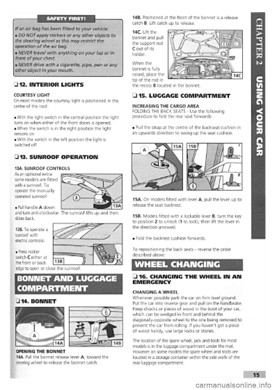
SAFETY FIRST!
If an air bag has been fitted to your vehicle:
• DO NOT apply stickers or any other objects to
the steering wheel as this may restrict the
operation of the air bag.
• NEVER travel with anything on your lap or in
front of your chest
• NEVER drive with a cigarette, pipe, pen or any
other object in your mouth.
• 12. INTERIOR LIGHTS
COURTESY LIGHT
On most models the courtesy light is positioned in the
centre of the roof.
• With the light switch in the central position the light
turns on when either of the front doors is opened.
• When the switch is in the right position the light
remains on.
• With the switch in the left position the light is
switched off.
• 13. SUNROOF OPERATION
14B. Positioned at the front of the bonnet is a release
catch B. Lift catch up to release.
14C. Lift the
bonnet and pull
the support rod
C out of its
holder.
When the
• 15. LUGGAGE COMPARTMENT
INCREASING THE CARGO AREA
FOLDING THE BACK SEATS
-
Use the following
procedure to fold the rear seat forwards:
• Pull the strap at the centre of the backseat cushion in
an upwards direction to swing up the seat cushion.
15A. On models fitted with lever A, pull the lever up to
release the seat backrest.
15B. Models fitted with a lockable lever B, turn the key
to position 2 to unlock (1 to lock), then lift the lever in
the direction arrowed.
• Fold the backrest cushion forwards.
BONNET AND LUGGAGE
L 2 . fj§
• 14 .BONNET
OPENING THE BONNET
14A. Pull the bonnet release lever A, toward the
steering wheel to release the bonnet catch.
To repositioning the back seats
-
reverse the order
described above.
WHEEL CHANGING
• 16. CHANGING THE WHEEL IN AN
EMERGENCY
CHANGING A WHEEL
Whenever possible park the car on firm level ground.
Put the car into reverse gear and pull on the handbrake.
Keep chocks or pieces of wood in the boot of your car,
which can be wedged in front and behind the
diagonally-opposite wheel to the one being removed to
prevent the car from rolling. If you haven't got a piece
of wood handy, use large rocks or stones.
The location of the spare wheel, jack and tools for most
models is in the luggage compartment under the mat.
However on some models the spare wheel and tools are
located in a storage container within the side walls of the
rear luggage compartment.
bonnet is fully
raised, place the
tip of the rod in
the recess B located in the bonnet.
• Pull handle A down
and turn anti-clockwise,
slides back.
13B. To operate a
sunroof with
electric controls:
13A. SUNROOF CONTROLS
As an optional extra
some models are fitted
with a sunroof. To
operate the manually
operated sunroof:
The sunroof lifts up and then
• Press rocker
switch C either at
the front or back
edge to open or close the sunroof.
Z3
Page 15 of 171
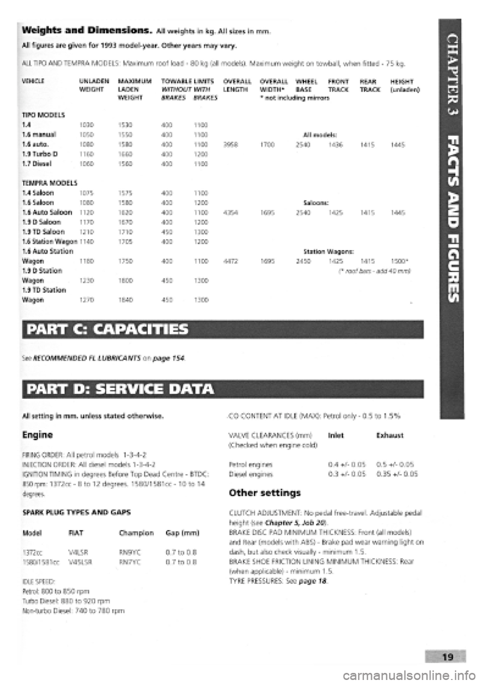
Weights and Dimensions. All weights in kg. All sizes in mm.
All figures are given for 1993 model-year. Other years may vary.
ALL TIPO AND TEMPRA MODELS: Maximum roof load
-
80 kg (all models). Maximum weight on towball, when fitted - 75 kg.
VEHICLE
TIPO MODELS
1.4
1.6 manual
1.6 auto.
1.9 Turbo D
1.7 Diesel
UNLADEN WEIGHT
1030
1050
1080
1160
1060
MAXIMUM
LADEN WEIGHT
1530
1550
1580
1660
1560
TOWABLE LIMITS WITHOUT WITH BRAKES BRAKES
400
400
400
400
400
1100
1100
1100
1200
1100
OVERALL LENGTH
3958
OVERALL WHEEL FRONT WIDTH* BASE TRACK * not including mirrors
1700
All models:
2540 1436
REAR TRACK
1415
HEIGHT (unladen)
1445
TEMPRA MODELS
1.4 Saloon 1075 1575 400 1100
1.6 Saloon 1080 1580 400 1200 Saloons:
1.6 Auto Saloon 1120 1620 400 1100 4354 1695 2540 1425 1415 1445
1.9 D Saloon 1170 1670 400 1200
1.9 TD Saloon 1210 1710 450 1300
1.6 Station Wagon 1140 1705 400 1200
1.6 Auto Station Station Wagons:
Wagon 1180 1750 400 1100 4472 1695 2450 1425 1415 1500*
1.9 D Station (* roof bars - add 40 mm)
Wagon 1230 1800 450 1300
1.9 TD Station
Wagon 1270 1840 450 1300
PART C: CAPACITIES
See RECOMMENDED EL LUBRICANTS on page 154.
PART D: SERVICE DATA
All setting in mm. unless stated otherwise.
Engine
FIRING ORDER: All petrol models 1-3-4-2
INJECTION ORDER: All diesel models 1-3-4-2
IGNITION TIMING in degrees Before Top Dead Centre
-
BTDC:
850 rpm: 1372cc-8to 12 degrees. 1580/1581cc- 10 to 14
degrees.
CO CONTENT AT IDLE (MAX): Petrol only
-
0.5 to 1.5%
Exhaust VALVE CLEARANCES (mm) Inlet
(Checked when engine cold)
Petrol engines
Diesel engines
Other settings
0.4
+/-
0.05
0.3
+/-
0.05
0.5
+/-
0.05
0.35
+/-
0.05
SPARK PLUG TYPES AND GAPS
Model FIAT
1372cc V4LSR
1580/1581
cc V45LSR
Champion Gap (mm)
RN9YC
RN7YC
IDLE SPEED:
Petrol: 800 to 850 rpm
Turbo Diesel: 880 to 920 rpm
Non-turbo Diesel: 740 to 780 rpm
0.7 to 0.8
0.7 to 0.8
CLUTCH ADJUSTMENT: No pedal free-travel. Adjustable pedal
height (see Chapter 5, Job 20).
BRAKE DISC PAD MINIMUM THICKNESS: Front (all models)
and Rear (models with ABS)
-
Brake pad wear warning light on
dash, but also check visually
-
minimum 1.5.
BRAKE SHOE FRICTION LINING MINIMUM THICKNESS: Rear
(when applicable)
-
minimum 1.5.
TYRE PRESSURES: See page 18
Page 24 of 171
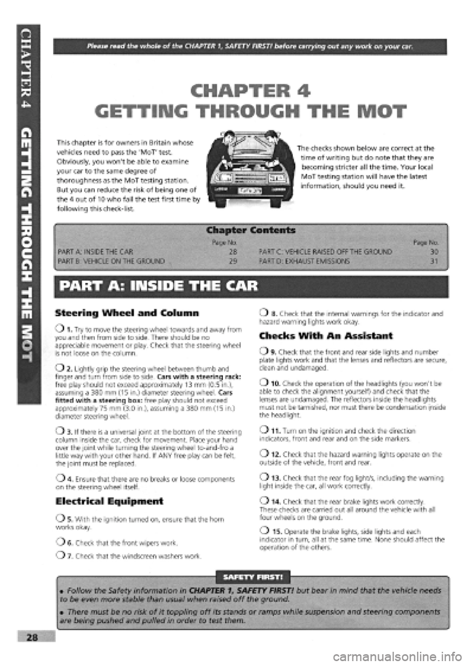
Please read the whole of the CHAPTER 1, SAFETY FIRST! before carrying out any work on your car.
fUADTCSA I En Hr
GETTIIMG THROUGH THE MOT
This chapter is for owners in Britain whose
vehicles need to pass the 'MoT' test.
Obviously, you won't be able to examine
your car to the same degree of
thoroughness as the MoT testing station.
But you can reduce the risk of being one of
the 4 out of 10 who fail the test first time by
following this check-list.
iMFTri
The checks shown below are correct at the
time of writing but do note that they are
becoming stricter all the time. Your local
MoT testing station will have the latest
information, should you need it.
1 p Chapter Contents -
Page No. Page No.
PART A: INSIDE THE CAR 28 PART C: VEHICLE RAISED OFF THE GROUND 30
PART B: VEHICLE ON THE GROUND 29 PART D: EXHAUST EMISSIONS 31
PART A: INSIDE THE CAR
Steering Wheel and Column
O 1. Try to move the steering wheel towards and away from you and then from side to side. There should be no appreciable movement or play. Check that the steering wheel is not loose on the column.
02 . Lightly grip the steering wheel between thumb and finger and turn from side to side. Cars with a steering rack: free play should not exceed approximately 13 mm (0.5 in.), assuming a 380 mm (15 in.) diameter steering wheel. Cars fitted with a steering box: free play should not exceed approximately 75 mm (3.0 in.), assuming a 380 mm (15 in.) diameter steering wheel.
Ob . If there is a universal joint at the bottom of the steering column inside the car, check for movement. Place your hand over the joint while turning the steering wheel to-and-fro a little way with your other hand. If ANY free play can be felt, the joint must be replaced.
04. Ensure that there are no breaks or loose components
on the steering wheel itself.
Electrical Equipment
OS . With the ignition turned on, ensure that the horn works okay.
OE . Check that the front wipers work.
07 . Check that the windscreen washers work.
o 8. Check that the internal warnings for the indicator and hazard warning lights work okay.
Checks With An Assistant
O9 . Check that the front and rear side lights and number plate lights work and that the lenses and reflectors are secure, clean and undamaged.
o 10. Check the operation of the headlights (you won't be able to check the alignment yourself) and check that the lenses are undamaged. The reflectors inside the headlights must not be tarnished, nor must there be condensation inside the headlight.
o 11. Turn on the ignition and check the direction
indicators, front and rear and on the side markers.
o 12. Check that the hazard warning lights operate on the
outside of the vehicle, front and rear.
o 13. Check that the rear fog light/s, including the warning
light inside the car, all work correctly.
o 14. Check that the rear brake lights work correctly. These checks are carried out all around the vehicle with all four wheels on the ground.
o 15. Operate the brake lights, side lights and each indicator in turn, all at the same time. None should affect the operation of the others.
SAFETY FIRST!
• Follow the Safety information in CHAPTER 1, SAFETY FIRST! but bear in mind that the vehicle needs
to be even more stable than usual when raised off the ground.
• There must be no risk of it toppling off its stands or ramps while suspension and steering components
are being pushed and pulled in order to test them.
Page 30 of 171
PART G: BRAKING SYSTEM
Job 49. Check front brakes
Job 50. Check rear brakes
Job 51. Check/adjust handbrake
Job 52. Check brake pipes
Job 53. Change brake hydraulic fluid
SERVICE INTERVALS
C
C
C
C
E
Job 56. Check seat and seat belt mountings C
Job 57. Check headlight alignment C
Job 58. Check underbody C
Job 59. Check spare tyre B
Job 60. Change pollen filter C
Job 61. Replace airbag gas generator 10 years
PART I: ROAD TEST
PART H: BODYWORK & INTERIOR
Job 54. Lubricate hinges and locks
Job 55. Check windscreen
Job 62. Road test and specialist check. AFTER EVERY
SERVICE
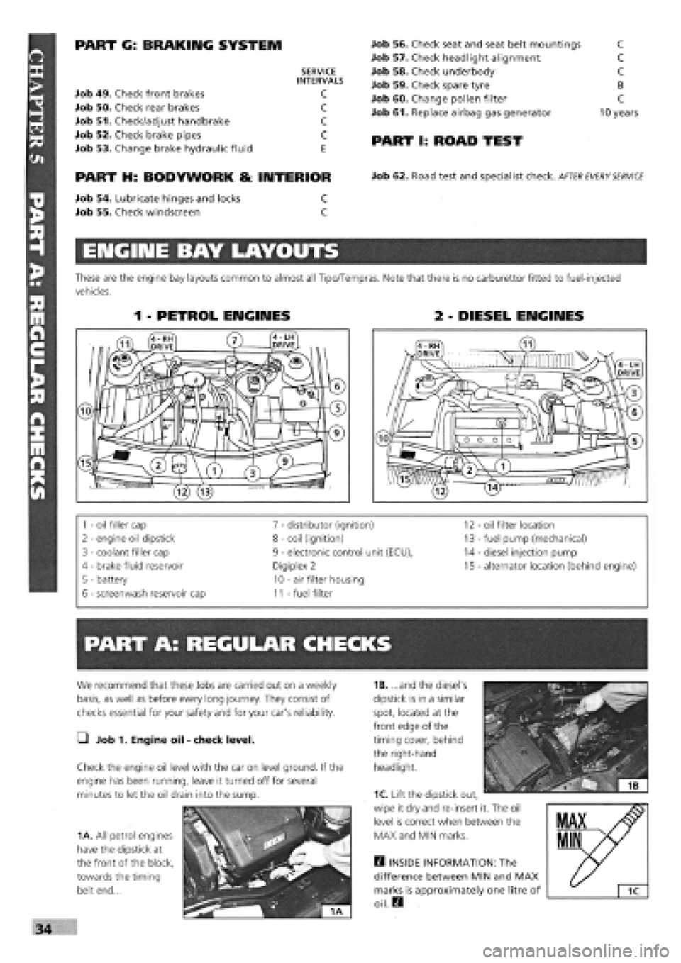
ENGINE BAY LAYOUTS
These are the engine bay layouts common to almost all Tipo/Tempras. Note that there is no carburettor fitted to fuel-injected
vehicles.
1 - PETROL ENGINES 2 - DIESEL ENGINES
1
-
oil filler cap 7
-
distributor (ignition) 12 - oil filter location
2
-
engine oil dipstick 8
-
coil (ignition) 13
-
fuel pump (mechanical)
3
-
coolant filler cap 9
-
electronic control unit (ECU), 14
-
diesel injection pump
4 - brake fluid reservoir Digiplex 2 15
-
alternator location (behind engine)
5 - battery 10
-
air filter housing
6
-
screenwash reservoir cap 11
-
fuel filter
PART A: REGULAR CHECKS
1B. ...and the diesel's
dipstick is in a similar
spot, located at the
front edge of the
timing cover, behind
the right-hand
headlight.
Q INSIDE INFORMATION: The
difference between MIN and MAX
marks is approximately one litre of
oil. Q
We recommend that these Jobs are carried out on a weekly
basis, as well as before every long journey. They consist of
checks essential for your safety and for your car's reliability.
• Job 1. Engine oil
-
check level.
Check the engine oil level with the car on level ground. If the
engine has been running, leave it turned off for several
minutes to let the oil drain into the sump.
1A. All petrol engines
have the dipstick at
the front of the block,
towards the timing
belt end...
1C. Lift the dipstick out,
wipe it dry and re-insert it. The oil
level is correct when between the
MAX and MIN marks.
Page 33 of 171
• Whenever a light fails to
work, check its fuse before
replacing the bulb.
• A blown bulb often causes a fuse to 'go' in
sympathy.
hands, looking and feeling for any bulges, tears or splits in the
tyre walls, especially the inner sidewalls. (See Job 59 for spare
tyre checks.)
H INSIDE INFORMATION: In time, rubber deteriorates,
increasing the risk of a blow-out. Keep your eye on the
sidewalls of older tyres. If you see any cracking, splits or
other damage scrap the tyre. If you're not sure, consult
your FIAT dealer or tyre specialist. Q
_) Job 7. Check lights/change bulbs.
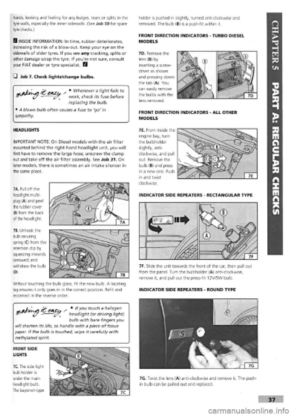
7A. Pull off the
headlight multi-
plug (A) and peel
the rubber cover
(B) from the back
of the headlight.
7B. Unhook the
bulb securing
spring (C) from the
retention clip by
squeezing inwards
(arrowed) and
withdraw the bulb
(D).
Without touching the bulb glass, fit the new bulb. A locating
tag ensures it only goes in in the correct position. Refit and
reconnect in the reverse order.
HEADLIGHTS
IMPORTANT NOTE: On Diesel models with the air filter
mounted behind the right-hand headlight unit, you will
first have to remove the large hose, unscrew the clamp
nut and take off the air filter assembly. See Job 31. On
later models, there is sometimes an air intake silencer in
the same place.
7F. Slide the unit towards the front of the car, then pull out
from the panel. Turn the bulbholder (A) anti-clockwise,
remove it, and pull out the press-fit 12V/5W bulb.
INDICATOR SIDE REPEATERS
-
ROUND TYPE
holder is pushed in slightly, turned anti-clockwise and
removed. The bulb (B) is a push-fit within it.
FRONT DIRECTION INDICATORS
-
TURBO DIESEL
MODELS
7D. Remove the
lens (B) by
inserting a screw-
driver as shown
and pressing down
the tab (A). You
can easily remove
the bulbs with the
lens removed.
FRONT DIRECTION INDICATORS
-
ALL OTHER
MODELS
7E. From inside the
engine bay, turn
the bulbholder
slightly, anti-
clockwise, and pull
out. Remove the
bulb (B) and press
in a new one. Push
in and twist
clockwise.
INDICATOR SIDE REPEATERS
-
RECTANGULAR TYPE
CAS / * touc^ a halogen
• headlight (or driving light)
bulb with bare fingers you
will
shorten its life, so handle with a piece of
tissue
paper. If the bulb is touched, wipe it carefully with
methylated spirit.
FRONT SIDE
LIGHTS
7C.
The side light
bulb holder is
under the main
headlight bulb.
The bayonet-type
7G. Twist the lens (A) anti-clockwise and remove it. The push-
in bulb can be pulled out and replaced.
Page 35 of 171
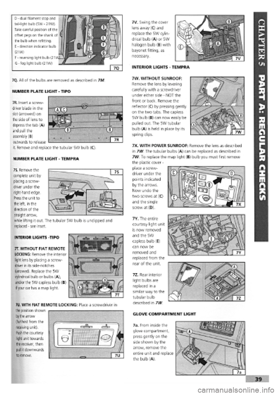
D
-
dual filament stop and
tail-light bulb (5W
-
21W).
Take careful position of the
offset pegs on the shank of
the bulb when refitting.
E
-
direction indicator bulb
(21W)
F
-
reversing light bulb (21
G-fog light bulb (21W)
7V. Swing the cover
lens away (C) and
replace the 5W cylin-
drical bulb (A) or 5W
halogen bulb (B) with
bayonet fitting, as
necessary.
INTERIOR LIGHTS
-
TEMPRA
7Q. All of the bulbs are removed as described in 7M
NUMBER PLATE LIGHT
-
TIPO
NUMBER PLATE LIGHT
-
TEMPRA
7W. WITHOUT SUNROOF:
Remove the lens by levering
carefully with a screwdriver
under either side
-
NOT the
front or back. Remove the
reflector (C) by pressing gently
on the two tabs. The capless
5W bulb (B) can now easily be
pulled out. The 5W tubular
bulb (A) is held in place by its
spring clips.
7X. WITH POWER SUNROOF: Remove the lens as described
in 7W. The tubular bulbs (A) can be replaced as described in
7W. To replace the map light (B) bulb you must first remove
the plastic cover
-
place a screw-
driver under the
points indicated
by the arrows.
Now undo the
two screws at (C)
and the single
screw at (D).
7Y. The entire
courtesy light unit
is now removed
and the 5W
capless bulb (E)
can now be
removed and
replaced from the
rear of the unit.
7Z. Rear interior
light bulbs are
replaced in a
similar way to the
tubular bulb
described in 7W
GLOVE COMPARTMENT LIGHT
7a. From inside the
glove compartment,
press gently on the
side shown by the
arrow, remove the
entire unit and replace
the bulb (A).
INTERIOR LIGHTS -TIPO
7T.
WITHOUT FIAT REMOTE
LOCKING: Remove the interior
light
lens
by placing a screw-
driver
in
its side-notches
(arrowed). Replace the 5W
cylindrical bulb or bulbs (A),
and/or
the 5W capless bulb (B)
if your
car has a map light.
7U.
WITH FIAT REMOTE LOCKING: Place a screwdriver in
the position shown
by the
arrow
(furthest
from
the
receiving unit).
Push
the courtesy
light
unit towards
the receiver, then
pull
it downwards
to
remove.
7R. Insert a screw-
driver blade in the
slot (arrowed) on
the side of lens to
depress the tab (A)
and pull the
assembly (B)
outwards to release
it. Remove and replace the tubular 5W bulb (C).
7S. Remove the
complete unit by
placing a screw-
driver under the
right-hand edge.
Press
the unit to
the left, in the
direction of the
straight arrow,
while lifting it out. The tubular 5W bulb is undipped and
replaced
-
see inset.