heater FIAT TEMPRA 1988 Service And Repair Manual
[x] Cancel search | Manufacturer: FIAT, Model Year: 1988, Model line: TEMPRA, Model: FIAT TEMPRA 1988Pages: 171, PDF Size: 18.05 MB
Page 6 of 171
• Repeat this operation three more times until the
complete code number has been entered, if the code
has been entered in correctly LED B will start flashing.
• Release button A (see illustration
1B).
Red LED B
flashes for 8 seconds indicating the new remote unit's
code has been stored.
IMPORTANT NOTE: If the LED does not illuminate
when remote unit button (illustration 1B, button
O is pressed, change the remote unit's battery.
• Insert the emergency key A into the emergency switch
slot in the glove compartment turn the key to the left to
switch the alarm off (see inset).
• Turn the key back towards its original position to
switch the alarm system back on.
IMPORTANT NOTE: As the alarm system absorbs
energy, if you are not planning on using the car
for a long period of time, turn the alarm exclusion
key to the off position, so as not to run the vehicle
battery down.
• 2. IGNITION SWITCH AND
STEERING COLUMN LOCK
IGNITION SWITCH
2. The ignition/steering column lock key, once inserted
in the ignition lock, can be placed in any of the
following four positions:
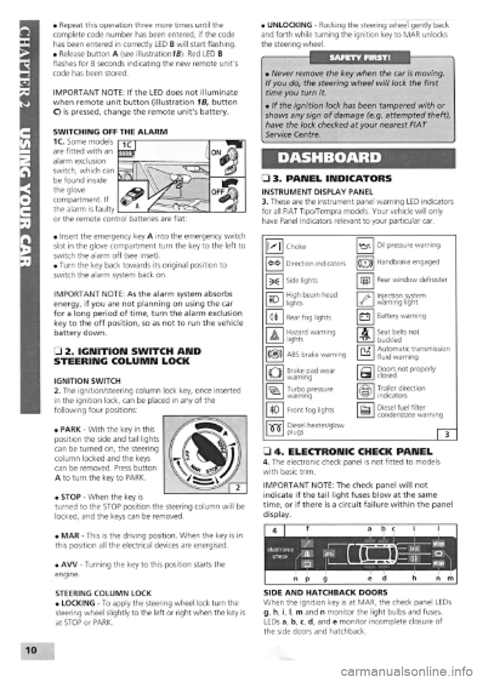
• PARK
-
With the key in this
position the side and tail lights
can be turned on, the steering
column locked and the keys
can be removed. Press button
A to turn the key to PARK.
• STOP
-
When the key is
turned to the STOP position the steering column will be
locked, and the keys can be removed.
• MAR
-
This is the driving position. When the key is in
this position all the electrical devices are energised.
• AW
-
Turning the key to this position starts the
engine.
STEERING COLUMN LOCK
• LOCKING
-
To apply the steering wheel lock turn the
steering wheel slightly to the left or right when the key is
at STOP or PARK.
• UNLOCKING
-
Rocking the steering wheel gently back
and forth while turning the ignition key to MAR unlocks
the steering wheel.
• 3. PANEL INDICATORS
INSTRUMENT DISPLAY PANEL
3. These are the instrument panel warning LED indicators
for all FIAT Tipo/Tempra models. Your vehicle will only
have Panel Indicators relevant to your particular car.
• 4. ELECTRONIC CHECK PANEL
4. The electronic check panel is not fitted to models
with basic trim.
IMPORTANT NOTE: The check panel will not
indicate if the tail light fuses blow at the same
time, or if there is a circuit failure within the panel
display.
SIDE AND HATCHBACK DOORS
When the ignition key is at MAR, the check panel LEDs
g, h, i, I, m and n monitor the light bulbs and fuses.
LEDs a, b, c, d, and e monitor incomplete closure of
the side doors and hatchback.
• Never remove the key when the car is moving.
If you do, the steering wheel will lock the first
time you turn it.
• If the ignition lock has been tampered with or
shows any sign of damage (e.g. attempted theft),
have the lock checked at your nearest FIAT
Service Centre.
M Choke Oil pressure warning
Direction indicators (®) Handbrake engaged
-X: Side lights m Rear window defroster
10 High beam head
lights '•y Injection system warning light
<1* Rear fog lights • Battery warning
A Hazard warning lights A Seat belts not
buckled
m ABS brake warning a Automatic transmission fluid warning
o Brake pad wear warning a Doors not properly closed
Turbo pressure warning Trailer direction indicators
10 Front fog lights a Diesel fuel filter condenstate warning
•515" Diesel heater/glow •515" plugs 3
SWITCHING OFF THE ALARM
1C. Some models
are fitted with an
alarm exclusion
switch, which can
be found inside
the glove
compartment. If
the alarm is faulty
or the remote control batteries are flat:
Page 8 of 171
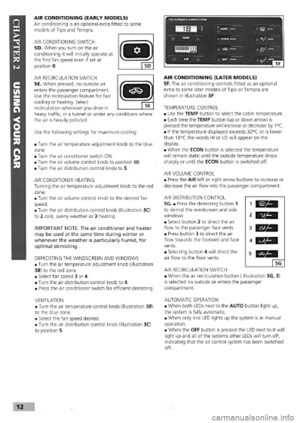
AIR CONDITIONING (EARLY MODELS)
Air conditioning is an optional extra fitted to some
models of Tipo and Tempra.
AIR CONDITIONING SWITCH
5D. When you turn on the air
conditioning it will initially operate at
the first fan speed even if set at
position 0.
AIR RECIRCULATION SWITCH
5E. When pressed, no outside air
enters the passenger compartment.
Use the recirculation feature for fast
cooling or heating. Select
recirculation whenever you drive in
heavy traffic, in a tunnel or under any conditions where
the air is heavily polluted.
Use the following settings for maximum cooling:
• Turn the air temperature adjustment knob to the blue
zone.
• Turn the air conditioner switch ON.
• Turn the air volume control knob to position Mil.
• Turn the air distribution control knob to 5.
AIR CONDITIONER HEATING
Turning the air temperature adjustment knob to the red
zone:
• Turn the air volume control knob to the desired fan
speed.
• Turn the air distribution control knob (illustration 50
to 2 cold, sunny weather or 3 heating.
IMPORTANT NOTE: The air conditioner and heater
may be used at the same time during winter or
whenever the weather is particularly humid, for
optimal demisting .
DEFROSTING THE WINDSCREEN AND WINDOWS
• Turn the air temperature adjustment knob (illustration
56) to the red zone.
• Select fan speed 3 or 4.
• Turn the air distribution control knob to 4.
• Press the air conditioner switch for efficient demisting.
VENTILATION
• Turn the air temperature control knob (illustration SB)
to the blue zone.
• Select the fan speed desired.
• Turn the air distribution control knob (illustration 50
to position 5.
AIR CONDITIONING (LATER MODELS)
5F. The air conditioning controls fitted as an optional
extra to some later models of Tipo or Tempra are
shown in illustration 5F
TEMPERATURE CONTROL
• Use the TEMP button to select the cabin temperature.
• Each time the TEMP button (up or down arrow) is
pressed the temperature will increase or decrease by 1°C.
• If the temperature displayed exceeds 32°C or is lower
than 18°C the words HI or LO will appear on the
display.
• When the ECON button is selected the temperature
will remain static until the outside temperature drops
sharply or until the ECON button is switched off.
AIR VOLUME CONTROL
• Press the AIR left or right arrow buttons to increase or
decrease the air flow into the passenger compartment.
AIR DISTRIBUTION CONTROL
5G. • Press the demisting button 1
to demist the windscreen and side
windows.
• Select button 2 to direct the air
flow to the passenger face vents.
• Press button 3 to direct the air
flow towards the footwell and face
vents.
• Selecting button 4 will direct the
air flow to the floor vents.
AIR RECIRCULATION SWITCH
• When the air recirculation button (illustration 5G, 5)
is selected no outside air enters the passenger
compartment.
AUTOMATIC OPERATION
• When both LEDs next to the AUTO button light up,
the system is fully automatic.
• When only one LED lights up the system is in manual
operation.
• When the OFF button is pressed the LED next to it will
light up and all of the systems other LEDs will turn off,
indicating that the air control system has been switched
off.
vh
5G
Page 21 of 171
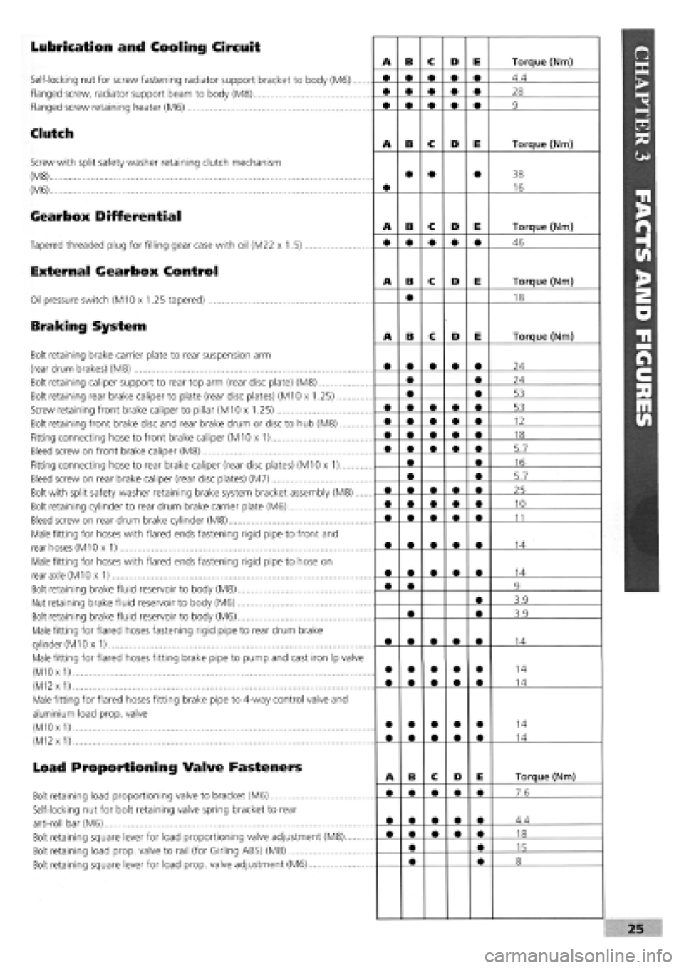
Lubrication and Cooling Circuit
Self-locking nut for screw fastening radiator support bracket to body (M6)....
Flanged screw, radiator support beam to body (M8)
Flanged screw retaining heater (M6)
Clutch
Screw with split safety washer retaining clutch mechanism
(M8)
(M6)
Gearbox Differential
Tapered threaded plug for filling gear case with oil (M22 x 1.5)
External Gearbox Control
Oil pressure switch (M10 x 1.25 tapered)
Braking System
Bolt retaining brake carrier plate to rear suspension arm
(rear drum brakes) (M8)
Bolt retaining caliper support to rear top arm (rear disc plate) (M8)
Bolt retaining rear brake caliper to plate (rear disc plates) (M10 x 1.25)
Screw retaining front brake caliper to pillar (M10 x 1.25)
Bolt retaining front brake disc and rear brake drum or disc to hub (M8)
Fitting connecting hose to front brake caliper (M10 x 1)
Bleed screw on front brake caliper (M8)
Fitting connecting hose to rear brake caliper (rear disc plates) (M10 x 1)
Bleed screw on rear brake caliper (rear disc plates) (M7)
Bolt with split safety washer retaining brake system bracket assembly (M8)....
Bolt retaining cylinder to rear drum brake carrier plate (M6)
Bleed screw on rear drum brake cylinder (M8)
Male fitting for hoses with flared ends fastening rigid pipe to front and
rear hoses (M10 x 1)
Male fitting for hoses with flared ends fastening rigid pipe to hose on
rear axle (M10 x 1)
Bolt retaining brake fluid reservoir to body (M8)
Nut retaining brake fluid reservoir to body (M6)
Bolt retaining brake fluid reservoir to body (M6)
Male fitting for flared hoses fastening rigid pipe to rear drum brake
cylinder
(M1
Ox 1)
Male fitting for flared hoses fitting brake pipe to pump and cast iron Ip valve
(M10
x
1)
(M12
x
1)
Male fitting for flared hoses fitting brake pipe to 4-way control valve and
aluminium load prop, valve
(M10 x
1)
(M12
x
1)
Load Proportioning Valve Fasteners
Bolt retaining load proportioning valve to bracket (M6)
Self-locking nut for bolt retaining valve spring bracket to rear
anti-roll bar (M6)
Bolt retaining square lever for load proportioning valve adjustment (M8)
Bolt retaining load prop, valve to rail (for Girling ABS) (M8)
Bolt retaining square lever for load prop, valve adjustment (M6)
Page 36 of 171
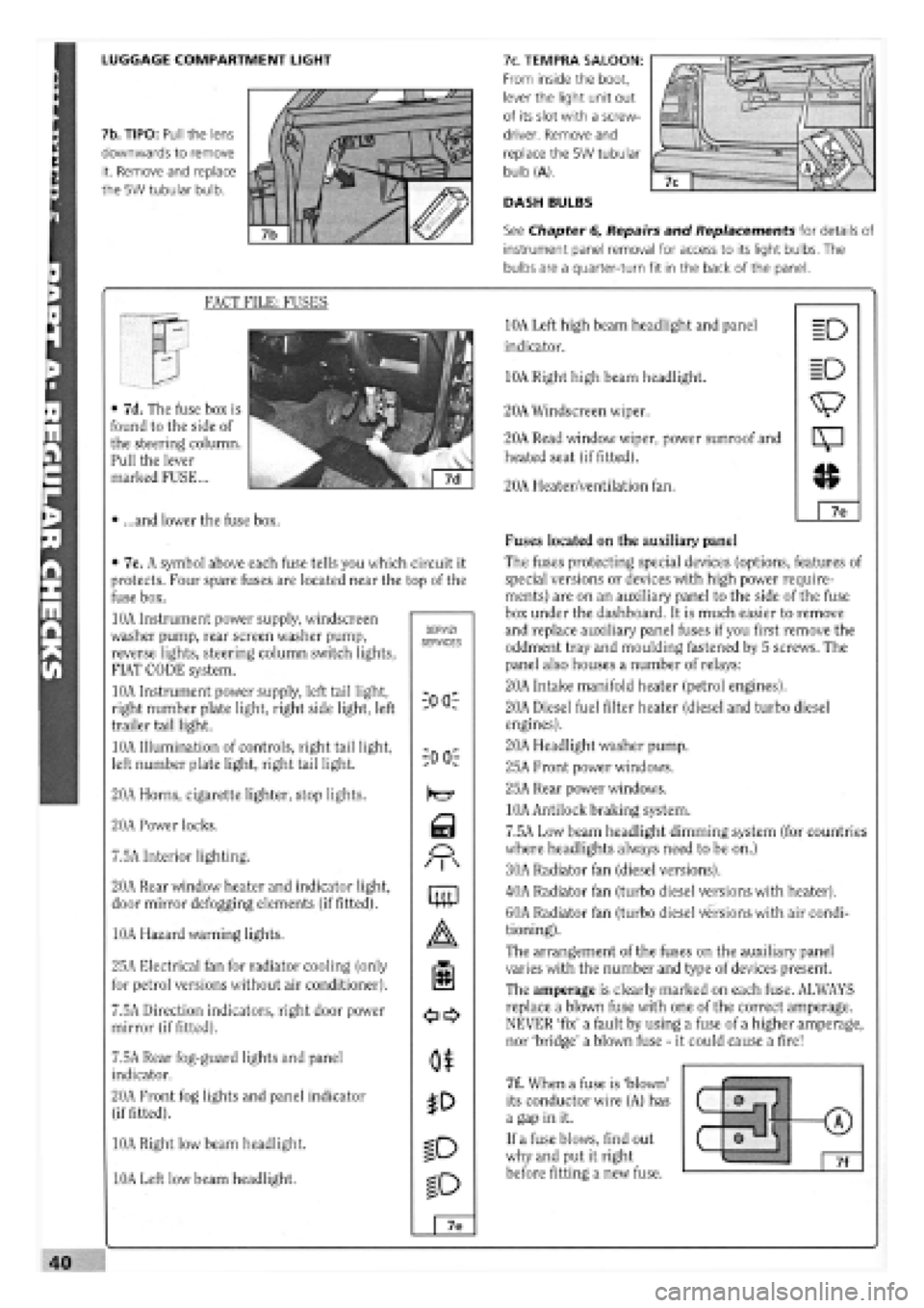
LUGGAGE COMPARTMENT LIGHT
7b. TIPO: Pull the lens
downwards to remove
it. Remove and replace
the 5W tubular bulb.
7c. TEMPRA SALOON:
From inside the boot,
lever the light unit out
of its slot with a screw-
driver. Remove and
replace the 5W tubular
bulb (A).
DASH BULBS
See Chapter 6, Repairs and Replacements for details of
instrument panel removal for access to its light bulbs. The
bulbs are a quarter-turn fit in the back of the panel.
FACT FILE: FUSES
• 7d. The fuse box is
found to the side of
the steering column.
Pull the lever
marked FUSE...
• ...and lower the fuse box.
• 7e. A symbol above each fuse tells you which circuit it
protects. Four spare fuses are located near the top of the
fuse box.
10A Instrument power supply, windscreen
washer pump, rear screen washer pump,
reverse lights, steering column switch lights,
FIAT CODE system.
10A Instrument power supply, left tail light,
right number plate light, right side light, left
trailer tail light.
10A Illumination of controls, right tail light,
left number plate light, right tail light.
20A Horns, cigarette lighter, stop lights.
20A Power locks.
7.5A Interior lighting.
20A Rear window heater and indicator light,
door mirror defogging elements (if fitted).
10A Hazard warning lights.
25A Electrical fan for radiator cooling (only
for petrol versions without air conditioner).
7.5A Direction indicators, right door power
mirror (if fitted).
7.5A Rear fog-guard lights and panel
indicator.
20A Front fog lights and panel indicator
(if fitted).
10A Right low beam headlight.
10A Left low beam headlight.
SERVIZI SERVICES
iOO:
-00 r
Q
M
mp
o$
ID
ID
7e
10A Left high beam headlight and panel
indicator.
10A Right high beam headlight.
20A Windscreen wiper.
20A Read window wiper, power sunroof and
heated seat (if fitted).
20A Heater/ventilation fan.
Fuses located on the auxiliary panel
The fuses protecting special devices (options, features of
special versions or devices with high power require-
ments) are on an auxiliary panel to the side of the fuse
box under the dashboard. It is much easier to remove
and replace auxiliary panel fuses if you first remove the
oddment tray and moulding fastened by 5 screws. The
panel also houses a number of relays:
20A Intake manifold heater (petrol engines).
20A Diesel fuel filter heater (diesel and turbo diesel
engines).
20A Headlight washer pump.
25A Front power windows.
25A Rear power windows.
10A Antilock braking system.
7.5A Low beam headlight dimming system (for countries
where headlights always need to be on.)
30A Radiator fan (diesel versions).
40A Radiator fan (turbo diesel versions with heater).
60A Radiator fan (turbo diesel versions with air condi-
tioning).
The arrangement of the fuses on the auxiliary panel
varies with the number and type of devices present.
The amperage is clearly marked on each fuse. ALWAYS
replace a blown fuse with one of the correct amperage.
NEVER 'fix' a fault by using a fuse of a higher amperage,
nor 'bridge' a blown fuse
-
it could cause a fire!
7f. When a fuse is 'blown'
its conductor wire (A) has
a gap in it.
If a fuse blows, find out
why and put it right
before fitting a new fuse.
(7)
o m f (7) (7)
0 tJ 7f
Page 37 of 171
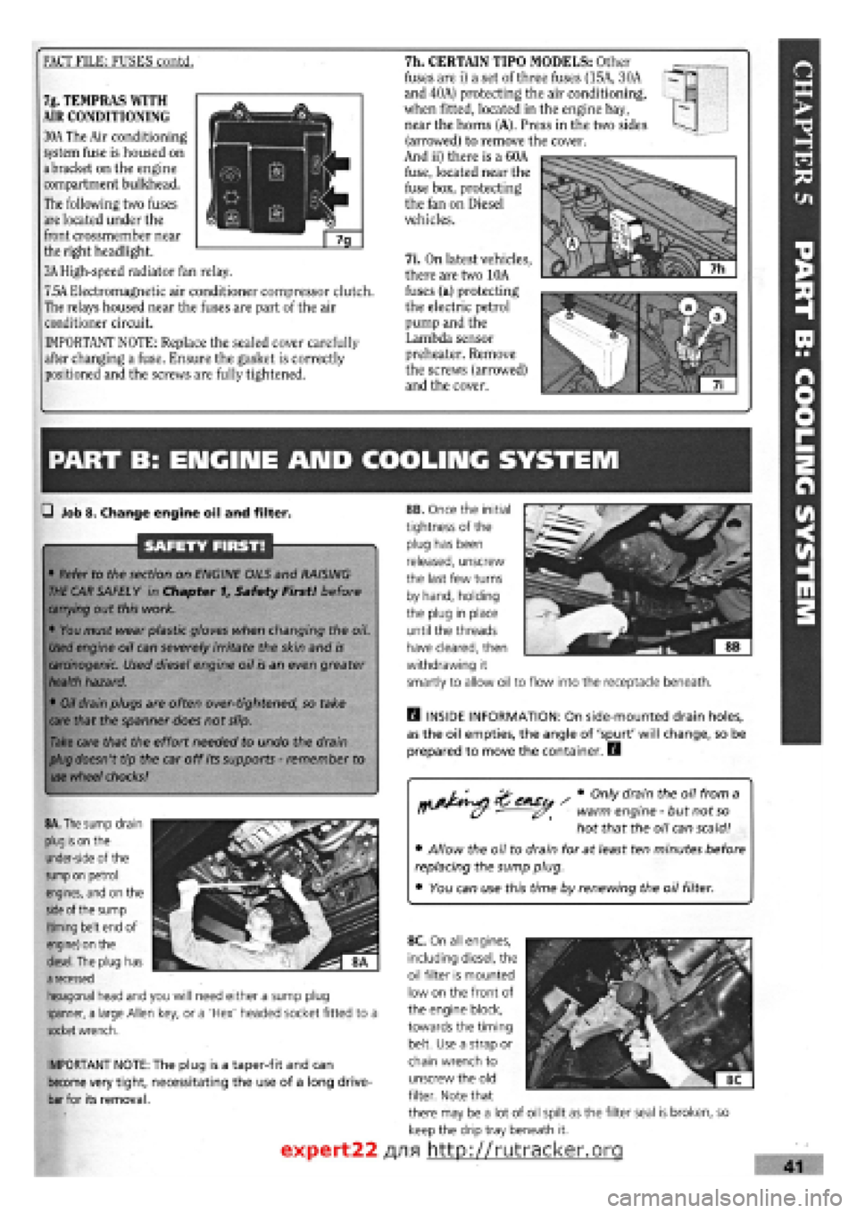
FACT FILE: FUSES contd. 7h. CERTAIN TIPO MODELS: Other
fuses are i) a set of three fuses (15A, 30A
and 40A) protecting the air conditioning,
when fitted, located in the engine bay,
near the horns (A). Press in the two sides
(arrowed) to remove the cover.
And ii) there is a 60A
fuse, located near the
fuse box, protecting
the fan on Diesel
vehicles.
7i. On latest vehicles,
there are two 10A
fuses (a) protecting
the electric petrol
pump and the
Lambda sensor
preheater. Remove
the screws (arrowed)
and the cover.
7g. TEMPRAS WITH
AIR CONDITIONING
30A The Air conditioning
system fuse is housed on
a bracket on the engine
compartment bulkhead.
The following two fuses
are located under the
front crossmember near
the right headlight.
3A High-speed radiator fan relay.
7.5A Electromagnetic air conditioner compressor clutch.
The relays housed near the fuses are part of the air
conditioner circuit.
IMPORTANT NOTE: Replace the sealed cover carefully
after changing a fuse. Ensure the gasket is correctly
positioned and the screws are fully tightened.
PART B: ENGIIME AND COOLING SYSTEM
Q Job 8. Change engine oil and filter.
SAFETY FIRST!
• Refer to the section on ENGINE OILS and RAISING
THE
CAR SAFELY in Chapter f, Safety First! before
carrying
out this work.
• You must wear plastic gloves when changing the oil.
Used
engine oil can severely irritate the skin and
is
carcinogenic.
Used diesel engine oil is an even greater
health
hazard.
•
Oil
drain plugs are often over-tightened, so take
care
that the spanner does not slip.
Take
care that the effort needed to undo the drain
plug
doesn't tip the car off its supports
-
remember to
use
wheel
chocks!
rtj&^si ' # °nly dram theu 0,7 fr°m a ff (y warm engine
-
but not
so
hot that the oil can scald!
• Allow the oil to drain for at least ten minutes before
replacing the sump plug.
• You can use this time by renewing the oil filter.
IMPORTANT NOTE: The plug is a taper-fit and can
become very tight, necessitating the use of a long drive-
bar for its removal.
H INSIDE INFORMATION: On side-mounted drain holes,
as the oil empties, the angle of 'spurt' will change, so be
prepared to move the container. E3
8A. The
sump drain
plug is on
the
under-side of the
sump on
petrol
engines, and on the
side
of the sump
(timing belt end of
engine) on the
diesel.
The plug has
a
recessed
hexagonal head and you will need either a sump plug
spanner, a large Allen key, or a 'Hex' headed socket fitted to a
socket
wrench.
8B. Once the initial
tightness of the
plug has been
released, unscrew
the last few turns
by hand, holding
the plug in place
until the threads
have cleared, then
withdrawing it
smartly to allow oil to flow into the receptacle beneath.
expert22
8C. On all engines,
including diesel, the
oil filter is mounted
low on the front of
the engine block,
towards the timing
belt. Use a strap or
chain wrench to
unscrew the old
filter. Note that
there may be a lot of oil spilt as the filter seal is broken, so
keep the drip tray beneath it.
/yifl http://rutracker.org
Page 39 of 171
—I Job 13. Check cooling system.
SAFETY FIRST!
• The coolant level should be checked
-
and the
cooling system worked on, ONLY WHEN THE
COOLANT IS COLD. If you remove the pressure cap or
bleed screws when the engine is hot, scalding coolant
will spurt out.
• Keep anti-freeze away from children. If it is acciden-
tally swallowed or contacts skin or eyes, rinse
immediately with plenty of water and seek immediate
medical help.
Examine the cooling system hoses, looking for signs of
splitting, chafing and perishing. Squeeze the top and bottom
radiator hoses. Any hard, brittle areas or crackling sounds tell
you that the hoses are decomposing from the inside
-
replace-
ments needed!
SAFETY FIRST!
If
a
clearance is outside the tolerances shown in Chapter 3,
Facts
and Figures, the relevant shim will have to be changed.
New
shims
are available from your FIAT dealer. This work is
fully described in Chapter
6,
Repairs and Replacements.
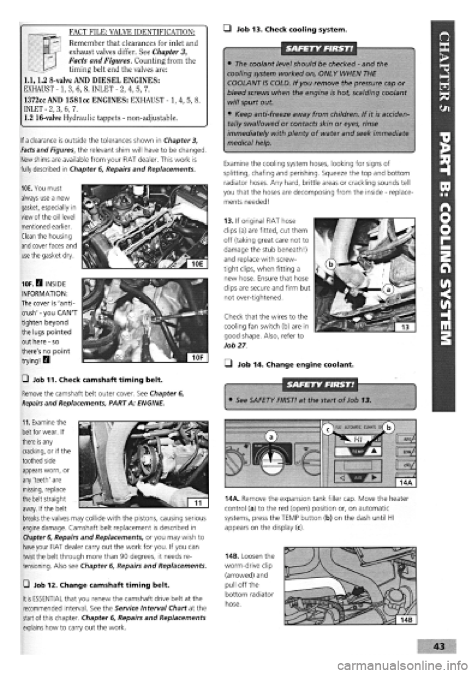
10E. You must
always use a new
gasket, especially in
view of the oil level
mentioned earlier.
Clean the housing
and
cover faces and
use
the gasket dry.
11.
Examine the
belt
for wear. If
there
is
any
cracking, or if the
toothed side
10F.H INSIDE
INFORMATION:
The cover is 'anti-
crush'
-
you CAN'T
tighten beyond
the lugs pointed
out here
-
so
there's no point
trying! H
0 Job 11. Check camshaft timing belt.
Remove the camshaft belt outer cover. See Chapter 6,
Repairs
and Replacements, PART A: ENGINE.
FACT FILE: VALVE IDENTIFICATION:
T
—
Remember that clearances for inlet and
3™ exhaust valves differ. See
Chapter
3,
Facts and Figures. Counting from the
—^ timing belt end the valves are:
1.1,1.2 8-valve AND DIESEL ENGINES:
EXHAUST -1, 3, 6, 8. INLET
-
2, 4, 5, 7.
1372cc AND 1581cc ENGINES: EXHAUST -1, 4, 5, 8.
INLET
-
2, 3, 6, 7.
1.2 16-valve Hydraulic tappets
-
non-adjustable.
13. If original FIAT hose
clips (a) are fitted, cut them
off (taking great care not to
damage the stub beneath!)
and replace with screw-
tight clips, when fitting a
new hose. Ensure that hose
clips are secure and firm but
not over-tightened.
Check that the wires to the
cooling fan switch (b) are in
good shape. Also, refer to
Job
27
• Job 14. Change engine coolant.
• See SAFETY FIRST! at the start of Job 13.
appears worn, or
any 'teeth' are
missing, replace
the belt straight
away. If the belt
breaks
the valves may collide with the pistons, causing serious
engine damage. Camshaft belt replacement is described in
Chapter 6,
Repairs and Replacements, or you may wish to
have
your FIAT dealer carry out the work for you. If you can
twist the belt through more than 90 degrees, it needs re-
tensioning. Also see Chapter
6,
Repairs and Replacements.
m
AUtOKAlIC CtMAU s/
b
14A. Remove the expansion tank filler cap. Move the heater
control (a) to the red (open) position or, on automatic
systems, press the TEMP button (b) on the dash until HI
appears on the display (c).
—i Job 12. Change camshaft timing belt.
It is
ESSENTIAL that you renew the camshaft drive belt at the
recommended interval. See the Service Interval Chart at the
start
of this chapter. Chapter
6,
Repairs and Replacements
explains how to carry out the work.
14B. Loosen the
worm-drive clip
(arrowed) and
pull off the
bottom radiator
hose.
Page 40 of 171
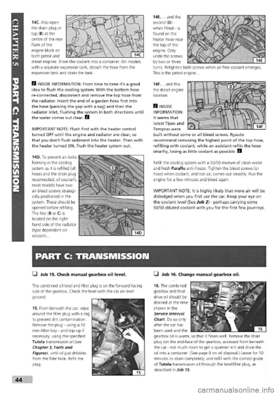
14C. Also open
the drain plug or
tap (B) at the
centre of the rear
flank of the
engine block on
both petrol and
diesel engines. Drain the coolant into a container. On models
with a separate expansion tank, detach the hose from the
expansion tank and drain the tank.
Q INSIDE INFORMATION: From time to time it's a good
idea to flush the cooling system. With the bottom hose
re-connected, disconnect and remove the top hose from
the radiator. Insert the end of a garden hose first into
the hose (packing the gap with a rag) and then the
radiator inlet, flushing the system in both directions until
the water comes out clear. Q
IMPORTANT NOTE: Flush first with the heater control
turned OFF until the engine and radiator are clear, so
that you don't flush sediment into the heater. Then with
the heater turned ON, flush the heater system out.
14D. To prevent air-locks
forming in the cooling
system as it is refilled (all
hoses and the drain plug
reconnected, of course!),
most models have two
air-bleed screws strategi-
cally positioned in the
system. These should be
opened before refilling.
The first (B or C) is
located on the right-
hand side of the radiator
(type dependant on
version)...
PART C: TRANSMISSION
• Job 15. Check manual gearbox oil level.
The combined oil level and filler plug is on the forward-facing
side of the gearbox. Check the level with the car on level
ground.
15. From beneath the car, wipe
around the filler plug with a rag
to prevent dirt contamination.
Remove the plug
-
using a 10
mm Allen key
-
and top-up if
necessary, using the specified
Tutela transmission oil (see
Chapter
3,
Facts and
Figures), until oil just dribbles
from the filler hole. Refit the
plug.
14E.... and the
second (D)
-
when fitted
-
is
found on the
heater hose near
the top of the
engine. Only
undo the screws
by two or three
turns. Retighten both screws when air-free coolant emerges.
This is the petrol engine...
14F. ...and this
the diesel engine
location.
H INSIDE
INFORMATION:
It seems that
latest Tipos and
Tempras were
built without some or all bleed screws. Ryauto
recommend removing the highest point of the top hose,
refilling with coolant, while an assistant refits the hose
smartly, losing as little coolant as possible. D
Refill the cooling system with a 50/50 mixture of clean water
and fresh Paraflu anti-freeze. Tighten the bleed screws (or
hose) when coolant, and not air, comes out steadily. Run the
engine for a few minutes and bleed again.
IMPORTANT NOTE: It is highly likely that more air will be
dislodged when you first use the car. Keep your eye on
the coolant level (See Job 2)
-
perhaps carrying some
50/50 diluted coolant with you for the first few journeys.
• Job 16. Change manual gearbox oil.
16. The combined
gearbox and final
drive oil should be
drained at the time
shown in the
Service Interval
Chart. Do so only
after the car has
been used and the
gearbox oil is warm, so that it flows well. Remove the drain
plug (on the end-face of the gearbox, accessed from beneath
the car
-
not much room to get a spanner in!) and drain the
oil into a container. (See page 8 on oil disposal.) Leave for 10
minutes to drain completely, and refill with the correct grade
of Tutela transmission oil through the level/filler plug, as
described in Job 15.
Page 84 of 171
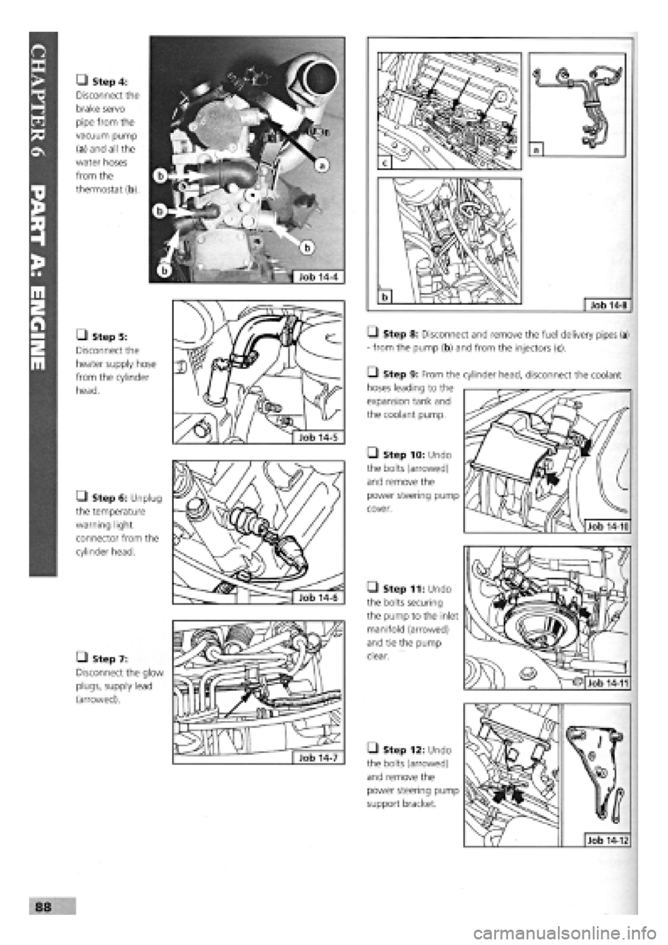
• Step 4:
Disconnect the
brake servo
pipe from the
vacuum pump
(a) and all the
water hoses
from the
thermostat (b).
• Step 5:
Disconnect the
heater supply hose
from the cylinder
head.
• Step 6: Unplug
the temperature
warning light
connector from the
cylinder head.
• Step 7:
Disconnect the glow
plugs, supply lead
(arrowed).
Q Step 8: Disconnect and remove the fuel delivery pipes (a)
- from the pump (b) and from the injectors (c).
• Step 9: From the
hoses leading to the
expansion tank and
the coolant pump.
• Step 10: Undo
the bolts (arrowed)
and remove the
power steering pump
cover.
• Step 11: Undo
the bolts securing
the pump to the inlet
manifold (arrowed)
and tie the pump
clear.
• Step 12: Undo
the bolts (arrowed)
and remove the
power steering pump
support bracket.
88
cylinder head, disconnect the coolant
Job 14-10
Job 14-12
Job 14-11
Page 117 of 171
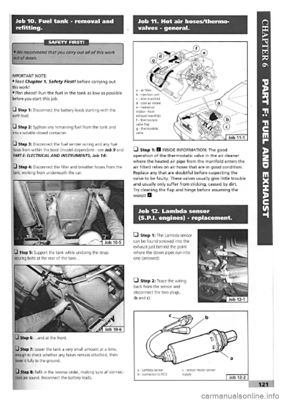
Job 10. Fuel tank - removal and
refitting.
Job 11. Hot air hoses/thermo-
valves - general.
SAFETY FIRST!
Job 12. Lambda sensor
(S.P.I, engines) - replacement.
• We recommend that you carry out all of this work
out of
doors.
I
IMPORTANT NOTE:
• Read Chapter 1, Safety First! before carrying out
this
work!
• Plan ahead! Run the fuel in the tank as low as possible
before you start this job.
Q Step 1: Disconnect the battery leads starting with the
earth lead.
• Step 2: Syphon any remaining fuel from the tank and
into a suitable closed container.
Q Step 3: Disconnect the fuel sender wiring and any fuel
hoses
from within the boot (model-dependent
-
see Job 9 and
PARTE: ELECTRICAL AND INSTRUMENTS, Job 14).
• Step 4: Disconnect the filler and breather hoses from the
tank,
working from underneath the car.
a - Lambda sensor b - connector to ECU c - sensor heater power supply Job 12-2
Q Step 5: Support the tank while undoing the strap
securing bolts at the rear of the tank...
Q Step 6: ...and at the front.
Q Step 7: Lower the tank a very small amount at a time,
enough to check whether any hoses remain attached, then
lower it fully to the ground.
Q Step 8: Refit in the reverse order, making sure all connec-
tions are
sound. Reconnect the battery leads.
• Step 1: H INSIDE INFORMATION: The good
operation of the thermostatic valve in the air cleaner
where the heated air pipe from the manifold enters the
air filter) relies on air hoses that are in good condition.
Replace any that are doubtful before suspecting the
valve to be faulty. These valves usually give little trouble
and usually only suffer from sticking, caused by dirt.
Try cleaning the flap and hinge before assuming the
worst! Q
• Step 1: The Lambda sensor
can be found screwed into the
exhaust just behind the point
where the down pipes run into
one (arrowed).
Q Step 2: Trace the wiring
back from the sensor and
disconnect the two plugs,
(b and c).
a - air filter b - injection unit c - inlet manifold d - cool air intake e - heated air intake - from exhaust manifold f
-
thermostatic valve flap g - thermostatic valve
Job 11-1
Page 151 of 171
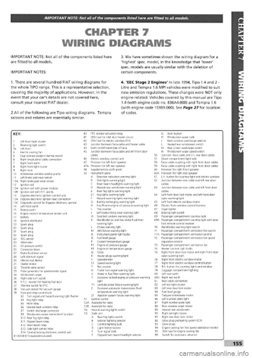
IMPORTANT NOTE: Not all of the components listed here are fitted to all models.
CHAPTER 7
WIRING DIAGRAMS
IMPORTANT NOTE: Not all of the components listed here
are fitted to all models.
IMPORTANT NOTES:
3. We have sometimes shown the wiring diagram for a
'highest' spec, model, in the knowledge that 'lower'
spec, models are usually similar with the deletion of
certain components.
1. There are several hundred FIAT wiring diagrams for
the whole TIPO range. This is a representative selection,
covering the majority of applications. However, in the
event that your car's details are not covered here,
consult your nearest FIAT dealer.
2 All of the following are Tipo wiring diagrams. Tempra
saloons and estates are essentially similar.
4. 'EEC Stage 2 Engines' In late 1994, Tipo 1.4 and 2 -
Litre and Tempra 1.6 MPI vehicles were modified to suit
new emission regulations. These changes were NOT only
engine-related. Vehicles covered by this manual are Tipo
1.4 (with engine code no. 836A4.000) and Tempra 1.6
(with engine code 159B9.000). See Page 27 for location
of codes.
KEY:
1 Left front light cluster 2 Reversing light switch 3a Left horn 4 Electric cooling fan 5 Dual contact coolant thermal switch 6 Right longitudinal cable connection 7 Right front earth 8 Right front light cluster 9 Right horn 10 Screen/rear window washer pump 11 Left brake pad wear sensor 11A Right brake pad wear sensor 12 Ignition coil 12A Ignition coil with power module 12B Ignition coil with H.T. points 13 Digiplex electronic ignition control unit 13A Digiplex electronic ignition lead connection 13C Diagnostic socket for Digiplex electronic ignition 14 Left front earth 15 Battery earth 16 Engine coolant temperature sender unit 17 Battery 18 Ignition distributor 19 Sparkplug 20 Spark plug 21 Sparkplug 22 Spark plug 23 TDC sensor 24 Alternator 25 Oil pressure switch 26 Connector block 27 Brake fluid level sensor 28 Left side turn signal 30 Idle cut-out device 31 Starter motor 32 Throttle valve sensor 33 Pulse generator for speedometer signal 34 Windscreen wiper 35 Right side turn signal 36 P.T.C. resistor for heating fuel duct 37 Thermal switch for PTC 38 Vacuum sensor for vacuum gauge 39 Fuse and relay control unit E2 Turn signal and hazard warning light flasher E4 Fog light relay E5 Horn relay E6 Heated back window relay E7 Switch discharge connector E9 Windscreen wiper intermittent function E10 Rear fog light relay E11 Dipped beam relay E12 Main beam relay E13 Side light control relay E14 Central locking electronic control unit E1-E3-E8-E15-available (unused)
40 PTC resistor activation relay 41 20A fuse for inlet duct heater circuit 42 25A fuse for electric window ECU 43 Junction between facia cable and heater cable 44 Earth on left hand side of facia 45 Junction between facia cable and left front door
G Horn button H Windscreen wiper stalk I Back window wash/wipe selector L Heated rear windscreen switch M Rear screen wash/wipe switch N Windscreen wiper speed switch cables 56 Junction: facia cable and r.h. rear door cables Electric window control unit 57 Glove compartment light bulb Provision for left front speaker 58 Facia cable coupling with right front door cables Provision for left rear speaker 59 Facia cable coupling with right front door cables Supplementary earth point 60 Provision for right front speaker Instrument panel 60A Provision for right rear speaker A Direction indicators warning light 61 L.h. button for courtesy light and electric window B Side lights warning light 62 Junction between rear cable and left rear door C Main beam headlights warning light cables D Heated rear windscreen warning light 63 Junction between rear cable and left front door E Rear fog lights warning light cables E1 Fog lights warning light 64 Left front door lock motor and left front door F Hazard warning lights warning light open warning light G Battery recharging warning light 65 Left front electric window motor H Insufficient engine oil pressure warning light 66 Electric front window control buttons I Trip counter 67 Cigar lighter J Left brake lining wear warning light 68 Braking light switch J1 Seat belt undone warning light 69 Passenger compartment courtesy light K Handbrake on and low brake fluid level 69A Passenger compartment courtesy light with door warning light lock remote control receiver L Choke warning light 70 Hand brake warning light switch M ABS failure warning light 71 Passenger compartment ventilation fan switch N Instrument panel light bulbs 71A Passenger compartment ventilation control 0 Fuel level gauge 72 Passenger compartment ventilation fan speed P Coolant temperature gauge regulation resistor P1 Engine oil pressure gauge 73 Passenger compartment ventilation fan P2 Engine oil temperature gauge 74 Heater controls light bulbs Q Clock 75 Right front door lock motor and right front door R Heater plugs warning light open warning light S Speedometer 76 Right front electric window motor S1 Speed warning light 77 Right front electric window control button T Rev counter 78 R.h. button for courtesy lights and window U Trailer turn signal warning light 79 Luggage compartment lighting X Water in fuel filter warning light 80 Left rear earth Y Excessive turbocharging air pressure warning 80A Right rear earth light 81 Rear cable connection Y1 Lambda probe failure warning light 82 Left tail-light cluster Z Excessive automatic transmission fluid 83 Left rear door lock motor temperature warning light 84 Fuel level gauge Z1 Injection system failure warning light 85 Tailgate lock/release motor Ignition switch 86 Left number plate light Available for radio 87 Right number plate light Available for radio 88 Rear window wiper motor Hazard warning lights switch 89 Heated rear windscreen Stalk unit 90 Right tail-light cluster A Rear fog lights switch 91 Right rear door lock motor B Exterior lighting selector 92 Glow plug preheating system ECU c Control lighting bulb 93 Glow plugs D Light flasher button 94 Engine cooling fan first speed additional resistor E Turn signal stalk 95 30A fuse for engine cooling fan F Dipped/main beam headlight selector 96 Switch for automatic advance
155