ignition FIAT TEMPRA 1988 Service And Repair Manual
[x] Cancel search | Manufacturer: FIAT, Model Year: 1988, Model line: TEMPRA, Model: FIAT TEMPRA 1988Pages: 171, PDF Size: 18.05 MB
Page 3 of 171
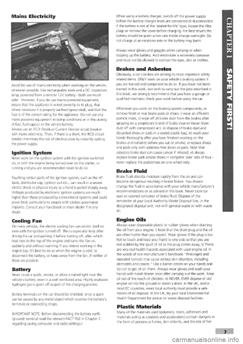
Mains Electricity
Avoid the use of mains electricity when working on the vehicle,
whenever possible. Use rechargeable tools and a DC inspection
lamp, powered from a remote 12V battery
-
both are much
safer. However, if you do use mains-powered equipment,
ensure that the appliance is wired correctly to its plug, that
where necessary it is properly earthed (grounded), and that the
fuse is of the correct rating for the appliance. Do not use any
mains powered equipment in damp conditions or in the vicinity
of fuel, fuel vapour or the vehicle battery.
Always use an RCD (Residual Current Device) circuit breaker
with mains electricity. Then, if there is a short, the RCD circuit
breaker minimises the risk of electrocution by instantly cutting
the power supply.
Ignition System
Never work on the ignition system with the ignition switched
on, or with the engine being turned over on the starter, or
running and you are recommended never to do so.
Touching certain parts of the ignition system, such as the HT
leads, distributor cap, ignition coil etc., can result in a severe
electric shock or physical injury as a hand is pulled sharply away.
Voltages produced by electronic ignition systems are much
higher than those produced by conventional systems and could
prove fatal, particularly to people with cardiac pacemaker
implants. Consult your handbook or main dealer if in any
doubt.
Cooling Fan
On many vehicles, the electric cooling fan can switch itself on
even with the ignition turned off. This is especially likely after
driving the car and parking it before turning off, after which
heat rises to the top of the engine and turns the fan on,
suddenly and without warning. If you intend working in the
engine bay, it's best to do so when the engine is cold, to
disconnect the battery, or keep away from the fan, if neither of
these are possible.
Battery
Never cause a spark, smoke, or allow a naked light near the
vehicle's battery, even in a well ventilated area. Highly explosive
hydrogen gas is given off as part of the charging process.
Battery terminals on the car should be shielded, since a spark
can be caused by any metal object which touches the battery's
terminals or connecting straps.
IMPORTANT NOTE: Before disconnecting the battery earth
(ground) terminal read the relevant FACT FILE in Chapter 5
regarding saving computer and radio settings.)
When using a battery charger, switch off the power supply
before the battery charger leads are connected or disconnected.
If the battery is not of the 'sealed-for-life' type, loosen the filler
plugs or remove the cover before charging. For best results the
battery should be given a low rate trickle charge overnight. Do
not charge at an excessive rate or the battery may burst.
Always wear gloves and goggles when carrying or when
topping up the battery. Acid electrolyte is extremely corrosive
and must not be allowed to contact the eyes, skin or clothes.
Brakes and Asbestos
Obviously, a car's brakes are among its most important safety
related items. ONLY work on your vehicle's braking system if
you are trained and competent to do so. If you have not been
trained in this work, but wish to carry out the jobs described in
this book, we strongly recommend that you have a garage or
qualified mechanic check your work before using the car.
Whenever you work on the braking system components, or
remove front or rear brake pads or shoes: i) wear an efficient
particle mask; ii) wipe off all brake dust from the brakes after
spraying on a proprietary brand of brake cleaner (never blow
dust off with compressed air); iii) dispose of brake dust and
discarded shoes or pads in a sealed plastic bag; iv) wash your
hands thoroughly after you have finished working on the
brakes and certainly before you eat or smoke; v) replace shoes
and pads only with asbestos-free shoes or pads. Note that
asbestos brake dust can cause cancer if inhaled; vi) always
replace brake pads and/or shoes in complete 'axle' sets of four
-
never replace the pads/shoes on one wheel only.
Brake Fluid
Brake fluid absorbs moisture rapidly from the air and can
become dangerous resulting in brake failure. You should
change the fluid in accordance with your vehicle manufacturer's
recommendations or as advised in this book. Never store (or
use) an opened container of brake fluid. Dispose of the
remainder at your Local Authority Waste Disposal Site, in the
designated disposal unit, not with general waste or with waste
oil.
Engine Oils
Always wear disposable plastic or rubber gloves when draining
the oil from your engine, i) Note that the drain plug and the oil
are often hotter than you expect. Wear gloves if the plug is too
hot to touch and keep your hand to one side so that you are
not scalded by the spurt of oil as the plug comes away; ii) There
are very real health hazards associated with used engine oil. In
the words of one manufacturer's handbook "Prolonged and
repeated contact may cause serious skin disorders, including
dermatitis and cancer." Use a barrier cream on your hands and
try not to get oil on them. Always wear gloves and wash your
hands with hand cleaner soon after carrying out the work. Keep
oil out of the reach of children; iii) NEVER, EVER dispose of old
engine oil into the ground or down a drain. In the UK, and in
most EC countries, every local authority must provide a safe
means of oil disposal. In the UK, try your local Environmental
Health Department for advice on waste disposal facilities.
Plastic Materials
Many of the materials used (polymers, resins, adhesives and
materials acting as catalysts and accelerators) contain dangers in
the form of poisonous fumes, skin irritants, and the risk of fire
Page 5 of 171
Please read the whole of the CHAPTER 1, SAFETY FIRST! before carrying out any work on your car.
CHAPTER 2
USING YOUR CAR
This Chapter is taken from
FIAT's own official Handbooks
on the Tipo and Tempra. It
contains important and
helpful information for the
operation of your FIAT Tipo or
Tempra.
KEYS AND LOCKS
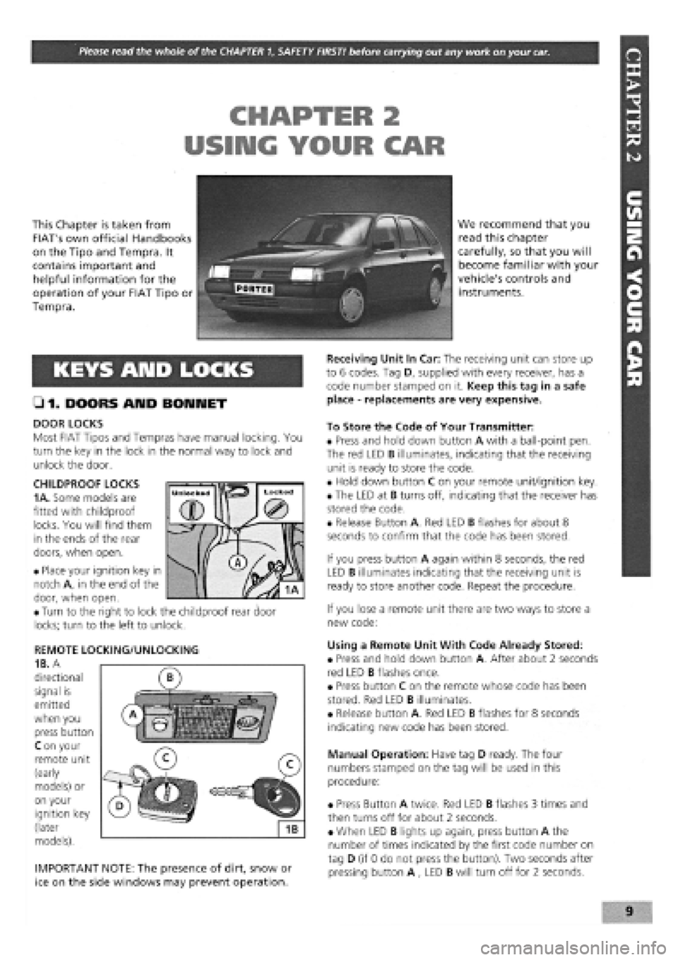
• 1. DOORS AMD BONNET
DOOR LOCKS
Most FIAT Tipos and Tempras have manual locking. You
turn the key in the lock in the normal way to lock and
unlock the door.
CHILDPROOF LOCKS
1 A.
Some models are
fitted with childproof
locks. You will find them
in the ends of the rear
doors, when open.
• Place your ignition key in
notch A, in the end of the
door, when open.
• Turn to the right to lock the childproof rear door
locks; turn to the left to unlock.
REMOTE LOCKING/UNLOCKING
1B. A
directional
signal is
emitted
when you
press button
C on your
remote unit
(early
models) or
on your
ignition key
(later
models).
IMPORTANT NOTE: The presence of dirt, snow or
ice on the side windows may prevent operation.
We recommend that you
read this chapter
carefully, so that you will
become familiar with your
vehicle's controls and
instruments.
Receiving Unit In Car: The receiving unit can store up
to 6 codes. Tag D, supplied with every receiver, has a
code number stamped on it. Keep this tag in a safe
place
-
replacements are very expensive.
To Store the Code of Your Transmitter:
• Press and hold down button A with a ball-point pen.
The red LED B illuminates, indicating that the receiving
unit is ready to store the code.
• Hold down button C on your remote unit/ignition key.
• The LED at B turns off, indicating that the receiver has
stored the code.
• Release Button A. Red LED B flashes for about 8
seconds to confirm that the code has been stored.
If you press button A again within 8 seconds, the red
LED B illuminates indicating that the receiving unit is
ready to store another code. Repeat the procedure.
If you lose a remote unit there are two ways to store a
new code:
Using a Remote Unit With Code Already Stored:
• Press and hold down button A. After about 2 seconds
red LED B flashes once.
• Press button C on the remote whose code has been
stored. Red LED B illuminates.
• Release button A. Red LED B flashes for 8 seconds
indicating new code has been stored.
Manual Operation: Have tag D ready. The four
numbers stamped on the tag will be used in this
procedure:
• Press Button A twice. Red LED B flashes 3 times and
then turns off for about 2 seconds.
• When LED B lights up again, press button A the
number of times indicated by the first code number on
tag D (if 0 do not press the button). Two seconds after
pressing button A , LED B will turn off for 2 seconds.
Page 6 of 171
• Repeat this operation three more times until the
complete code number has been entered, if the code
has been entered in correctly LED B will start flashing.
• Release button A (see illustration
1B).
Red LED B
flashes for 8 seconds indicating the new remote unit's
code has been stored.
IMPORTANT NOTE: If the LED does not illuminate
when remote unit button (illustration 1B, button
O is pressed, change the remote unit's battery.
• Insert the emergency key A into the emergency switch
slot in the glove compartment turn the key to the left to
switch the alarm off (see inset).
• Turn the key back towards its original position to
switch the alarm system back on.
IMPORTANT NOTE: As the alarm system absorbs
energy, if you are not planning on using the car
for a long period of time, turn the alarm exclusion
key to the off position, so as not to run the vehicle
battery down.
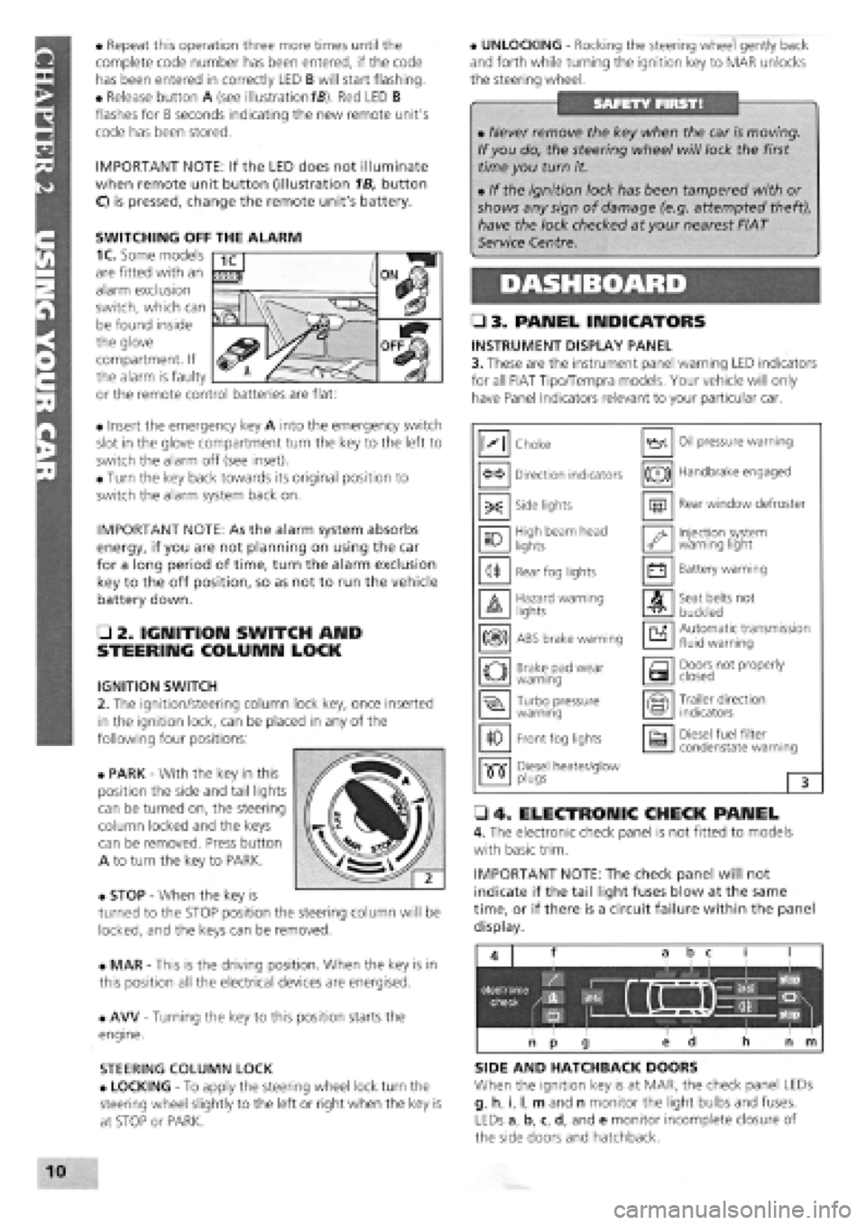
• 2. IGNITION SWITCH AND
STEERING COLUMN LOCK
IGNITION SWITCH
2. The ignition/steering column lock key, once inserted
in the ignition lock, can be placed in any of the
following four positions:
• PARK
-
With the key in this
position the side and tail lights
can be turned on, the steering
column locked and the keys
can be removed. Press button
A to turn the key to PARK.
• STOP
-
When the key is
turned to the STOP position the steering column will be
locked, and the keys can be removed.
• MAR
-
This is the driving position. When the key is in
this position all the electrical devices are energised.
• AW
-
Turning the key to this position starts the
engine.
STEERING COLUMN LOCK
• LOCKING
-
To apply the steering wheel lock turn the
steering wheel slightly to the left or right when the key is
at STOP or PARK.
• UNLOCKING
-
Rocking the steering wheel gently back
and forth while turning the ignition key to MAR unlocks
the steering wheel.
• 3. PANEL INDICATORS
INSTRUMENT DISPLAY PANEL
3. These are the instrument panel warning LED indicators
for all FIAT Tipo/Tempra models. Your vehicle will only
have Panel Indicators relevant to your particular car.
• 4. ELECTRONIC CHECK PANEL
4. The electronic check panel is not fitted to models
with basic trim.
IMPORTANT NOTE: The check panel will not
indicate if the tail light fuses blow at the same
time, or if there is a circuit failure within the panel
display.
SIDE AND HATCHBACK DOORS
When the ignition key is at MAR, the check panel LEDs
g, h, i, I, m and n monitor the light bulbs and fuses.
LEDs a, b, c, d, and e monitor incomplete closure of
the side doors and hatchback.
• Never remove the key when the car is moving.
If you do, the steering wheel will lock the first
time you turn it.
• If the ignition lock has been tampered with or
shows any sign of damage (e.g. attempted theft),
have the lock checked at your nearest FIAT
Service Centre.
M Choke Oil pressure warning
Direction indicators (®) Handbrake engaged
-X: Side lights m Rear window defroster
10 High beam head
lights '•y Injection system warning light
<1* Rear fog lights • Battery warning
A Hazard warning lights A Seat belts not
buckled
m ABS brake warning a Automatic transmission fluid warning
o Brake pad wear warning a Doors not properly closed
Turbo pressure warning Trailer direction indicators
10 Front fog lights a Diesel fuel filter condenstate warning
•515" Diesel heater/glow •515" plugs 3
SWITCHING OFF THE ALARM
1C. Some models
are fitted with an
alarm exclusion
switch, which can
be found inside
the glove
compartment. If
the alarm is faulty
or the remote control batteries are flat:
Page 12 of 171
EMERGENCY STARTING
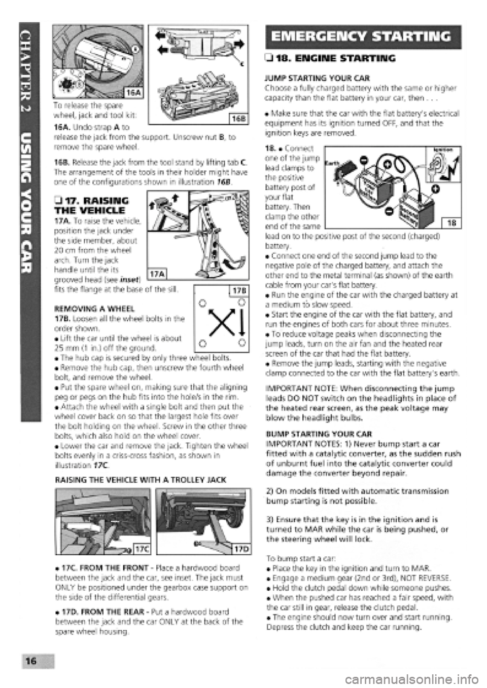
To release the spare
wheel, jack and tool kit:
16A. Undo strap A to
release the jack from the support. Unscrew nut B, to
remove the spare wheel.
16B. Release the jack from the tool stand by lifting tab C.
The arrangement of the tools in their holder might have
one of the configurations shown in illustration 16B.
• 17. RAISING
THE VEHICLE
17A. To raise the vehicle,
position the jack under
the side member, about
20 cm from the wheel
arch. Turn the jack
handle until the its
grooved head (see inset)
fits the flange at the base of the sill.
REMOVING A WHEEL
17B. Loosen all the wheel bolts in the
order shown.
• Lift the car until the wheel is about
25 mm
(1
in.) off the ground.
• The hub cap is secured by only three wheel bolts.
• Remove the hub cap, then unscrew the fourth wheel
bolt, and remove the wheel.
• Put the spare wheel on, making sure that the aligning
peg or pegs on the hub fits into the hole/s in the rim.
• Attach the wheel with a single bolt and then put the
wheel cover back on so that the largest hole fits over
the bolt holding on the wheel. Screw in the other three
bolts, which also hold on the wheel cover.
• Lower the car and remove the jack. Tighten the wheel
bolts evenly in a criss-cross fashion, as shown in
illustration 17C.
RAISING THE VEHICLE WITH A TROLLEY JACK
• 17C. FROM THE FRONT
-
Place a hardwood board
between the jack and the car, see inset. The jack must
ONLY be positioned under the gearbox case support on
the side of the differential gears.
• 17D. FROM THE REAR
-
Put a hardwood board
between the jack and the car ONLY at the back of the
spare wheel housing.
• 18. ENGINE STARTING
JUMP STARTING YOUR CAR
Choose a fully charged battery with the same or higher
capacity than the flat battery in your car, then ...
• Make sure that the car with the flat battery's electrical
equipment has its ignition turned OFF, and that the
ignition keys are removed.
18. • Connect
one of the jump
lead clamps to
the positive
battery post of
your flat
battery. Then
clamp the other
end of the same
lead on to the positive post of the second (charged)
battery.
• Connect one end of the second jump lead to the
negative pole of the charged battery, and attach the
other end to the metal terminal (as shown) of the earth
cable from your car's flat battery.
• Run the engine of the car with the charged battery at
a medium to slow speed.
• Start the engine of the car with the flat battery, and
run the engines of both cars for about three minutes.
• To reduce voltage peaks when disconnecting the
jump leads, turn on the air fan and the heated rear
screen of the car that had the flat battery.
• Remove the jump leads, starting with the negative
clamp connected to the car with the flat battery's earth.
IMPORTANT NOTE: When disconnecting the jump
leads DO NOT switch on the headlights in place of
the heated rear screen, as the peak voltage may
blow the headlight bulbs.
BUMP STARTING YOUR CAR
IMPORTANT NOTES: 1) Never bump start a car
fitted with a catalytic converter, as the sudden rush
of unburnt fuel into the catalytic converter could
damage the converter beyond repair.
2) On models fitted with automatic transmission
bump starting is not possible.
3) Ensure that the key is in the ignition and is
turned to MAR while the car is being pushed, or
the steering wheel will lock.
To bump start a car:
• Place the key in the ignition and turn to MAR.
• Engage a medium gear (2nd or 3rd), NOT REVERSE.
• Hold the clutch pedal down while someone pushes.
• When the pushed car has reached a fair speed, with
the car still in gear, release the clutch pedal.
• The engine should now turn over and start running.
Depress the clutch and keep the car running.
16
Page 15 of 171
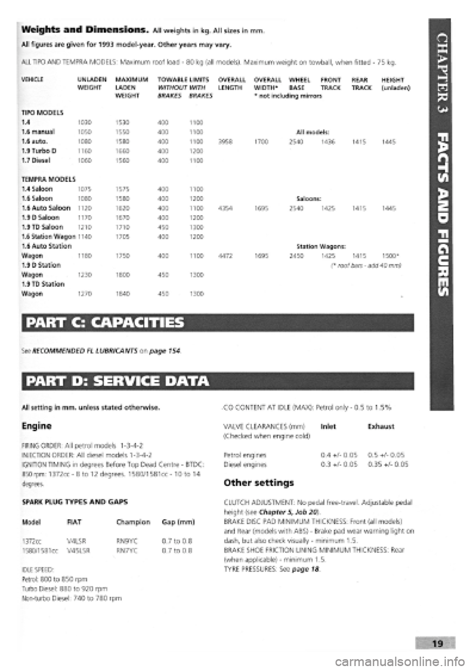
Weights and Dimensions. All weights in kg. All sizes in mm.
All figures are given for 1993 model-year. Other years may vary.
ALL TIPO AND TEMPRA MODELS: Maximum roof load
-
80 kg (all models). Maximum weight on towball, when fitted - 75 kg.
VEHICLE
TIPO MODELS
1.4
1.6 manual
1.6 auto.
1.9 Turbo D
1.7 Diesel
UNLADEN WEIGHT
1030
1050
1080
1160
1060
MAXIMUM
LADEN WEIGHT
1530
1550
1580
1660
1560
TOWABLE LIMITS WITHOUT WITH BRAKES BRAKES
400
400
400
400
400
1100
1100
1100
1200
1100
OVERALL LENGTH
3958
OVERALL WHEEL FRONT WIDTH* BASE TRACK * not including mirrors
1700
All models:
2540 1436
REAR TRACK
1415
HEIGHT (unladen)
1445
TEMPRA MODELS
1.4 Saloon 1075 1575 400 1100
1.6 Saloon 1080 1580 400 1200 Saloons:
1.6 Auto Saloon 1120 1620 400 1100 4354 1695 2540 1425 1415 1445
1.9 D Saloon 1170 1670 400 1200
1.9 TD Saloon 1210 1710 450 1300
1.6 Station Wagon 1140 1705 400 1200
1.6 Auto Station Station Wagons:
Wagon 1180 1750 400 1100 4472 1695 2450 1425 1415 1500*
1.9 D Station (* roof bars - add 40 mm)
Wagon 1230 1800 450 1300
1.9 TD Station
Wagon 1270 1840 450 1300
PART C: CAPACITIES
See RECOMMENDED EL LUBRICANTS on page 154.
PART D: SERVICE DATA
All setting in mm. unless stated otherwise.
Engine
FIRING ORDER: All petrol models 1-3-4-2
INJECTION ORDER: All diesel models 1-3-4-2
IGNITION TIMING in degrees Before Top Dead Centre
-
BTDC:
850 rpm: 1372cc-8to 12 degrees. 1580/1581cc- 10 to 14
degrees.
CO CONTENT AT IDLE (MAX): Petrol only
-
0.5 to 1.5%
Exhaust VALVE CLEARANCES (mm) Inlet
(Checked when engine cold)
Petrol engines
Diesel engines
Other settings
0.4
+/-
0.05
0.3
+/-
0.05
0.5
+/-
0.05
0.35
+/-
0.05
SPARK PLUG TYPES AND GAPS
Model FIAT
1372cc V4LSR
1580/1581
cc V45LSR
Champion Gap (mm)
RN9YC
RN7YC
IDLE SPEED:
Petrol: 800 to 850 rpm
Turbo Diesel: 880 to 920 rpm
Non-turbo Diesel: 740 to 780 rpm
0.7 to 0.8
0.7 to 0.8
CLUTCH ADJUSTMENT: No pedal free-travel. Adjustable pedal
height (see Chapter 5, Job 20).
BRAKE DISC PAD MINIMUM THICKNESS: Front (all models)
and Rear (models with ABS)
-
Brake pad wear warning light on
dash, but also check visually
-
minimum 1.5.
BRAKE SHOE FRICTION LINING MINIMUM THICKNESS: Rear
(when applicable)
-
minimum 1.5.
TYRE PRESSURES: See page 18
Page 24 of 171
Please read the whole of the CHAPTER 1, SAFETY FIRST! before carrying out any work on your car.
fUADTCSA I En Hr
GETTIIMG THROUGH THE MOT
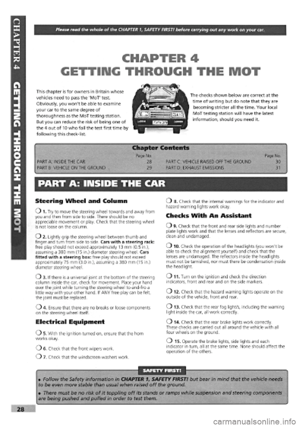
This chapter is for owners in Britain whose
vehicles need to pass the 'MoT' test.
Obviously, you won't be able to examine
your car to the same degree of
thoroughness as the MoT testing station.
But you can reduce the risk of being one of
the 4 out of 10 who fail the test first time by
following this check-list.
iMFTri
The checks shown below are correct at the
time of writing but do note that they are
becoming stricter all the time. Your local
MoT testing station will have the latest
information, should you need it.
1 p Chapter Contents -
Page No. Page No.
PART A: INSIDE THE CAR 28 PART C: VEHICLE RAISED OFF THE GROUND 30
PART B: VEHICLE ON THE GROUND 29 PART D: EXHAUST EMISSIONS 31
PART A: INSIDE THE CAR
Steering Wheel and Column
O 1. Try to move the steering wheel towards and away from you and then from side to side. There should be no appreciable movement or play. Check that the steering wheel is not loose on the column.
02 . Lightly grip the steering wheel between thumb and finger and turn from side to side. Cars with a steering rack: free play should not exceed approximately 13 mm (0.5 in.), assuming a 380 mm (15 in.) diameter steering wheel. Cars fitted with a steering box: free play should not exceed approximately 75 mm (3.0 in.), assuming a 380 mm (15 in.) diameter steering wheel.
Ob . If there is a universal joint at the bottom of the steering column inside the car, check for movement. Place your hand over the joint while turning the steering wheel to-and-fro a little way with your other hand. If ANY free play can be felt, the joint must be replaced.
04. Ensure that there are no breaks or loose components
on the steering wheel itself.
Electrical Equipment
OS . With the ignition turned on, ensure that the horn works okay.
OE . Check that the front wipers work.
07 . Check that the windscreen washers work.
o 8. Check that the internal warnings for the indicator and hazard warning lights work okay.
Checks With An Assistant
O9 . Check that the front and rear side lights and number plate lights work and that the lenses and reflectors are secure, clean and undamaged.
o 10. Check the operation of the headlights (you won't be able to check the alignment yourself) and check that the lenses are undamaged. The reflectors inside the headlights must not be tarnished, nor must there be condensation inside the headlight.
o 11. Turn on the ignition and check the direction
indicators, front and rear and on the side markers.
o 12. Check that the hazard warning lights operate on the
outside of the vehicle, front and rear.
o 13. Check that the rear fog light/s, including the warning
light inside the car, all work correctly.
o 14. Check that the rear brake lights work correctly. These checks are carried out all around the vehicle with all four wheels on the ground.
o 15. Operate the brake lights, side lights and each indicator in turn, all at the same time. None should affect the operation of the others.
SAFETY FIRST!
• Follow the Safety information in CHAPTER 1, SAFETY FIRST! but bear in mind that the vehicle needs
to be even more stable than usual when raised off the ground.
• There must be no risk of it toppling off its stands or ramps while suspension and steering components
are being pushed and pulled in order to test them.
Page 29 of 171
Thanks
are due to the excellent, knowledgeable and helpful staff at FIAT main dealers, Ryauto of Amblecote, in the West
Midlands for supplying vehicles and for their assistance with this chapter. In particular, thanks are due to the efficient Maurice
Hough, Service Manager, the experienced Foreman, Tony Morris, and young demon mechanic, Matthew Worsfold.
Some of the suggested inspection/replacement intervals may not correspond to those shown in the original handbook. The suggested
schedule, based on FIAT'S recommendations, takes into account the age of the vehicle and the annual MoT test in the UK.
In practice, because of the split between (mainly) 12 month/9,000 mile and 18 month/13,500 mile intervals, you will need to
service your Tipo or Tempra at most, if not every, 6 month interval.
IMPORTANT NOTE: Each service should be carried out at EITHER the recommended mileage OR the recommended time
interval, whichever comes first.
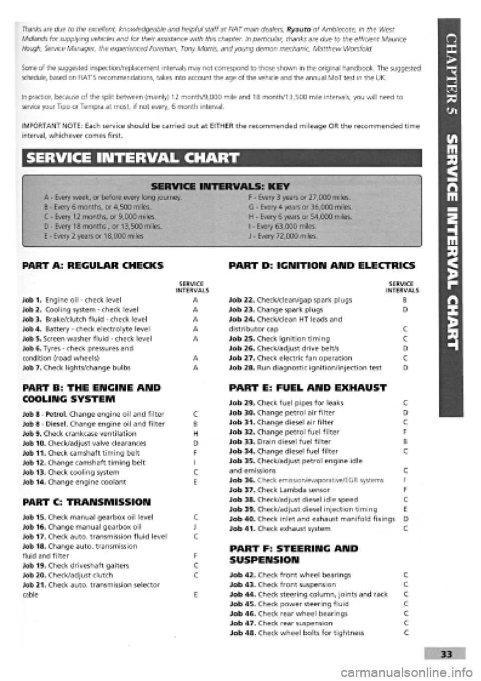
SERVICE INTERVAL CHART
SERVICE INTERVALS: KEY
A
-
Every week, or before every long journey. F
-
Every 3 years or 27,000 miles.
B
-
Every 6 months, or 4,500 miles. G
-
Every 4 years or 36,000 miles.
C - Every 12 months, or 9,000 miles. H
-
Every 6 years or 54,000 miles.
I
-
Every 63,000 miles. D - Every 18 months , or 13,500 miles.
H
-
Every 6 years or 54,000 miles.
I
-
Every 63,000 miles.
E
-
Every 2 years or 18,000 miles J
-
Every 72,000 miles.
PART A: REGULAR CHECKS
SERVICE INTERVALS
Job 1. Engine oil
-
check level A
Job 2. Cooling system
-
check level A
Job 3. Brake/clutch fluid
-
check level A
Job 4. Battery
-
check electrolyte level A
Job 5. Screen washer fluid
-
check level A
Job 6. Tyres
-
check pressures and
condition (road wheels) A
Job 7. Check lights/change bulbs A
PART B: THE ENGINE AND
COOLING SYSTEM
Job 8
-
Petrol. Change engine oil and filter C
Job 8
-
Diesel. Change engine oil and filter B
Job 9. Check crankcase ventilation H
Job 10. Check/adjust valve clearances D
Job 11. Check camshaft timing belt F
Job 12. Change camshaft timing belt I
Job 13. Check cooling system C
Job 14. Change engine coolant E
PART C: TRANSMISSION
Job 15. Check manual gearbox oil level C
Job 16. Change manual gearbox oil J
Job 17. Check auto, transmission fluid level C
Job 18. Change auto, transmission
fluid and filter F
Job 19. Check driveshaft gaiters C
Job 20. Check/adjust clutch C
Job 21. Check auto, transmission selector
cable E
PART D: IGNITION AND ELECTRICS
SERVICE INTERVALS
Job 22. Check/clean/gap spark plugs B
Job 23. Change spark plugs D
Job 24. Check/clean HT leads and
distributor cap C
Job 25. Check ignition timing C
Job 26. Check/adjust drive belt/s D
Job 27. Check electric fan operation C
Job 28. Run diagnostic ignition/injection test D
PART E: FUEL AND EXHAUST
Job 29. Check fuel pipes for leaks C
Job 30. Change petrol air filter D
Job 31. Change diesel air filter C
Job 32. Change petrol fuel filter F
Job 33. Drain diesel fuel filter B
Job 34. Change diesel fuel filter C
Job 35. Check/adjust petrol engine idle
and emissions C
Job 36. Check emission/evaporative/EGR systems F
Job 37. Check Lambda sensor F
Job 38. Check/adjust diesel idle speed C
Job 39. Check/adjust diesel injection timing E
Job 40. Check inlet and exhaust manifold fixings D
Job 41. Check exhaust system C
PART F: STEERING AND
SUSPENSION
Job 42. Check front wheel bearings C
Job 43. Check front suspension C
Job 44. Check steering column, joints and rack C
Job 45. Check power steering fluid C
Job 46. Check rear wheel bearings C
Job 47. Check rear suspension C
Job 48. Check wheel bolts for tightness C
Page 30 of 171
PART G: BRAKING SYSTEM
Job 49. Check front brakes
Job 50. Check rear brakes
Job 51. Check/adjust handbrake
Job 52. Check brake pipes
Job 53. Change brake hydraulic fluid
SERVICE INTERVALS
C
C
C
C
E
Job 56. Check seat and seat belt mountings C
Job 57. Check headlight alignment C
Job 58. Check underbody C
Job 59. Check spare tyre B
Job 60. Change pollen filter C
Job 61. Replace airbag gas generator 10 years
PART I: ROAD TEST
PART H: BODYWORK & INTERIOR
Job 54. Lubricate hinges and locks
Job 55. Check windscreen
Job 62. Road test and specialist check. AFTER EVERY
SERVICE
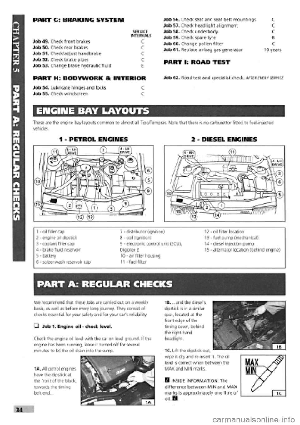
ENGINE BAY LAYOUTS
These are the engine bay layouts common to almost all Tipo/Tempras. Note that there is no carburettor fitted to fuel-injected
vehicles.
1 - PETROL ENGINES 2 - DIESEL ENGINES
1
-
oil filler cap 7
-
distributor (ignition) 12 - oil filter location
2
-
engine oil dipstick 8
-
coil (ignition) 13
-
fuel pump (mechanical)
3
-
coolant filler cap 9
-
electronic control unit (ECU), 14
-
diesel injection pump
4 - brake fluid reservoir Digiplex 2 15
-
alternator location (behind engine)
5 - battery 10
-
air filter housing
6
-
screenwash reservoir cap 11
-
fuel filter
PART A: REGULAR CHECKS
1B. ...and the diesel's
dipstick is in a similar
spot, located at the
front edge of the
timing cover, behind
the right-hand
headlight.
Q INSIDE INFORMATION: The
difference between MIN and MAX
marks is approximately one litre of
oil. Q
We recommend that these Jobs are carried out on a weekly
basis, as well as before every long journey. They consist of
checks essential for your safety and for your car's reliability.
• Job 1. Engine oil
-
check level.
Check the engine oil level with the car on level ground. If the
engine has been running, leave it turned off for several
minutes to let the oil drain into the sump.
1A. All petrol engines
have the dipstick at
the front of the block,
towards the timing
belt end...
1C. Lift the dipstick out,
wipe it dry and re-insert it. The oil
level is correct when between the
MAX and MIN marks.
Page 31 of 171
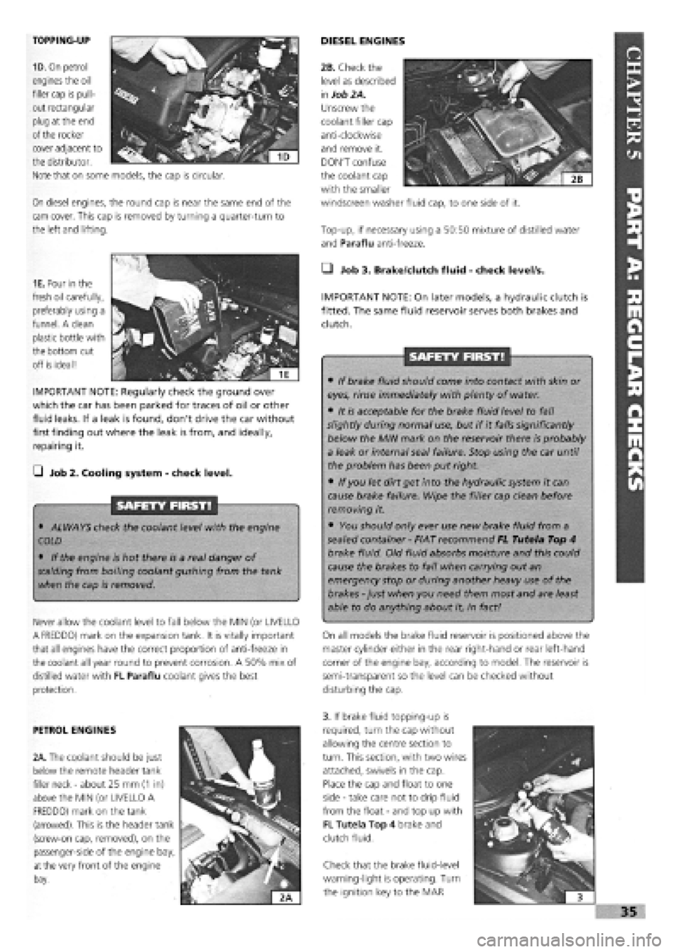
TOPPING-UP
1D. On petrol
engines the oil
filler cap is pull-
out rectangular
plug at the end
of the rocker
On diesel engines, the round cap is near the same end of the
cam cover. This cap is removed by turning a quarter-turn to
the left and lifting.
DIESEL ENGINES
Top-up, if necessary using a 50:50 mixture of distilled water
and Paraflu anti-freeze.
cover adjacent to
the distributor.
Note that on some models, the cap is circular.
1E. Pour in the
fresh oil carefully,
preferably using a
funnel. A clean
plastic bottle with
the bottom cut
off is ideal!
IMPORTANT NOTE: Regularly check the ground over
which the car has been parked for traces of oil or other
fluid leaks. If a leak is found, don't drive the car without
first finding out where the leak is from, and ideally,
repairing it.
G Job 2. Cooling system
-
check level.
SAFETY FIRST!
• ALWAYS check the coolant level with the engine
COLD
• If the engine is hot there is a real danger of
scalding
from boiling coolant gushing from the tank
when the cap is removed.
Never allow the coolant level to fall below the MIN (or UVELLO
A FREDDO) mark on the expansion tank. It is vitally important
that all engines have the correct proportion of anti-freeze in
the coolant all year round to prevent corrosion. A 50% mix of
distilled water with FL Paraflu coolant gives the best
protection.
• Job 3. Brake/dutch fluid
-
check level/s.
IMPORTANT NOTE: On later models, a hydraulic clutch is
fitted. The same fluid reservoir serves both brakes and
clutch.
SAFETY FIRST!
• If brake fluid should come into contact with skin or
eyes, rinse immediately with plenty of water.
• It is acceptable for the brake fluid level to fall
slightly during normal use, but if it falls significantly
below the MIN mark on the reservoir there is probably
a leak or internal seal failure. Stop using the car until
the problem has been put right.
• If you let dirt get into the hydraulic system it can
cause brake failure. Wipe the filler cap clean before
removing it.
• You should only ever use new brake fluid from a
sealed container
-
FIAT recommend FL Tutela Top 4
brake fluid. Old fluid absorbs moisture and this could
cause the brakes to fail when carrying out an
emergency stop or during another heavy use of the
brakes
-
just when you need them most and are least
able to do anything about it, in fact!
On all models the brake fluid reservoir is positioned above the
master cylinder either in the rear right-hand or rear left-hand
corner of the engine bay, according to model. The reservoir is
semi-transparent so the level can be checked without
disturbing the cap.
PETROL ENGINES
2A. The coolant should be just
below the remote header tank
filler neck
-
about 25 mm
(1
in)
above the MIN (or UVELLO A
FREDDO) mark on the tank
(arrowed). This is the header tank
(screw-on cap, removed), on the
passenger-side of the engine bay,
at
the very front of the engine
bay.
3. If brake fluid topping-up is
required, turn the cap without
allowing the centre section to
turn. This section, with two wires
attached, swivels in the cap.
Place the cap and float to one
side
-
take care not to drip fluid
from the float
-
and top up with
FL Tutela Top 4 brake and
clutch fluid.
Check that the brake fluid-level
warning-light is operating. Turn
the ignition key to the MAR
I
i 3
»35
2B. Check the
level as described
in
Job 2A.
Unscrew the
coolant filler cap
anti-clockwise
and remove it.
DON'T confuse
the coolant cap
with the smaller
windscreen washer fluid cap, to one side of it.
Page 32 of 171
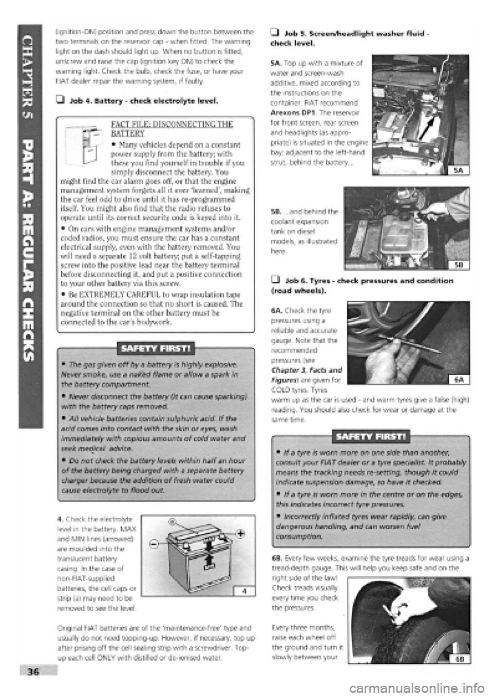
(ignition-ON) position and press down the button between the
two terminals on the reservoir cap
-
when fitted. The warning
light on the dash should light up. When no button is fitted,
unscrew and raise the cap (ignition key ON) to check the
warning light. Check the bulb, check the fuse, or have your
FIAT dealer repair the warning system, if faulty.
• Job 4. Battery
-
check electrolyte level.
FACT FILE: DISCONNECTING THE
BATTERY
• Many vehicles depend on a constant
power supply from the battery; with
these you find yourself in trouble if you
simply disconnect the battery. You
might find the car alarm goes off, or that the engine
management system forgets all it ever 'learned', making
the car feel odd to drive until it has re-programmed
itself. You might also find that the radio refuses to
operate until its correct security code is keyed into it.
• On cars with engine management systems and/or
coded radios, you must ensure the car has a constant
electrical supply, even with the battery removed. You
will need a separate 12 volt battery; put a self-tapping
screw into the positive lead near the battery terminal
before disconnecting it, and put a positive connection
to your other battery via this screw.
• Be EXTREMELY CAREFUL to wrap insulation tape
around the connection so that no short is caused. The
negative terminal on the other battery must be
connected to the car's bodywork.
SAFETY FIRST!
• The gas given off by a battery is highly explosive.
Never smoke, use a naked flame or allow a spark in
the battery compartment.
• Never disconnect the battery (it can cause sparking)
with the battery caps removed.
• All vehicle batteries contain sulphuric acid. If the
acid comes into contact with the skin or eyes, wash
immediately with copious amounts of cold water and
seek medjcal advice.
• Do not check the battery levels within half an hour
of the battery being charged with a separate battery
charger because the addition of fresh water could
cause electrolyte to flood out.
4. Check the electrolyte
level in the battery. MAX
and MIN lines (arrowed)
are moulded into the
translucent battery
casing. In the case of
non-FIAT-supplied
batteries, the cell caps or
strip (a) may need to be
removed to see the level.
Original FIAT batteries are of the 'maintenance-free' type and
usually do not need topping-up. However, if necessary, top up
after prising off the cell sealing strip with a screwdriver. Top-
up each cell ONLY with distilled or de-ionised water.
• Job 5. Screen/headlight washer fluid
check level.
5A. Top up with a mixture of
water and screen-wash
additive, mixed according to
the instructions on the
container. FIAT recommend
Arexons DP1. The reservoir
for front screen, rear screen
and headlights (as appro-
priate) is situated in the engine
bay: adjacent to the left-hand
strut, behind the battery...
5B. ...and behind the
coolant expansion
tank on diesel
models, as illustrated
here.
• Job 6. Tyres
-
check pressures and condition
(road wheels).
/
6A. Check the tyre
pressures using a
reliable and accurate
gauge. Note that the
recommended
pressures (see
Chapter
3,
Facts and
Figures) are given for ^^
iH^KKSEI ^ "'
COLD tyres. Tyres
warm up as the car is used
-
and warm tyres give a false (high)
reading. You should also check for wear or damage at the
same time.
SAFETY FIRST!
• If a tyre is worn more on one side than another,
consult your FIAT dealer or a tyre specialist. It probably
means the tracking needs re-setting, though it could
indicate suspension damage, so have it checked.
• If a tyre is worn more in the centre or on the edges,
this indicates incorrect tyre pressures.
• Incorrectly inflated tyres wear rapidly, can give
dangerous handling, and can worsen fuel
consumption.
Every three months,
raise each wheel off
the ground and turn it
slowly between your
36
6B. Every few weeks, examine the tyre treads for wear using a
tread-depth gauge. This will help you keep safe and on the
right side of the law!
Check treads visually
every time you check
the pressures.