spark plugs replace FIAT TEMPRA 1988 Service And Repair Manual
[x] Cancel search | Manufacturer: FIAT, Model Year: 1988, Model line: TEMPRA, Model: FIAT TEMPRA 1988Pages: 171, PDF Size: 18.05 MB
Page 3 of 171
Mains Electricity
Avoid the use of mains electricity when working on the vehicle,
whenever possible. Use rechargeable tools and a DC inspection
lamp, powered from a remote 12V battery
-
both are much
safer. However, if you do use mains-powered equipment,
ensure that the appliance is wired correctly to its plug, that
where necessary it is properly earthed (grounded), and that the
fuse is of the correct rating for the appliance. Do not use any
mains powered equipment in damp conditions or in the vicinity
of fuel, fuel vapour or the vehicle battery.
Always use an RCD (Residual Current Device) circuit breaker
with mains electricity. Then, if there is a short, the RCD circuit
breaker minimises the risk of electrocution by instantly cutting
the power supply.
Ignition System
Never work on the ignition system with the ignition switched
on, or with the engine being turned over on the starter, or
running and you are recommended never to do so.
Touching certain parts of the ignition system, such as the HT
leads, distributor cap, ignition coil etc., can result in a severe
electric shock or physical injury as a hand is pulled sharply away.
Voltages produced by electronic ignition systems are much
higher than those produced by conventional systems and could
prove fatal, particularly to people with cardiac pacemaker
implants. Consult your handbook or main dealer if in any
doubt.
Cooling Fan
On many vehicles, the electric cooling fan can switch itself on
even with the ignition turned off. This is especially likely after
driving the car and parking it before turning off, after which
heat rises to the top of the engine and turns the fan on,
suddenly and without warning. If you intend working in the
engine bay, it's best to do so when the engine is cold, to
disconnect the battery, or keep away from the fan, if neither of
these are possible.
Battery
Never cause a spark, smoke, or allow a naked light near the
vehicle's battery, even in a well ventilated area. Highly explosive
hydrogen gas is given off as part of the charging process.
Battery terminals on the car should be shielded, since a spark
can be caused by any metal object which touches the battery's
terminals or connecting straps.
IMPORTANT NOTE: Before disconnecting the battery earth
(ground) terminal read the relevant FACT FILE in Chapter 5
regarding saving computer and radio settings.)
When using a battery charger, switch off the power supply
before the battery charger leads are connected or disconnected.
If the battery is not of the 'sealed-for-life' type, loosen the filler
plugs or remove the cover before charging. For best results the
battery should be given a low rate trickle charge overnight. Do
not charge at an excessive rate or the battery may burst.
Always wear gloves and goggles when carrying or when
topping up the battery. Acid electrolyte is extremely corrosive
and must not be allowed to contact the eyes, skin or clothes.
Brakes and Asbestos
Obviously, a car's brakes are among its most important safety
related items. ONLY work on your vehicle's braking system if
you are trained and competent to do so. If you have not been
trained in this work, but wish to carry out the jobs described in
this book, we strongly recommend that you have a garage or
qualified mechanic check your work before using the car.
Whenever you work on the braking system components, or
remove front or rear brake pads or shoes: i) wear an efficient
particle mask; ii) wipe off all brake dust from the brakes after
spraying on a proprietary brand of brake cleaner (never blow
dust off with compressed air); iii) dispose of brake dust and
discarded shoes or pads in a sealed plastic bag; iv) wash your
hands thoroughly after you have finished working on the
brakes and certainly before you eat or smoke; v) replace shoes
and pads only with asbestos-free shoes or pads. Note that
asbestos brake dust can cause cancer if inhaled; vi) always
replace brake pads and/or shoes in complete 'axle' sets of four
-
never replace the pads/shoes on one wheel only.
Brake Fluid
Brake fluid absorbs moisture rapidly from the air and can
become dangerous resulting in brake failure. You should
change the fluid in accordance with your vehicle manufacturer's
recommendations or as advised in this book. Never store (or
use) an opened container of brake fluid. Dispose of the
remainder at your Local Authority Waste Disposal Site, in the
designated disposal unit, not with general waste or with waste
oil.
Engine Oils
Always wear disposable plastic or rubber gloves when draining
the oil from your engine, i) Note that the drain plug and the oil
are often hotter than you expect. Wear gloves if the plug is too
hot to touch and keep your hand to one side so that you are
not scalded by the spurt of oil as the plug comes away; ii) There
are very real health hazards associated with used engine oil. In
the words of one manufacturer's handbook "Prolonged and
repeated contact may cause serious skin disorders, including
dermatitis and cancer." Use a barrier cream on your hands and
try not to get oil on them. Always wear gloves and wash your
hands with hand cleaner soon after carrying out the work. Keep
oil out of the reach of children; iii) NEVER, EVER dispose of old
engine oil into the ground or down a drain. In the UK, and in
most EC countries, every local authority must provide a safe
means of oil disposal. In the UK, try your local Environmental
Health Department for advice on waste disposal facilities.
Plastic Materials
Many of the materials used (polymers, resins, adhesives and
materials acting as catalysts and accelerators) contain dangers in
the form of poisonous fumes, skin irritants, and the risk of fire
Page 29 of 171
Thanks
are due to the excellent, knowledgeable and helpful staff at FIAT main dealers, Ryauto of Amblecote, in the West
Midlands for supplying vehicles and for their assistance with this chapter. In particular, thanks are due to the efficient Maurice
Hough, Service Manager, the experienced Foreman, Tony Morris, and young demon mechanic, Matthew Worsfold.
Some of the suggested inspection/replacement intervals may not correspond to those shown in the original handbook. The suggested
schedule, based on FIAT'S recommendations, takes into account the age of the vehicle and the annual MoT test in the UK.
In practice, because of the split between (mainly) 12 month/9,000 mile and 18 month/13,500 mile intervals, you will need to
service your Tipo or Tempra at most, if not every, 6 month interval.
IMPORTANT NOTE: Each service should be carried out at EITHER the recommended mileage OR the recommended time
interval, whichever comes first.
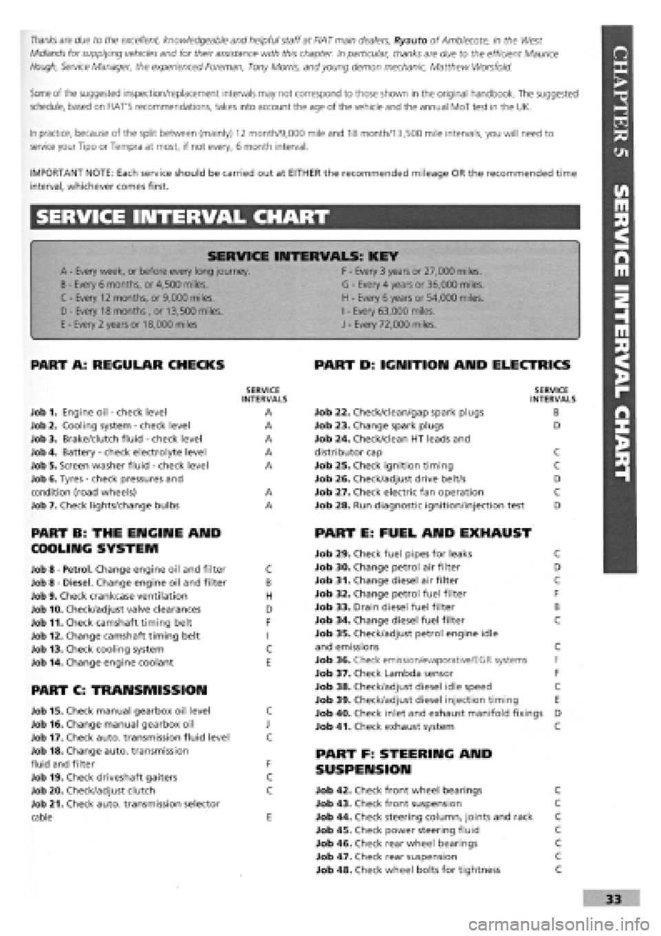
SERVICE INTERVAL CHART
SERVICE INTERVALS: KEY
A
-
Every week, or before every long journey. F
-
Every 3 years or 27,000 miles.
B
-
Every 6 months, or 4,500 miles. G
-
Every 4 years or 36,000 miles.
C - Every 12 months, or 9,000 miles. H
-
Every 6 years or 54,000 miles.
I
-
Every 63,000 miles. D - Every 18 months , or 13,500 miles.
H
-
Every 6 years or 54,000 miles.
I
-
Every 63,000 miles.
E
-
Every 2 years or 18,000 miles J
-
Every 72,000 miles.
PART A: REGULAR CHECKS
SERVICE INTERVALS
Job 1. Engine oil
-
check level A
Job 2. Cooling system
-
check level A
Job 3. Brake/clutch fluid
-
check level A
Job 4. Battery
-
check electrolyte level A
Job 5. Screen washer fluid
-
check level A
Job 6. Tyres
-
check pressures and
condition (road wheels) A
Job 7. Check lights/change bulbs A
PART B: THE ENGINE AND
COOLING SYSTEM
Job 8
-
Petrol. Change engine oil and filter C
Job 8
-
Diesel. Change engine oil and filter B
Job 9. Check crankcase ventilation H
Job 10. Check/adjust valve clearances D
Job 11. Check camshaft timing belt F
Job 12. Change camshaft timing belt I
Job 13. Check cooling system C
Job 14. Change engine coolant E
PART C: TRANSMISSION
Job 15. Check manual gearbox oil level C
Job 16. Change manual gearbox oil J
Job 17. Check auto, transmission fluid level C
Job 18. Change auto, transmission
fluid and filter F
Job 19. Check driveshaft gaiters C
Job 20. Check/adjust clutch C
Job 21. Check auto, transmission selector
cable E
PART D: IGNITION AND ELECTRICS
SERVICE INTERVALS
Job 22. Check/clean/gap spark plugs B
Job 23. Change spark plugs D
Job 24. Check/clean HT leads and
distributor cap C
Job 25. Check ignition timing C
Job 26. Check/adjust drive belt/s D
Job 27. Check electric fan operation C
Job 28. Run diagnostic ignition/injection test D
PART E: FUEL AND EXHAUST
Job 29. Check fuel pipes for leaks C
Job 30. Change petrol air filter D
Job 31. Change diesel air filter C
Job 32. Change petrol fuel filter F
Job 33. Drain diesel fuel filter B
Job 34. Change diesel fuel filter C
Job 35. Check/adjust petrol engine idle
and emissions C
Job 36. Check emission/evaporative/EGR systems F
Job 37. Check Lambda sensor F
Job 38. Check/adjust diesel idle speed C
Job 39. Check/adjust diesel injection timing E
Job 40. Check inlet and exhaust manifold fixings D
Job 41. Check exhaust system C
PART F: STEERING AND
SUSPENSION
Job 42. Check front wheel bearings C
Job 43. Check front suspension C
Job 44. Check steering column, joints and rack C
Job 45. Check power steering fluid C
Job 46. Check rear wheel bearings C
Job 47. Check rear suspension C
Job 48. Check wheel bolts for tightness C
Page 43 of 171
J Job 22. Check/clean/gap spark plugs. Q Job 23. Change spark plugs.
GENERAL. On all Tipo and Tempra petrol engines the spark
plugs
face forwards, allowing easy working access.
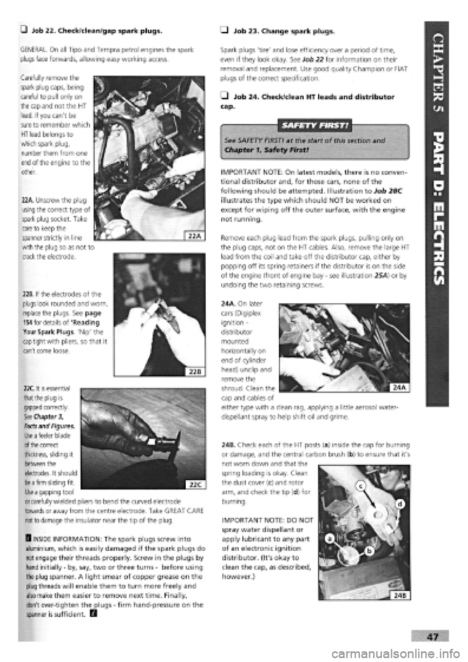
Carefully remove the
spark plug caps, being
careful to pull only on
the cap and
not the HT
lead. If you can't be
sure
to remember which
HT lead
belongs to
which spark plug,
number them from one
end
of the engine to the
other.
22B. If the electrodes of the
plugs look rounded and worn,
replace
the plugs. See page
154
for details of 'Reading
Your Spark Plugs. Nip' the
cap
tight with pliers, so that it
can't come loose.
Spark plugs 'tire' and lose efficiency over a period of time,
even if they look okay. See Job 22 for information on their
removal and replacement. Use good quality Champion or FIAT
plugs of the correct specification.
• Job 24. Check/dean HT leads and distributor
cap.
See SAFETY FIRST! at the start of this section and
Chapter 1, Safety First!
IMPORTANT NOTE: On latest models, there is no conven-
tional distributor and, for those cars, none of the
following should be attempted. Illustration to Job 28C
illustrates the type which should NOT be worked on
except for wiping off the outer surface, with the engine
not running.
Remove each plug lead from the spark plugs, pulling only on
the plug caps, not on the HT cables. Also, remove the large HT
lead from the coil and take off the distributor cap, either by
popping off its spring retainers if the distributor is on the side
of the engine (front of engine bay
-
see illustration 25A) or by
undoing the two retaining screws.
24A. On later
cars (Digiplex
ignition -
distributor
mounted
horizontally on
end of cylinder
head) unclip and
remove the
22A. Unscrew the plug
using
the correct type of
spark plug socket. Take
care
to keep the
spanner strictly in line
with the plug so as not to
crack the electrode.
22C.
it
is
essential
that the
plug is
gapped
correctly.
See Chapter 3,
Facts
and Figures.
Use a
feeler blade
of the
correct
thickness, sliding it
between
the
electrodes. It should
be a firm
sliding fit.
Use a
gapping tool
or
carefully wielded pliers to bend the curved electrode
towards
or away from the centre electrode. Take GREAT CARE
not to
damage the insulator near the tip of the plug.
H INSIDE INFORMATION: The spark plugs screw into
aluminium, which is easily damaged if the spark plugs do
not
engage their threads properly. Screw in the plugs by
hand initially
-
by, say, two or three turns
-
before using
the plug spanner. A light smear of copper grease on the
plug
threads will enable them to turn more freely and
also
make them easier to remove next time. Finally,
don't over-tighten the plugs
-
firm hand-pressure on the
spanner is sufficient. D
IMPORTANT NOTE: DO NOT
spray water dispellant or
apply lubricant to any part
of an electronic ignition
distributor. (It's okay to
clean the cap, as described,
however.)
shroud. Clean the
cap and cables of
either type with a clean rag, applying a little aerosol water-
dispellant spray to help shift oil and grime.
24B. Check each of the HT posts (a) inside the cap for burning
or damage, and the central carbon brush (b) to ensure that it's
not worn down and that the
spring loading is okay. Clean
the dust cover (c) and rotor
arm, and check the tip (d) for
burning.
Page 46 of 171
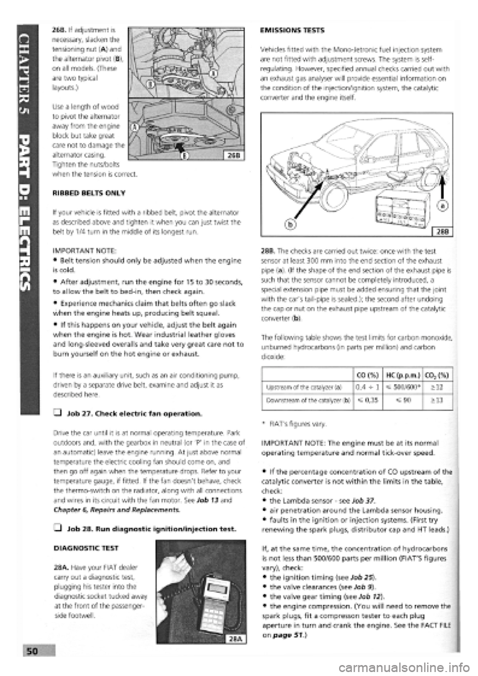
26B. If adjustment is
necessary, slacken the
tensioning nut (A) and
the alternator pivot (B),
on all models. (These
are two typical
layouts.)
Use a length of wood
to pivot the alternator
away from the engine
block but take great
care not to damage the
alternator casing.
Tighten the nuts/bolts
when the tension is correct.
RIBBED BELTS ONLY
If your vehicle is fitted with a ribbed belt, pivot the alternator
as described above and tighten it when you can just twist the
belt by 1/4 turn in the middle of its longest run.
IMPORTANT NOTE:
• Belt tension should only be adjusted when the engine
is cold.
• After adjustment, run the engine for 15 to 30 seconds,
to allow the belt to bed-in, then check again.
• Experience mechanics claim that belts often go slack
when the engine heats up, producing belt squeal.
• If this happens on your vehicle, adjust the belt again
when the engine is hot. Wear industrial leather gloves
and long-sleeved overalls and take very great care not to
burn yourself on the hot engine or exhaust.
If there is an auxiliary unit, such as an air conditioning pump,
driven by a separate drive belt, examine and adjust it as
described here.
Q Job 27. Check electric fan operation.
Drive the car until it is at normal operating temperature. Park
outdoors and, with the gearbox in neutral (or 'P' in the case of
an automatic) leave the engine running. At just above normal
temperature the electric cooling fan should come on, and
then go off again when the temperature drops. Refer to your
temperature gauge, if fitted. If the fan doesn't behave, check
the thermo-switch on the radiator, along with all connections
and wires in its circuit with the fan motor. See Job 13 and
Chapter
6,
Repairs and Replacements.
• Job 28. Run diagnostic ignition/injection test.
DIAGNOSTIC TEST
28A. Have your FIAT dealer
carry out a diagnostic test,
plugging his tester into the
diagnostic socket tucked away
at the front of the passenger-
side footwell.
EMISSIONS TESTS
Vehicles fitted with the Mono-Jetronic fuel injection system
are not fitted with adjustment screws. The system is self-
regulating. However, specified annual checks carried out with
an exhaust gas analyser will provide essential information on
the condition of the injection/ignition system, the catalytic
converter and the engine itself.
28B. The checks are carried out twice: once with the test
sensor at least 300 mm into the end section of the exhaust
pipe (a). (If the shape of the end section of the exhaust pipe is
such that the sensor cannot be completely introduced, a
special extension pipe must be added ensuring that the joint
with the car's tail-pipe is sealed.); the second after undoing
the cap or nut on the exhaust pipe upstream of the catalytic
converter (b).
The following table shows the test limits for carbon monoxide,
unburned hydrocarbons (in parts per million) and carbon
dioxide:
CO (%) HC (p.p.m.) C02(%)
Upstream of the catalyzer (a) 0,4 -h 1 500/600* >12
Downstream of the catalyzer (b)
=£
0,35 =s 90 >13
* FIAT's figures vary.
IMPORTANT NOTE: The engine must be at its normal
operating temperature and normal tick-over speed.
• if the percentage concentration of CO upstream of the
catalytic converter is not within the limits in the table,
check:
• the Lambda sensor
-
see Job 37.
• air penetration around the Lambda sensor housing.
• faults in the ignition or injection systems. (First try
renewing the spark plugs, distributor cap and HT leads.)
If, at the same time, the concentration of hydrocarbons
is not less than 500/600 parts per million (FIAT'S figures
vary), check:
• the ignition timing (see Job 25).
• the valve clearances (see Job 9).
• the valve gear timing (see Job 12).
• the engine compression. (You will need to remove the
spark plugs, fit a compresson tester to each plug
aperture in turn and crank the engine. See the FACT FILE
on page 51.)
Page 61 of 171
PART A: ENGINE
PART A: Contents
Job 1. Petrol engine. Timing belt
-
replacement and Job 12. Petrol engine. Mountings
-
replacement.
adjustment. Job 13. Diesel engine. Timing belt
-
replacement and
Job 2. Petrol engine. Cylinder head
-
removal. adjustment. •
Job 3. Petrol engine. Cylinder head and camshaft housing -Job 14. Diesel engine. Cylinder head
-
removal.
refitting. Job 15. Diesel engine. Cylinder head
-
refitting.
Job
4.
Petrol engine. Cylinder head
-
dismantling and Job 16. Diesel engine. Cylinder head
-
overhaul.
overhauling. Job 17. Diesel engine. Valve clearances
-
adjustment.
Job 5. Petrol engine
-
dismantling. Job 18. Diesel engine
-
removal.
Job
6.
Petrol engine
-
checking and reassembly. Job 19. Diesel engine
-
refitting.
Job
7.
Petrol engine. Valve clearances
-
adjustment. Job 20. Diesel engine. Mountings
-
replacement.
Job 8. Petrol engine/transmission
-
removal. Job 21. Diesel engine/transmission (removed from car)
-
Job
9.
Petrol engine/transmission
-
refitting. separation.
Job 10. Petrol engine/transmission (removed from car)
-
Job 22. Diesel engine/transmission (removed from car)
-
separation. reconnection.
Job 11. Petrol engine/transmission (removed from car)
-
Job 23. Diesel engine
-
dismantling.
reconnection. Job 24. Diesel engine
-
reassembly.
Job 1. Petrol engine. Timing belt
- replacement and adjustment.
Mi*^^ Zc+sc, / • The crankshaft pulley nut
n^^ will be difficult to turn.
• If the engine is in the car,
engage a gear (or 'Park' in the case of an automatic)
and have an assistant hold the footbrake down very
firmly. This will stop the engine from turning.
• Alternatively, with the starter motor removed, you
can have a helper prevent the flywheel ring gear from
turning with a large screwdriver.
• Step 4: Before removing the belt, put the pulley nut back
onto the crankshaft, take the car out of gear (if the engine is
still in the car) and remove the spark plugs. You can now turn
the engine in a clockwise direction using the refitted crank
pulley nut
-
without the pulley, of course!
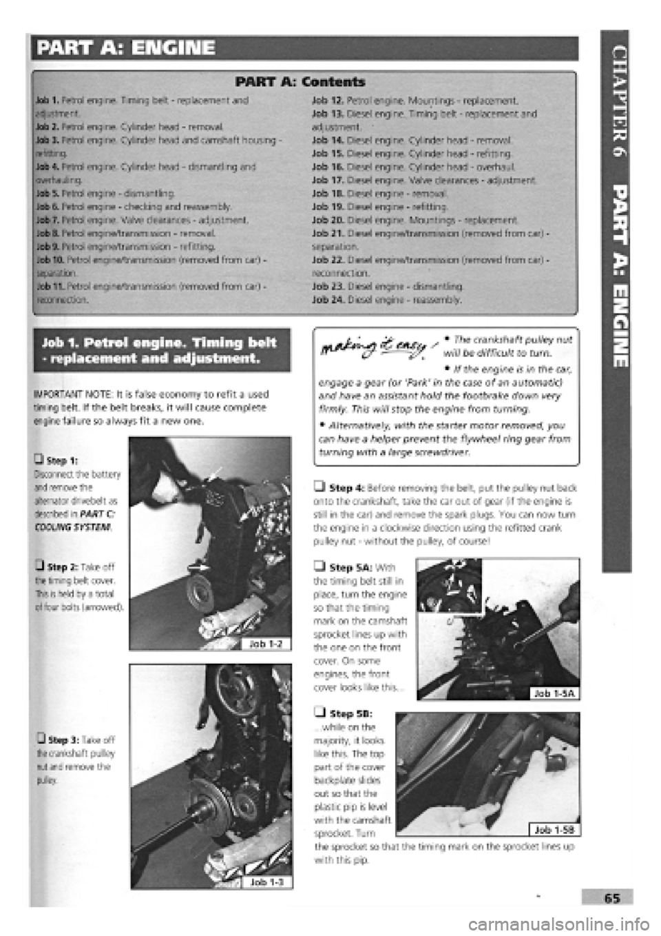
• Step 5A: With
the timing belt still in
place, turn the engine
so that the timing
mark on the camshaft
sprocket lines up with
the one on the front
cover. On some
engines, the front
cover looks like this...
• Step 5B:
...while on the
majority, it looks
like this. The top
part of the cover
backplate slides
out so that the
plastic pip is level
with the camshaft
sprocket. Turn
the sprocket so that the timing mark on the sprocket lines up
with this pip.
IMPORTANT NOTE: It is false economy to refit a used
timing belt. If the belt breaks, it will cause complete
engine failure so always fit a new one.
• Step 1:
Disconnect the battery
and
remove the
alternator drivebelt as
described in PART C:
COOLING
SYSTEM
0 Step 2: Take off
the timing
belt cover.
This is held
by a total
of
four bolts (arrowed).
• Step 3: Take off
the
crankshaft pulley
nut and
remove the
pulley.
Page 74 of 171
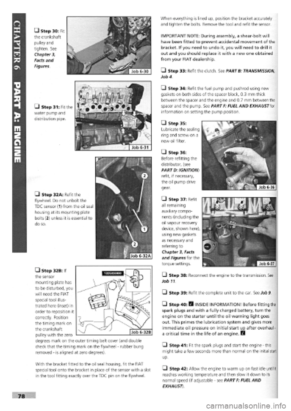
• Step 30: Fit
the crankshaft
pulley and
tighten. See
Chapter 3,
Facts and
Figures.
• Step 31: Fit the
water pump and
distribution pipe.
• Step 32A: Refit the
flywheel. Do not unbolt the
TDC sensor (1) from the oil seal
housing at its mounting plate
bolts
(2)
unless it is essential to
do so.
• Step 32B: If
the sensor
mounting plate has
to be disturbed, you
will need the FIAT
special tool illus-
trated here (inset) in
order to reposition it
correctly. Position
the timing mark on
the crankshaft
pulley with the zero
degrees mark on the outer timing belt cover (and double
check that the timing mark on the flywheel
-
rubber bung
removed
-
is aligned at zero degrees).
With the bracket fitted to the oil seal housing, fit the FIAT
special tool onto the bracket in place of the sensor with a slot
in the tool fitting exactly over the TDC pin on the flywheel.
When everything is lined up, position the bracket accurately
and tighten the bolts. Remove the tool and refit the sensor.
IMPORTANT NOTE: During assembly, a shear-bolt will
have been fitted to prevent accidental movement of the
bracket. If you need to undo it, you will need to drill it
out and you should replace it with a new one obtained
from your FIAT dealership.
• Step 33: Refit the clutch. See PARTB: TRANSMISSION,
Job 4.
Q Step 34: Refit the fuel pump and pushrod using new
gaskets on both sides of the spacer block, 0.3 mm thick
between the spacer and the engine and 0.7 mm between the
spacer and the pump. See PART F: FUEL AND EXHAUST for
information on setting the pump position.
• Step 35:
Lubricate the sealing
ring and screw on a
new oil filter.
• Step 36:
Before refitting the
distributor, (see
PART D: IGNITION)
refit, if necessary,
the oil pump drive
gear.
• Step 37: Refit
all remaining
auxiliary compo-
nents (including the
oil vapour recovery
device, shown here),
using new gaskets
as necessary and
referring to
Chapter
3,
Facts
and Figures for the
torque settings.
Q Step 38: Reconnect the engine to the transmission. See
Job 11.
Q Step 39: Refit the complete unit to the car. See Job
9.
• Step 40: fl INSIDE INFORMATION! Before fitting the
spark plugs and with a fully charged battery, turn the
engine on the starter until the oil warning light goes
out. This primes the lubrication system and gives more
immediate oil pressure on initial start up after overhaul-
a critical time in the life of an engine. B
• Step 41: Fit the spark plugs and start the engine
-
this
might take a few seconds more than normal on the initial start
up.
• Step 42: Allow the engine to warm up on fast idle
until
it
reaches working temperature and then slow it down to its
normal speed (if adjustable
-
see PART F: FUEL AND
EXHAUST)
Page 75 of 171
G Step 43: Stop the engine and allow it to cool, check the
oil
and coolant levels and look for any leaks.
G Step 44: Avoid over-rewing or overloading the engine
during its settling down period of 600 miles. We recommend
an oil
and filter change at this mileage
-
this will help to
extend the life of your new engine.
Job 7. Petrol engine.
Valve clearances - adjustment.
0 INSIDE INFORMATION! Adjustment should always be
made with the engine cold. B
G Step 1: Remove the camshaft cover and the spark plugs.
Jack up a front wheel and engage top gear. Turning the wheel
will rotate the engine and therefore the camshaft. If the
engine
is
out of the car, use a socket and long lever on the
crankshaft pulley nut. If the cylinder head is detached, turn
the
camshaft belt sprocket, by hand.
G Step 2: The inlet and exhaust valves use different clear-
ances
which are checked when each cam lobe is pointing
directly away from its follower. See Chapter
3,
Facts and
Figures.
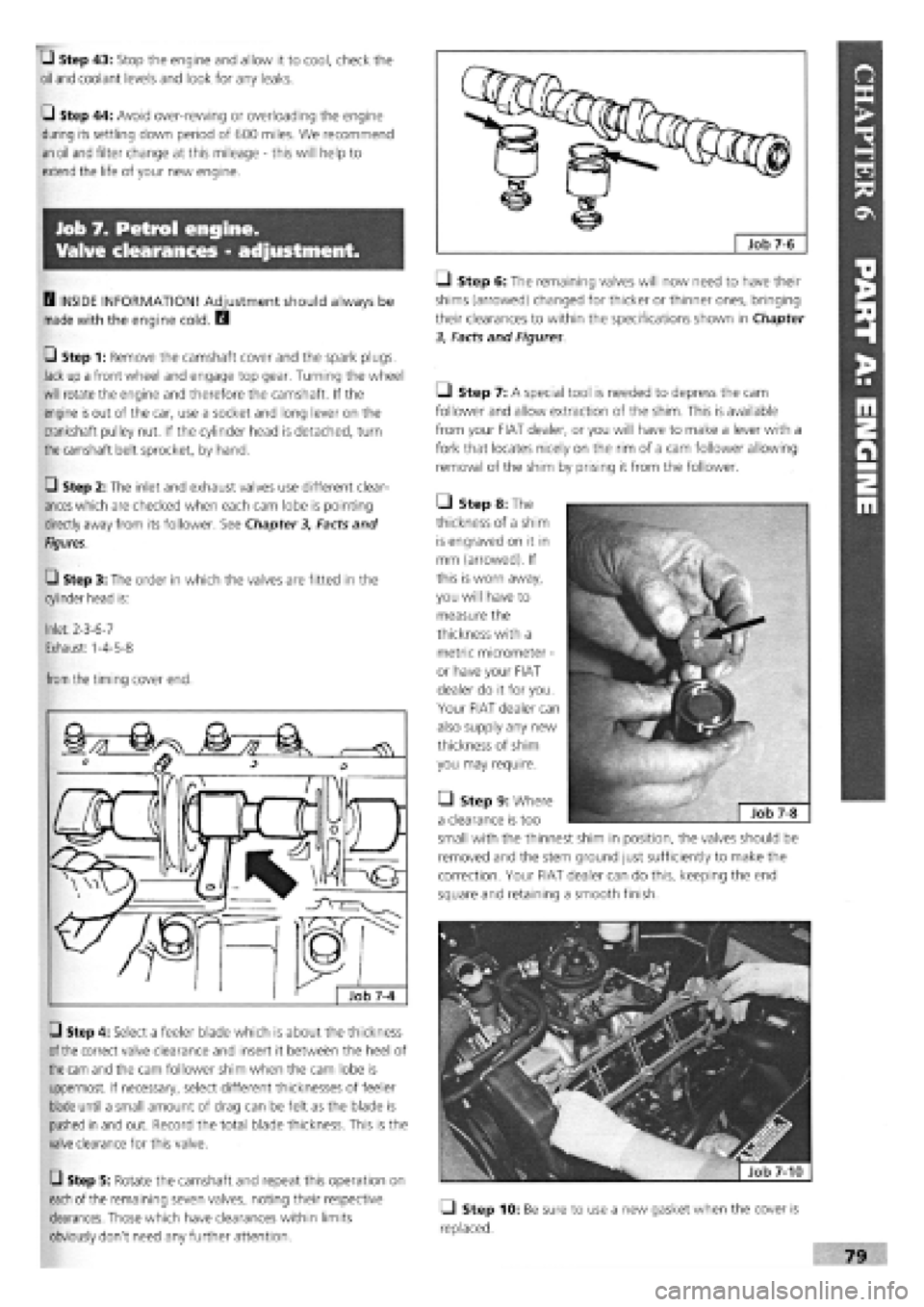
G Step 3: The order in which the valves are fitted in the
cylinder head is:
Inlet: 2-3-6-7
Exhaust: 1-4-5-8
from
the timing cover end.
G Step 4: Select a feeler blade which is about the thickness
of the
correct valve clearance and insert it between the heel of
the cam
and the cam follower shim when the cam lobe is
uppermost. If necessary, select different thicknesses of feeler
blade until a small amount of drag can be felt as the blade is
pushed in and out. Record the total blade thickness. This is the
valve clearance for this valve.
G Step 5: Rotate the camshaft and repeat this operation on
each
of the remaining seven valves, noting their respective
clearances. Those which have clearances within limits
obviously don't need any further attention.
Q Step 6: The remaining valves will now need to have their
shims (arrowed) changed for thicker or thinner ones, bringing
their clearances to within the specifications shown in Chapter
3, Facts and Figures
Ll Step 7: A special tool is needed to depress the cam
follower and allow extraction of the shim. This is available
from your FIAT dealer, or you will have to make a lever with a
fork that locates nicely on the rim of a cam follower allowing
removal of the shim by prising it from the follower.
• Step 8: The
thickness of a shim
is engraved on it in
mm (arrowed). If
this is worn away,
you will have to
measure the
thickness with a
metric micrometer
-
or have your FIAT
dealer do it for you.
Your FIAT dealer can
also supply any new
thickness of shim
you may require.
• Step 9: Where
a clearance is too
small with the thinnest shim in position, the valves should be
removed and the stem ground just sufficiently to make the
correction. Your FIAT dealer can do this, keeping the end
square and retaining a smooth finish.
fjfefe^ | Job 7-10
Q Step 10: Be sure to use a new gasket when the cover is
replaced.
Page 116 of 171
over stop and will also reach its 'maximum speed' stop with
the pedal fully depressed.
Job 8. Mechanical fuel pump,
petrol engine (carburettored) -
replacement.
O Step 1: Disconnect the battery earth lead.
• Step 2: Find the pump on the forward facing side of the
cylinder block near the timing cover end. Disconnect the two
fuel lines from the pump and plug the ends, (labelling them
for correct refitment).
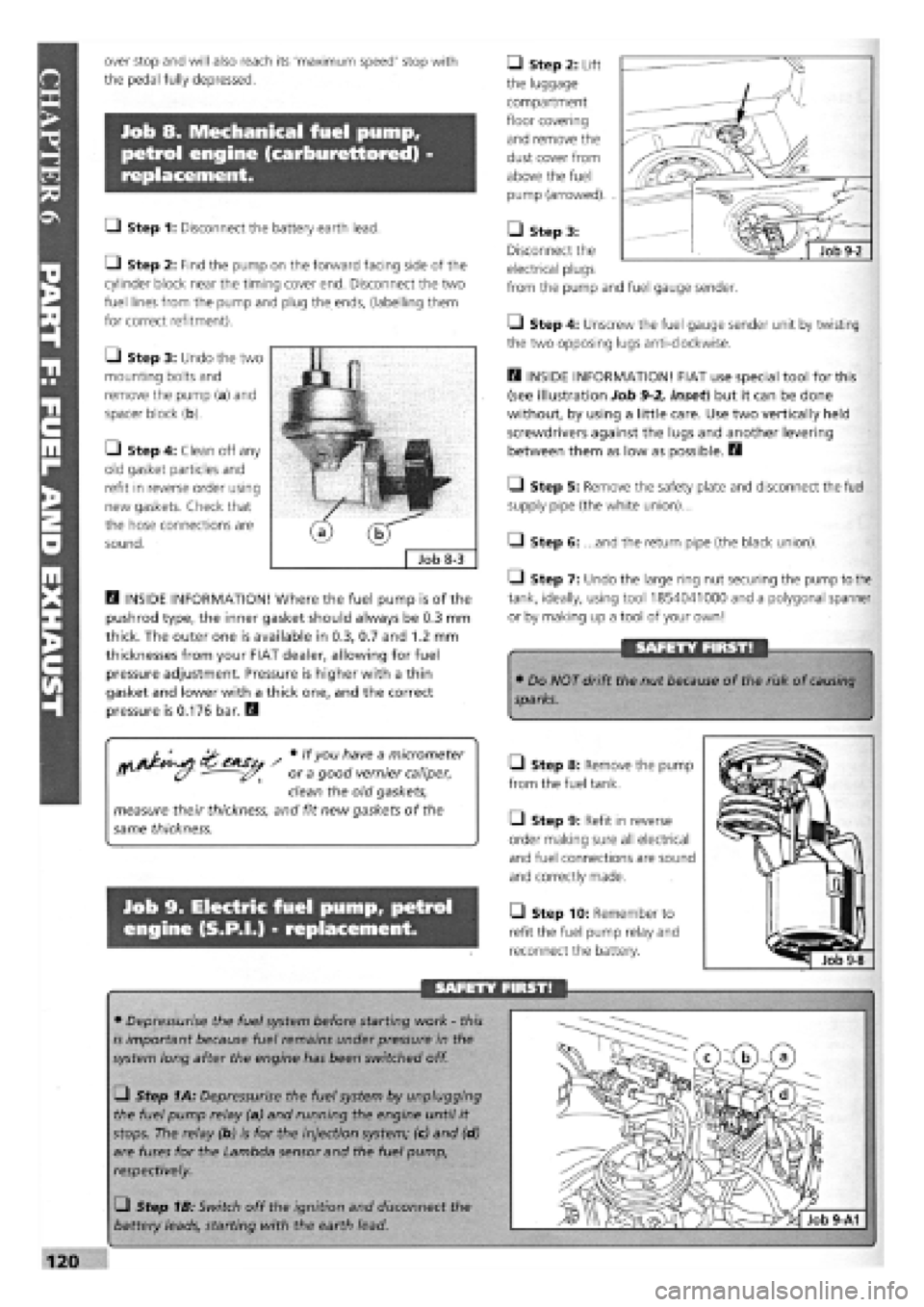
• Step 3: Undo the two
mounting bolts and
remove the pump (a) and
spacer block (b).
• Step 4: Clean off any
old gasket particles and
refit in reverse order using
new gaskets. Check that
the hose connections are
sound.
D INSIDE INFORMATION! Where the fuel pump is of the
pushrod type, the inner gasket should always be 0.3 mm
thick. The outer one is available in 0.3, 0.7 and 1.2 mm
thicknesses from your FIAT dealer, allowing for fuel
pressure adjustment. Pressure is higher with a thin
gasket and lower with a thick one, and the correct
pressure is 0.176 bar. Q
/ # lfyou h"ve a m/cromefer
ff (y - or a good vernier caliper,
clean the old gaskets,
measure their thickness, and fit new gaskets of the
same thickness.
Job 9. Electric fuel pump, petrol
engine (S.P.I.) - replacement.
• Step 2: Lift
the luggage
compartment
floor covering
and remove the
dust cover from
above the fuel
pump (arrowed). .
• Step 3:
Disconnect the
electrical plugs
from the pump and fuel gauge sender.
• Step 4: Unscrew the fuel gauge sender unit by twisting
the two opposing lugs anti-clockwise.
D INSIDE INFORMATION! FIAT use special tool for this
(see illustration Job
9-2,
inset) but it can be done
without, by using a little care. Use two vertically held
screwdrivers against the lugs and another levering
between them as low as possible. H
Q Step 5: Remove the safety plate and disconnect the fuel
supply pipe (the white union)...
Q Step 6: ...and the return pipe (the black union).
1-1 Step 7: Undo the large ring nut securing the pump to the
tank, ideally, using tool 1854041000 and a polygonal spanner
or by making up a tool of your own!
SAFETY FIRST!
• Do NOT drift the nut because of the risk of
causing
sparks.
Q Step 8: Remove the pump
from the fuel tank.
Q Step 9: Refit in reverse
order making sure all electrical
and fuel connections are sound
and correctly made.
• Step 10: Remember to
refit the fuel pump relay and
reconnect the battery.
SAFETY FIRST!
• Depressurise the fuel system before starting work
-
this
is important because fuel remains under pressure in the
system long after the engine has been switched off.
• Step 1A: Depressurise the fuel system by unplugging
the fuel pump relay (a) and running the engine until it
stops. The relay (b) is for the injection system; (c) and (d)
are fuses for the Lambda sensor and the fuel pump,
respectively.
• Step 1B: Switch off the ignition and disconnect the
battery leads, starting with the earth lead.
Page 150 of 171
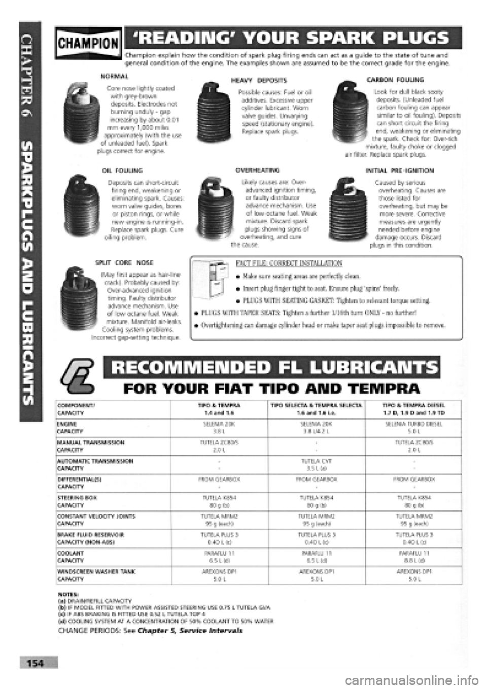
gjpjgjjl 'READING' YOUR SPARK PLUGS
Champion explain how the condition of spark plug firing ends can act as a guide to the state of tune and general condition of the engine. The examples shown are assumed to be the correct grade for the engine.
NORMAL
Core nose lightly coated with grey-brown deposits. Electrodes not burning unduly
-
gap increasing by about 0.01 mm every 1,000 miles approximately (with the use of unleaded fuel). Spark plugs correct for engine.
OIL FOULING
Deposits can short-circuit firing end, weakening or eliminating spark. Causes: worn valve guides, bores or piston rings, or while new engine is running-in. Replace spark plugs. Cure oiling problem.
SPLIT CORE NOSE
(May first appear as hair-line-crack). Probably caused by: Over-advanced ignition timing. Faulty distributor advance mechanism. Use of low octane fuel. Weak mixture. Manifold air-leaks. Cooling system problems. Incorrect gap-setting technique.
HEAVY DEPOSITS
Possible causes: Fuel or oil additives. Excessive upper cylinder lubricant. Worn valve guides. Unvarying speed (stationary engine). Replace spark plugs.
OVERHEATING
Likely causes are: Over-advanced ignition timing, or faulty distributor advance mechanism. Use of low octane fuel. Weak mixture. Discard spark plugs showing signs of overheating, and cure the cause.
CARBON FOULING
Look for dull black sooty deposits. (Unleaded fuel carbon fouling can appear similar to oil fouling). Deposits can short circuit the firing end, weakening or eliminating the spark. Check for: Over-rich mixture, faulty choke or clogged air filter. Replace spark plugs.
INITIAL PRE-IGNITION
Caused by serious overheating. Causes are those listed for overheating, but may be more severe. Corrective measures are urgently needed before engine damage occurs. Discard plugs in this condition.
FACT FILE: CORRECT INSTALLATION
• Make sure seating areas are perfectly clean.
• Insert plug finger tight to seat. Ensure plug 'spins' freely.
• PLUGS WITH SEATING GASKET: Tighten to relevant torque setting.
• PLUGS WITH TAPER SEATS: Tighten a further l/16th turn ONLY - no further!
• Overtightening can damage cylinder head or make taper seat plugs impossible to remove.
RECOMMENDED FL LUBRICANTS
FOR YOUR FIAT TIPO ARID TEMPRA
COMPONENT/ TIPO & TEMPRA TIPO SELECTA & TEMPRA SELECTA TIPO & TEMPRA DIESEL CAPACITY 1.4 and 1.6 1.6 and 1.6 i.e. 1.7 D, 1.9 Dand 1.9 TD
ENGINE SELENIA 20K SELENIA 20K SELENIA TURBO DIESEL CAPACITY 3.8 L 3.8 L/4.2 L 5.0 L
MANUAL TRANSMISSION TUTELA ZC80/S -TUTELA ZC80/S CAPACITY 2.0 L -2.0 L
AUTOMATIC TRANSMISSION -TUTELA CVT -CAPACITY -3.5 L (a) -
DIFFERENTIAL(S) FROM GEARBOX FROM GEARBOX FROM GEARBOX CAPACITY ---
STEERING BOX TUTELA K854 TUTELA K854 TUTELA K854 CAPACITY 80 g (b) 80 g (b) 80 g (b)
CONSTANT VELOCITY JOINTS TUTELA MRM2 TUTELA MRM2 TUTELA MRM2 CAPACITY 95 g (each) 95 g (each) 95 g (each)
BRAKE FLUID RESERVOIR TUTELA PLUS 3 TUTELA PLUS 3 TUTELA PLUS 3 CAPACITY (NON-ABS) 0.40
L
(c) 0.40 L (c) 0.40
L
(c)
COOLANT PARAFLU 11 PARAFLU 11 PARAFLU 11 CAPACITY 6.5 L(d) 6.5 L(d) 8.8
L
(d)
WINDSCREEN WASHER TANK AREXONS DP1 AREXONS DP1 AREXONS DP1 CAPACITY 5.0 L 5.0 L 5.0 L
NOTES: (a) DRAIN/REFILL CAPACITY (b) IF MODEL FITTED WITH POWER ASSISTED STEERING USE 0.75 L TUTELA Gl/A (c) IF ABS BRAKING IS FITTED USE 0.52 L TUTELA TOP 4 (d) COOLING SYSTEM AT A CONCENTRATION OF 50% COOLANT TO 50% WATER
CHANGE PERIODS: See Chapter 5, Service Intervals
154
Page 171 of 171
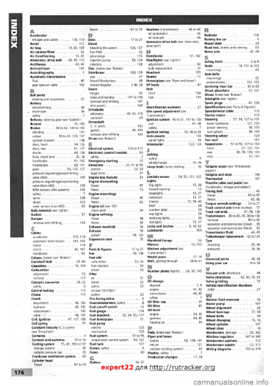
A Accelerator linkages and cables 118,119 Aerial 112 Airbag 14, 63, 128 Air cleaner/filter 51 Air Conditioning 12,41 Alternator, drive belt . . 49, 50, 110 Antifreeze 43, 44 Anti-roll bars 131 Auto-Biography 1 Automatic transmission fluid 45 gear selector cable 102
B Ball-joints steering and suspension 57 Battery disconnecting 36 electrolyte 36 safety 7 Bellows, steering gear (see 'Gaiters') Bonnet 15, 143 Brakes 59 to 62, 134 to 142 bleeding 141 caliper 59 to 61, 135, 137 cylinder (master) 138 discs, front 59, 135 discs, rear 61, 137 drums 60, 136 fluid, check level 35,36 handbrake 61, 142 hoses/pipes 62, 141 pads 59, 135, 137 pressure regulating/proportioning . . . valve (ABS) 140 pressure regulating/proportioning valve (Non-ABS) 139 RPM sensors (ABS systems) .... 140 safety 7 servo 138 shoes 135 wear sensors (non-ABS) 60 Bulb renewal (see 'Lights') Bushes 57 Bumper removal and refitting. 146
c Cables accelerator 118,119 automatic transmission ... 101, 102 choke 119 clutch 46, 101 handbrake 61 Caliper, brakes (see 'Brakes') Camshaft belt 43, 66 Capacities 19,154 Carburettor adjustment 53 removal 117 Catalytic converter 54, 55 safety 6 Central locking 114 Choke 119 Clutch adjustment 46, 100 hydraulic 46, 105 replacement 100 cable 46, 101 Coil, ignition 47, 107, 108 Coil spring 57 Constant Velocity (C.V.) joints (see 'Driveshaft') Contents 4 Controls and switches ... 10 to 14 Cooling system .. 35, 43, 106 to107 change coolant 43 radiator pressure cap 35 Crankcase ventilation system 42 Cylinder head Diesel 87 to 93
Petrol 67 to 73
D Data 17 to 27 Diesel bleeding the system 126,127 fuel filter 52 glow plugs 115 injection pump 56,124 injectors 126 Disc, brakes (see 'Brakes') Distributor 108, 109 cap 47 Marelli Breakerless 48 Marelli Digiplex 2 48, 49 Doors hinges 62 locKs and handles 147 to 150 removal and refitting 147 trim panels 146 Drivebelts alternator 49, 50, 110 camshaft 43 Driveshaft C.V. joints 103 gaiters 45, 103 removal and refitting 103 Drum (see 'Brakes')
E Electrical system 110 to 115 Electronic control module 54 safety 7 Emergency starting 16 Emissions 31, 51 to 56 control 53, 54 legal limits 31 Engine bay layouts 34 Engine dismantling Diesel 95 Petrol 73 Engine mountings Diesel 95 Petrol 83 Engine oil (see 'Oil') check level 34 Engine refitting Diesel 94 Petrol 82 Exhaust manifold 56 Exhaust 56 system 56, 122 Expansion tank 35
F Facts & Figures 17 to 27 Fan 50, 106 Fast idle carburettor 53, 54 fuel injection 54 diesel 55 Filter air 51 diesel 52 petrol 52 oil (see 'Oil filter') pollen 63 Fire Extinguisher . 6 Fluoroelastomers, safety 8 Fuel cut-off switch 13 Fuel gauge 114 Fuel injection 52, 54, 55, 117 Fuel lines/pipes 51 Fuel pump electric 120 mechanical 120 Fuel system 51 to 56 evaporation control system . 54,122 Fuel tank 121 Fumes, safety 6 Fuses 40
Gearbox (transmission) .... 44 to 46 oil (automatic) . . 45 oil (manual) 44 Generator drive belt (see 'Alternator, drive belt')
H Handbrake 61, 142 Headlights (see 'Lights') adjustment 62 bulb replacement 37 Headrest 153 Heater 11 Hoses/pipes (see 'Pipes and hoses') HT leads 47 Hub front 104 rear 134
I Identification numbers 27 Idle speed adjustment (see 'Carburettor') Ignition system 46 to 51, 107 to 109 coil 47,48 safety 7 Ignition timing 19, 48 to 50 Instruments 110 panel lights 10 Intercooler 123, 124
J Jacking safety 5 wheelchange 15, 16 Jump leads (Jump starting) 16
L Lambda sensor ... 54, 55, 121, 122 Lights fog lights 13, 38 hazard warning 13 headlights 13,37 indicators 13, 37 interior 15, 39, 40 MoT 28 number plate 39 rear lights 38 reversing lights 39 sidelights 13, 37 Locks and latches 9, 10, 62 Lubricants 154
m Manifold fixings 56 Mirrors 14, 150 Mixture adjustment (see 'Carburettor') Model years 17, 18 MoT, getting through 28 to 31
m Number plates (lights) . . 28, 39, 145
o Oil change disposal 7, 8 engine 41, 42 transmission 44, 45 safety 7 Oil filler cap 35 Oil filter 41 Oil level engine 34, 35 gearbox 44, 45 topping up 35
P-Pads, brake (see 'Brakes') Pipes and hoses brakes 62, 138, 141 hot air 121 radiator (cooling system) 43 Plastics, safety 7 Production changes 17, 18
ft Radiator .* 106 Raising the car 5 Repair data 20 Road test, brakes and steering ... 63 Rotor arm 47, 49
s Safety First! 5 to 8 Seats 14, 151 to 153 mountings 62 Seat belts mountings 62 pretensioners 151, 152 Servicing Your Car 32 to 63 Shock absorbers 57,131 Shoes, brake (see 'Brakes') Sidelights (see 'Lights') Spark plugs 47, 154 Specifications (see 'Facts & Figures') Speedometer cable 110 Starter motor 110 Steering 57, 58, 127 to 131 lower wishbone 127, 130 power steering 58, 130 rack gaiters 58, 133 Steering wheel 128 Sun roof 151 Suspension ... 57 to 59, 127 to 134 front 57, 127, 131 rear 58, 59, 128, 133 strut 57, 131
T Tailgate wiper (see 'Windscreen wipers') Tailgate and strut 144 Thermostat 107 Throttle cable and pedal (see 'Accelerator, linkage and cables') Timing belt 43 Diesel 85 to 87 Petrol 65, 66 Torque wrench settings ... 23 to 27 Track control arm (inner bushes). . 57 Track rod ends 57, 58, 128 Transmission. . 80 to 83, 95, 98 to 106 removal 80 to 82 separation and reconnection (Diesel). . 95 separation and reconnection (Petrol). . 83 Transmission fluid 44, 45 Turbocharger replacement 122 to 124 Tyre checking 30, 36 pressures 18,36
u Universal joints 28, 58 Using your car 9 to 16
¥ Vacuum unit, distributor 48 Valve clearances 42, 43, 79, 93 Valve grinding 72 Vehicle Identification Numbers (VIN) 27
w Washer fluid reservoir 36 Water pump 107 Wheel alignment 28 Wheel bearings 57, 58 Wheel bolts 59 Wheel changing 15,16 Wheel cylinder 137 Wheel sizes 18 Windscreen, damage 29,162 Window regulator 147 to 149 Windscreen washers 112 Windscreen wipers 13,111 Wiring diagrams 155 to 174
Gaiters 30, 57
expert22 fl/ia http://rutracker.org