engine FIAT TIPO 4DOORS 2018 Owner handbook (in English)
[x] Cancel search | Manufacturer: FIAT, Model Year: 2018, Model line: TIPO 4DOORS, Model: FIAT TIPO 4DOORS 2018Pages: 244, PDF Size: 5.77 MB
Page 120 of 244
The flap is provided with a dust cover
gaiter 2 which prevents deposits of
impurities and dust at the end of the
filler when the flap is closed.
Emergency refuelling
If there is no fuel in the vehicle or the
supply circuit is completely empty,
proceed as follows to reintroduce fuel
to the tank:
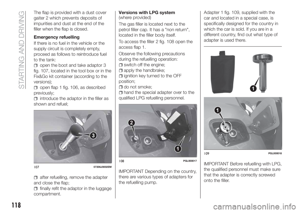
open the boot and take adaptor 3
fig. 107, located in the tool box or in the
Fix&Go kit container (according to the
versions);
open flap 1 fig. 106, as described
previously;
introduce the adaptor in the filler as
shown and refuel;
after refuelling, remove the adapter
and close the flap;
finally refit the adaptor in the luggage
compartment.Versions with LPG system
(where provided)
The gas filler is located next to the
petrol filler cap. It has a "non return",
located in the filler body itself.
To access the filler 2 fig. 108 open the
access flap 1.
Observe the following precautions
during the refuelling operation:
switch off the engine;
apply the handbrake;
ignition key turned to the OFF
position;
do not smoke;
hand the special adapter over to the
qualified LPG refuelling personnel.
IMPORTANT Depending on the country,
there are various types of adapters for
the refuelling pump.Adapter 1 fig. 109, supplied with the
car and located in a special case, is
specifically designed for the country in
which the car is sold. If you are in a
different country, find out what type of
adapter is used there.
IMPORTANT Before refuelling with LPG,
the qualified personnel must make sure
that the adapter is correctly screwed
onto the filler.10707206J0002EM
108PGL000017
109PGL000018
118
STARTING AND DRIVING
Page 121 of 244

IMPORTANT Look after the LPG
adapter carefully so that it does not get
damaged.
IMPORTANT Only use LPG for motor
vehicles.
Fuel - Vehicle
compatibility
identification Graphic
symbol for informing
consumers in
accordance with
EN16942
The symbols shown below facilitated
recognising the correct fuel type to be
used on your car.
Before proceeding with refuelling, check
the symbols inside the fuel filler flap
(where provided) and compare them
with the symbols shown on the fuel
pump (where provided).
Symbols for petrol powered cars
E5: Unleaded petrol containing up to
2.7% (m/m) oxygen and with maximum
5.0% (V/V) ethanol compliant with
EN228E10: Unleaded petrol containing up to
3.7% (m/m) oxygen and with maximum
10.0% (V/V) ethanol compliant with
EN228
Symbols for diesel powered cars
B7: Diesel containing up to 7% (V/V) of
FAME (Fatty Acid Methyl Esters)
compliant with theEN590specification
B10: Diesel containing up to 10% (V/V)
of FAME (Fatty Acid Methyl Esters)
compliant with theEN16734
specification
Symbols for petrol/LPG bi-fuel cars
E5: Unleaded petrol containing up to
2.7% (m/m) oxygen and with maximum
5.0% (V/V) ethanol compliant with
EN228
E10: Unleaded petrol containing up to
3.7% (m/m) oxygen and with maximum
10.0% (V/V) ethanol compliant with
EN228LPG: Automotive LPG compliant with
EN589
WARNING
124)Do not apply any object/plug to the
end of the filler which is not provided for
the car. The use of non-compliant
objects/plugs could cause a pressure
increase inside the tank, resulting in
dangerous situations.
125)Do not bring naked flames or lit
cigarettes near to the fuel filler: fire risk.
Keep your face away from the fuel filler to
prevent breathing in harmful vapours.
126)Do not use a mobile phone near the
refuelling pump: risk of fire.
IMPORTANT
48)For diesel engines, only use diesel fuel
for motor vehicles in accordance with EN
590 European specifications. The use of
other products or mixtures may damage
the engine beyond repair and consequently
invalidate the warranty, due to the damage
caused. If you accidentally introduce other
types of fuel into the tank, do not start the
engine. Empty the tank. If the engine has
been run for even an extremely limited
amount of time, you must not only drain the
fuel tank, but the rest of the supply circuit
as well.
119
Page 126 of 244

REPLACING AN
EXTERNAL BULB
Front bulb position
1. Dipped headlights
2. Fog lights
3. Main beam headlights/Daytime
running lights (DRL)
4. Direction indicator.
Dipped beam headlights
Right headlight
To replace the bulb 1 fig. 111, proceed
as follows:
steer the car wheels completely
inwards;
undo screw 1 fig. 112 using the
screwdriver provided and remove
inspection flap 2;
remove the rubber cap
disconnect the electrical connector;
extract the bulb, releasing it from the
retaining springs;
replace the new bulb and carry out
the procedure described previously in
reverse.
Left headlight
working from inside the engine
compartment, remove the rubber cap
from the dipped beam headlight bulb 1
fig. 111;
extract the bulb, releasing it from the
retaining springs;
disconnect the electrical connector
and replace the bulb 1 fig. 111;
reconnect the electrical connector to
the new bulb;
reposition the assembly in the seat;
refit the rubber cap.
IMPORTANT Only replace the bulb
when the engine is off. Also ensure that
the engine is cold, to prevent the risk of
burns.
Fog lights
To replace the bulbs, proceed as
follows:
11108026J0002EM
112P08026J004
113P08026J0012
124
IN AN EMERGENCY
Page 127 of 244
steer the car wheels completely
inwards;
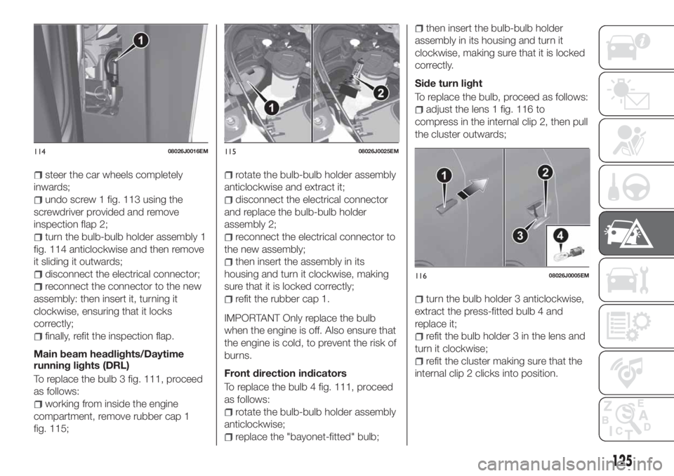
undo screw 1 fig. 113 using the
screwdriver provided and remove
inspection flap 2;
turn the bulb-bulb holder assembly 1
fig. 114 anticlockwise and then remove
it sliding it outwards;
disconnect the electrical connector;
reconnect the connector to the new
assembly: then insert it, turning it
clockwise, ensuring that it locks
correctly;
finally, refit the inspection flap.
Main beam headlights/Daytime
running lights (DRL)
To replace the bulb 3 fig. 111, proceed
as follows:
working from inside the engine
compartment, remove rubber cap 1
fig. 115;
rotate the bulb-bulb holder assembly
anticlockwise and extract it;
disconnect the electrical connector
and replace the bulb-bulb holder
assembly 2;
reconnect the electrical connector to
the new assembly;
then insert the assembly in its
housing and turn it clockwise, making
sure that it is locked correctly;
refit the rubber cap 1.
IMPORTANT Only replace the bulb
when the engine is off. Also ensure that
the engine is cold, to prevent the risk of
burns.
Front direction indicators
To replace the bulb 4 fig. 111, proceed
as follows:
rotate the bulb-bulb holder assembly
anticlockwise;
replace the "bayonet-fitted" bulb;
then insert the bulb-bulb holder
assembly in its housing and turn it
clockwise, making sure that it is locked
correctly.
Side turn light
To replace the bulb, proceed as follows:
adjust the lens 1 fig. 116 to
compress in the internal clip 2, then pull
the cluster outwards;
turn the bulb holder 3 anticlockwise,
extract the press-fitted bulb 4 and
replace it;
refit the bulb holder 3 in the lens and
turn it clockwise;
refit the cluster making sure that the
internal clip 2 clicks into position.
11408026J0016EM11508026J0025EM
11608026J0005EM
125
Page 130 of 244

WARNING
127)Before replacing the bulb, wait for the
exhaust ducts to cool down: DANGER OF
SCALDING!
128)Modifications or repairs to the electric
system that are not carried out properly or
do not take the system technical
specifications into account can cause
malfunctions leading to the risk of fire.
129)Halogen bulbs contain pressurised
gas, in the case of breakage they may
burst causing glass fragments to be
projected outwards.
130)Only replace the light bulbs when the
engine is off and in a position that does not
interfere with traffic and lets you safely
replace them (see the description in the
“Replacement” paragraph). Also ensure
that the engine is cold, to prevent the risk
of burns.
IMPORTANT
49)Halogen bulbs must be handled
holding the metallic part only. Touching the
transparent part of the bulb with your
fingers may reduce the intensity of the
emitted light and even reduce the lifespan
of the bulb. In the event of accidental
contact, wipe the bulb with a cloth
moistened with alcohol and let the bulb dry.
REPLACING FUSES
GENERAL INFORMATION
131) 132) 133) 134)
50)
Fuses protect the electrical system:
they intervene (blow) in the event of a
failure or improper action on the
system.
Fuse extracting pliers
To replace a fuse, use the pliers hooked
inside the engine compartment fuse
box cover (see fig. 127 ).
The pliers have two different ends,
specifically designed to remove the
different types of fuses present in the
vehicle.
After use, refit the pliers in position.
FUSE LOCATION
The fuses are grouped in three control
units: on the dashboard, in the engine
compartment and inside the boot.
12708036J0002EM
128
IN AN EMERGENCY
Page 131 of 244
ENGINE COMPARTMENT
CONTROL UNIT
51)
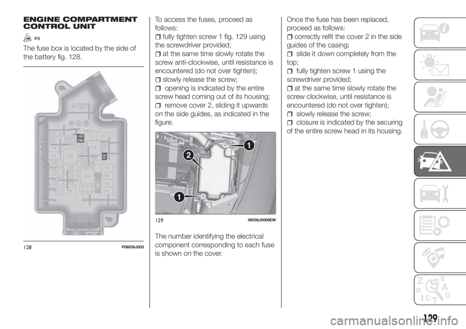
The fuse box is located by the side of
the battery fig. 128.To access the fuses, proceed as
follows:
fully tighten screw 1 fig. 129 using
the screwdriver provided;
at the same time slowly rotate the
screw anti-clockwise, until resistance is
encountered (do not over tighten);
slowly release the screw;
opening is indicated by the entire
screw head coming out of its housing;
remove cover 2, sliding it upwards
on the side guides, as indicated in the
figure.
The number identifying the electrical
component corresponding to each fuse
is shown on the cover.Once the fuse has been replaced,
proceed as follows:
correctly refit the cover 2 in the side
guides of the casing;
slide it down completely from the
top;
fully tighten screw 1 using the
screwdriver provided;
at the same time slowly rotate the
screw clockwise, until resistance is
encountered (do not over tighten);
slowly release the screw;
closure is indicated by the securing
of the entire screw head in its housing.
128P08036J003
12908036J0006EM
129
Page 134 of 244
ENGINE COMPARTMENT FUSE BOX
USERSFUSE AMPERE
Two-tone horn F10 15
Heater mirrors F88 7.5
Heated rear window F20 30
DASHBOARD FUSE BOX
USERSFUSE AMPERE
Front electric window (driver side) F47 25
Front electric window (passenger side) F48 25
Supply forUconnect
™system, Climate Control system, EOBD
system, USB/AUX port (where provided), steering wheel
controls.F36 15
Dead Lock device (Driver side door unlocking for
versions/markets, where provided)/Door unlocking/Central
locking/Electric rear flap unlockingF38 20
Windscreen washer pump F43 20
Rear left electric window F33 25
Rear right electric window F34 25
132
IN AN EMERGENCY
Page 135 of 244
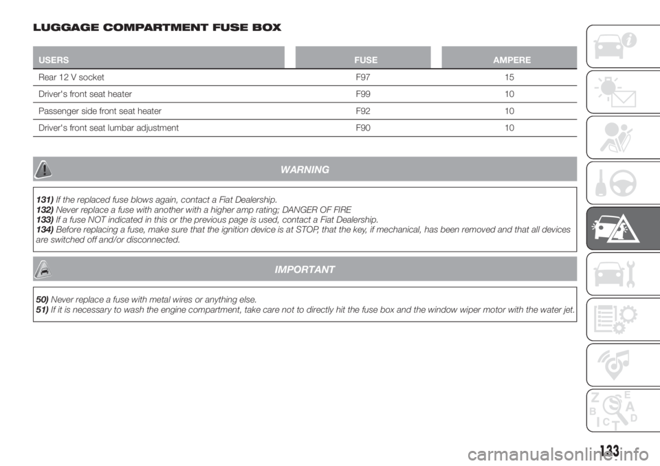
LUGGAGE COMPARTMENT FUSE BOX
USERSFUSE AMPERE
Rear 12 V socket F97 15
Driver's front seat heater F99 10
Passenger side front seat heater F92 10
Driver's front seat lumbar adjustment F90 10
WARNING
131)If the replaced fuse blows again, contact a Fiat Dealership.
132)Never replace a fuse with another with a higher amp rating; DANGER OF FIRE
133)If a fuse NOT indicated in this or the previous page is used, contact a Fiat Dealership.
134)Before replacing a fuse, make sure that the ignition device is at STOP, that the key, if mechanical, has been removed and that all devices
are switched off and/or disconnected.
IMPORTANT
50)Never replace a fuse with metal wires or anything else.
51)If it is necessary to wash the engine compartment, take care not to directly hit the fuse box and the window wiper motor with the water jet.
133
Page 136 of 244
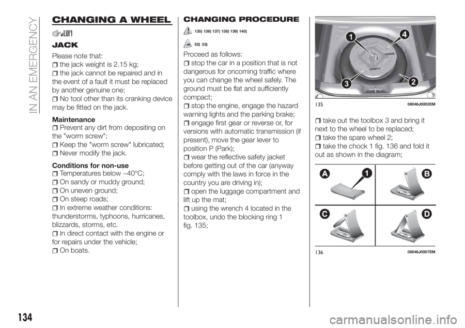
CHANGING A WHEEL
JACK
Please note that:
the jack weight is 2.15 kg;
the jack cannot be repaired and in
the event of a fault it must be replaced
by another genuine one;
No tool other than its cranking device
may be fitted on the jack.
Maintenance
Prevent any dirt from depositing on
the "worm screw";
Keep the "worm screw" lubricated;
Never modify the jack.
Conditions for non-use
Temperatures below −40°C;
On sandy or muddy ground;
On uneven ground;
On steep roads;
In extreme weather conditions:
thunderstorms, typhoons, hurricanes,
blizzards, storms, etc.
In direct contact with the engine or
for repairs under the vehicle;
On boats.
CHANGING PROCEDURE
135) 136) 137) 138) 139) 140)
52) 53)
Proceed as follows:
stop the car in a position that is not
dangerous for oncoming traffic where
you can change the wheel safely. The
ground must be flat and sufficiently
compact;
stop the engine, engage the hazard
warning lights and the parking brake;
engage first gear or reverse or, for
versions with automatic transmission (if
present), move the gear lever to
position P (Park);
wear the reflective safety jacket
before getting out of the car (anyway
comply with the laws in force in the
country you are driving in);
open the luggage compartment and
lift up the mat;
using the wrench 4 located in the
toolbox, undo the blocking ring 1
fig. 135;
take out the toolbox 3 and bring it
next to the wheel to be replaced;
take the spare wheel 2;
take the chock 1 fig. 136 and fold it
out as shown in the diagram;
13508046J0002EM
13608046J0007EM
134
IN AN EMERGENCY
Page 139 of 244
NOTE If replacing a wheel with alloy
rim, stove it temporarily into the spare
wheel compartment with the cosmetic
side facing upwards.
IMPORTANT NOTESTyres with unidirectional tread can be
recognised by arrows on the side of the
tyre which indicate the direction of
rotation. It is compulsory to comply with
this direction. Only in this way can the
tyres maintain their characteristics in
terms of grip, noise, resistance to wear
and drainage on wet surfaces.
If, after a puncture, it is necessary to
fit such a tyre the wrong way round, it
will be necessary to continue driving
with great care, since the tyre’s
performance is limited in these
conditions. This precaution must be
borne in mind above all when the road
surface is wet.
In order to benefit completely from
the unidirectional tread, it is advisable to
restore all wheels to the correct
direction of rotation as soon as
possible.
WARNING
135)If left in the passenger compartment,
the punctured wheel and jack constitute a
serious risk to the safety of occupants in
the event of accidents or sharp braking.
Therefore, always place both the jack and
punctured wheel in the dedicated housing
in the boot.
136)It is extremely dangerous to attempt
to change a wheel on the side of the
vehicle next to the driving lane: make sure
that the vehicle is at a sufficient distance
from the road, to avoid being run over.
137)Alert other drivers that the car is
stationary in compliance with local
regulations: hazard warning lights, warning
triangle, etc. Any passengers on board
should leave the car, especially if it is
heavily laden. Passengers should stay
away from on-coming traffic while the
wheel is being changed. For safety
reasons, always block the wheels with the
chocks provided.138)The jack is a tool developed and
designed only for changing a wheel, if a
tyre gets punctured or damaged, on the
vehicle with which it is supplied or on other
vehicles of the same model. Any other use,
e.g. to jack up other vehicle models or
different things, is strictly prohibited. Never
use it to carry out maintenance or repairs
under the vehicle or to change
summer/winter wheels and vice versa: we
advise you to contact a Fiat Dealership.
Never go under the raised vehicle: use it
only in the positions indicated. Do not use
the jack for loads higher than the one
shown on its label. Never start the engine
with vehicle raised. If the vehicle is raised
more than necessary, everything can
become more unstable, with the risk of the
vehicle dropping violently. Thus, lift the car
only as needed in order to access the
spare wheel.
139)Never tamper with the inflation valve.
Never introduce tools of any kind between
the rim and the tyre. Check tyre and
space-saver wheel pressures regularly,
complying with the values given in the
"Technical specifications" chapter.
137