engine FIAT TIPO 4DOORS 2020 Owner handbook (in English)
[x] Cancel search | Manufacturer: FIAT, Model Year: 2020, Model line: TIPO 4DOORS, Model: FIAT TIPO 4DOORS 2020Pages: 252, PDF Size: 7.29 MB
Page 119 of 252
WARNING
121)Parking and other potentially
dangerous manoeuvres are, however,
always the driver’s responsibility. While
carrying out these manoeuvres, always
make sure that no people (especially
children) or animals are in the area
concerned. The camera is an aid for the
driver, but the driver must never allow
his/her attention to lapse during potentially
dangerous manoeuvres, even those
executed at low speeds. Always keep a
slow speed, so as to promptly brake in the
case of obstacles.
IMPORTANT
48)It is vital, for correct operation, that the
camera is always kept clean and free from
any mud, dirt, snow or ice. Be careful not
to scratch or damage the camera while
cleaning it. Avoid using dry, rough or hard
cloths. The camera must be washed using
clean water, with the addition of car
shampoo if necessary. In washing stations
which use steam or high-pressure jets,
clean the camera quickly, keeping the
nozzle more than 10 cm away from the
sensors. Also, do not apply stickers to the
camera.
TOWING TRAILERS
IMPORTANT NOTES
122) 123)
For towing caravans or trailers the
vehicle must be fitted with an approved
tow hook and an adequate electrical
system. Should aftermarket installation
be requested, this must be carried out
by specialists.
Install any specific and/or additional
door mirrors as specified by the
Highway Code.
Remember that, when towing a trailer,
steep hills are harder to climb, braking
distances increase and overtaking takes
longer depending on the overall weight
of the trailer.
Engage a low gear when driving
downhill, rather than constantly using
the brake.
The weight the trailer exerts on the
vehicle tow hook reduces the vehicle's
loading capacity by the same amount.
To make sure that the maximum
towable weight is not exceeded (given
in the vehicle registration document)
account should be taken of the fully
laden trailer, including accessories and
luggage.Do not exceed the speed limits specific
to each country you are driving in, in the
case of vehicles towing trailers. In any
case, the top speed must not exceed
100 km/h.
Any electric brake must be powered
directly by the battery through a cable
with a cross-section of no less than
2.5 mm
2.
In addition to the electrical branches,
the vehicle electrical system can only be
connected to the supply cable for an
electric brake and to the cable for an
internal light for the trailer, not
exceeding 15 W. For connections, use
the preset control unit with a battery
cable with section not less than
2.5 mm
2.
IMPORTANT The use of auxiliary loads
other than external lights (e.g. electric
brake) must take place with engine
running.
INSTALLING A TOW
HOOK
The towing device should be fastened
to the body by specialised personnel
according to any additional and/or
integrative information supplied by the
Manufacturer of the device.
The towing device must meet current
regulations with reference to Directive
94/20/EC and subsequent
amendments.
117
Page 120 of 252
For any version the towing device used
must be right for the towable weight of
the vehicle on which it is to be installed.
For the electrical connection a standard
connector should be used which is
generally placed on a special bracket
normally fastened to the towing device,
and a special ECU for external trailer
light control must be installed on the
vehicle.
Seven or thirteen pin 12 V DC
connections should be used
(CUNA/UNI and ISO/DIN Standards).
Follow any instructions provided by the
vehicle manufacturer and/or the towing
device manufacturer.
WARNING
122)The ABS with which the car is
equipped will not control the braking
system of the trailer. Particular caution is
required on slippery roads.
123)Never modify the braking system of
the vehicle to control the trailer brake. The
trailer braking system must be fully
independent of the car’s hydraulic system.
SUGGESTIONS FOR
DRIVING
SAVING FUEL
Below are some suggestions which
may help you save fuel and thus lower
the amount of harmful emissions
released into the atmosphere.
Vehicle maintenance
Checks and operations should be
carried out in accordance with the
"Scheduled Servicing Plan" (see the
"Maintenance and care" chapter).
Tyres
Check the tyre pressures at least once
every four weeks: if the pressure is too
low, consumption levels increase as
resistance to rolling is higher.
Unnecessary loads
Do not travel with an overloaded
luggage compartment. The weight of
the vehicle and its arrangement greatly
affect fuel consumption and stability.
Roof rack/ski rack
Remove the roof rack or the ski rack
from the roof when they are not used.
These accessories lower aerodynamic
penetration and adversely affect
consumption levels. When transporting
particularly large objects, use a trailer if
possible.Electric devices
Use electrical devices only for the
amount of time needed. The heated
rear window, windscreen wipers and
heater fan require a considerable
amount of energy; increasing the
current uptake increases fuel
consumption (by up to +25% in an
urban cycle).
Climate control system
Using the climate control system will
increase consumption: use standard
ventilation when the temperature
outside permits.
Devices for aerodynamic control
The use of non-certified devices for
aerodynamic control may adversely
affect air drag and consumption levels.
DRIVING STYLE
Starting
Do not warm up the engine at low or
high revs when the vehicle is stationary;
this causes the engine to warm up
more slowly, thereby increasing fuel
consumption and emissions. It is
therefore advisable to move off
immediately, slowly, avoiding high
speeds: in this way the engine will
warm up more quickly.
118
STARTING AND DRIVING
Page 121 of 252
Unnecessary actions
Avoid revving up when starting at traffic
lights or before stopping the engine.
The latter action, as well as
double-declutching, is unnecessary and
causes increased fuel consumption and
pollution.
Gear selection
Use a high gear when traffic and road
conditions allow it. Using a low gear for
faster acceleration will increase fuel
consumption. In the same way,
improper use of a high gear increases
consumption, emissions and engine
wear.
Max. speed
Fuel consumption considerably
increases as speed increases. Maintain
a constant speed, avoiding
unnecessary braking and acceleration,
which cost in terms of both fuel
consumption and emissions.
Acceleration
Accelerating violently severely affects
consumption and emissions:
acceleration should be gradual and
should not exceed the maximum
torque.CONDITIONS OF USE
Cold starting
Short journeys and frequent cold starts
do not allow the engine to reach
optimum operating temperature. This
results in a significant increase in
consumption levels (from +15 to +30%
on the urban cycle) and emissions.
Traffic and road conditions
High fuel consumption is caused by
heavy traffic, for instance when
travelling in a queue with frequent use
of low gears or in cities with many traffic
lights. Winding mountain roads and
rough road surfaces also adversely
affect consumption.
Stops in traffic
During prolonged hold-ups (e.g. level
crossings) switch off the engine.
REFUELLING THE
VEHICLE
124) 125) 126)
Before refuelling, make sure that the
fuel type is correct.
Also stop the engine before refuelling.
PETROL ENGINES
Only use 95 R.O.N. unleaded petrol (EN
228 specifications).
DIESEL ENGINES
49)
Only use Diesel for motor vehicles
(EN590 specification).
When using or parking the vehicle for a
long time in the mountains or cold
areas, it is advisable to refuel using
locally available Diesel. In this case, it is
also advisable to keep the tank over
50% full.
REFUELLING CAPACITY
To ensure that you fill the tank
completely, top up twice after the first
click of the fuel supply gun.
Further top-ups could cause faults in
the fuel feeding system.
119
Page 122 of 252
REFUELLING
PROCEDURE
Diesel and petrol versions
"Capless Fuel" is a device at the
opening for the fuel tank which opens
and re-closes automatically when the
fuel supply gun is introduced/removed.
The "Capless Fuel" device is provided
with an inhibitor which prevents
refuelling with incorrect fuel.
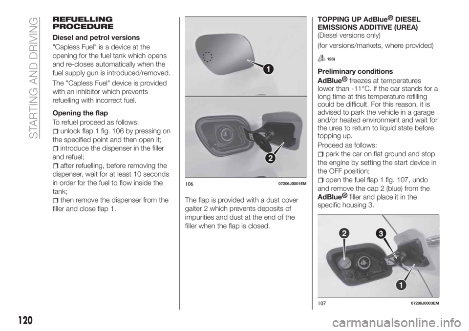
Opening the flap
To refuel proceed as follows:
unlock flap 1 fig. 106 by pressing on
the specified point and then open it;
introduce the dispenser in the filler
and refuel;
after refuelling, before removing the
dispenser, wait for at least 10 seconds
in order for the fuel to flow inside the
tank;
then remove the dispenser from the
filler and close flap 1.The flap is provided with a dust cover
gaiter 2 which prevents deposits of
impurities and dust at the end of the
filler when the flap is closed.TOPPING UP
AdBlue®
DIESEL
EMISSIONS ADDITIVE (UREA)
(Diesel versions only)
(for versions/markets, where provided)
128)
Preliminary conditions
AdBlue®
freezes at temperatures
lower than -11°C. If the car stands for a
long time at this temperature refilling
could be difficult. For this reason, it is
advised to park the vehicle in a garage
and/or heated environment and wait for
the urea to return to liquid state before
topping up.
Proceed as follows:
park the car on flat ground and stop
the engine by setting the start device in
the OFF position;
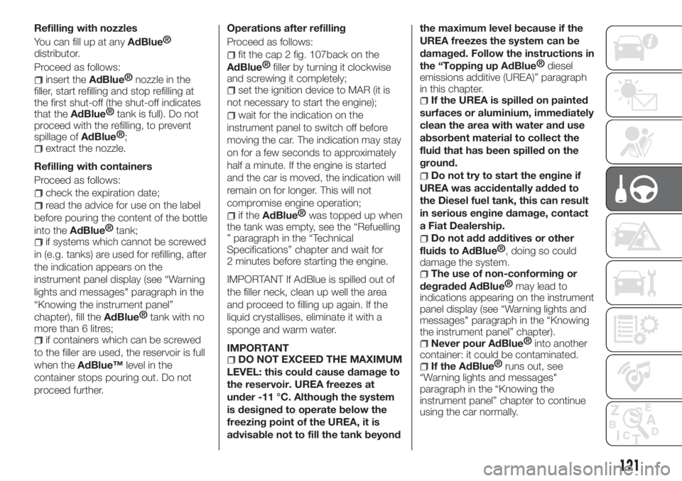
open the fuel flap 1 fig. 107, undo
and remove the cap 2 (blue) from the
AdBlue®
filler and place it in the
specific housing 3.
10607206J0001EM
10707206J0003EM
120
STARTING AND DRIVING
Page 123 of 252
Refilling with nozzles
You can fill up at any
AdBlue®
distributor.
Proceed as follows:
insert theAdBlue®
nozzle in the
filler, start refilling and stop refilling at
the first shut-off (the shut-off indicates
that the
AdBlue®
tank is full). Do not
proceed with the refilling, to prevent
spillage of
AdBlue®
;
extract the nozzle.
Refilling with containers
Proceed as follows:
check the expiration date;
read the advice for use on the label
before pouring the content of the bottle
into the
AdBlue®
tank;
if systems which cannot be screwed
in (e.g. tanks) are used for refilling, after
the indication appears on the
instrument panel display (see “Warning
lights and messages" paragraph in the
“Knowing the instrument panel”
chapter), fill the
AdBlue®
tank with no
more than 6 litres;
if containers which can be screwed
to the filler are used, the reservoir is full
when theAdBlue™level in the
container stops pouring out. Do not
proceed further.Operations after refilling
Proceed as follows:
fit the cap 2 fig. 107back on the
AdBlue®
filler by turning it clockwise
and screwing it completely;
set the ignition device to MAR (it is
not necessary to start the engine);
wait for the indication on the
instrument panel to switch off before
moving the car. The indication may stay
on for a few seconds to approximately
half a minute. If the engine is started
and the car is moved, the indication will
remain on for longer. This will not
compromise engine operation;
if theAdBlue®
was topped up when
the tank was empty, see the “Refuelling
” paragraph in the “Technical
Specifications” chapter and wait for
2 minutes before starting the engine.
IMPORTANT If AdBlue is spilled out of
the filler neck, clean up well the area
and proceed to filling up again. If the
liquid crystallises, eliminate it with a
sponge and warm water.
IMPORTANTDO NOT EXCEED THE MAXIMUM
LEVEL: this could cause damage to
the reservoir. UREA freezes at
under -11 °C. Although the system
is designed to operate below the
freezing point of the UREA, it is
advisable not to fill the tank beyondthe maximum level because if the
UREA freezes the system can be
damaged. Follow the instructions in
the “Topping up
AdBlue®
diesel
emissions additive (UREA)” paragraph
in this chapter.
If the UREA is spilled on painted
surfaces or aluminium, immediately
clean the area with water and use
absorbent material to collect the
fluid that has been spilled on the
ground.
Do not try to start the engine if
UREA was accidentally added to
the Diesel fuel tank, this can result
in serious engine damage, contact
a Fiat Dealership.
Do not add additives or other
fluids to
AdBlue®
, doing so could
damage the system.
The use of non-conforming or
degraded
AdBlue®
may lead to
indications appearing on the instrument
panel display (see “Warning lights and
messages" paragraph in the “Knowing
the instrument panel” chapter).
Never pourAdBlue®
into another
container: it could be contaminated.
If theAdBlue®
runs out, see
“Warning lights and messages"
paragraph in the “Knowing the
instrument panel” chapter to continue
using the car normally.
121
Page 124 of 252
AdBlue®
(UREA) storage
AdBlue®
(UREA) is considered a very
stable product with a long shelf life.
Stored at temperatures LOWER than
32°C, it has a shelf life of at least one
year.
Follow the instructions on the label of
the container.
Fuel storage - Diesel Fuel
127)
In case of the storage of massive
amounts of fuel, good maintenance is
essential. The fuel contaminated with
water favours the proliferation of
"microbes". These microbes create a
"slime" that can clog the filter system
and fuel pipes. Remove water from the
supply tank and regularly replace the
filter pipe.
NOTE When a Diesel engine runs out
of fuel, air is blown through the fuel
system.
Emergency refuelling
If there is no fuel in the car or the supply
circuit is completely empty, proceed as
follows to reintroduce fuel to the tank:
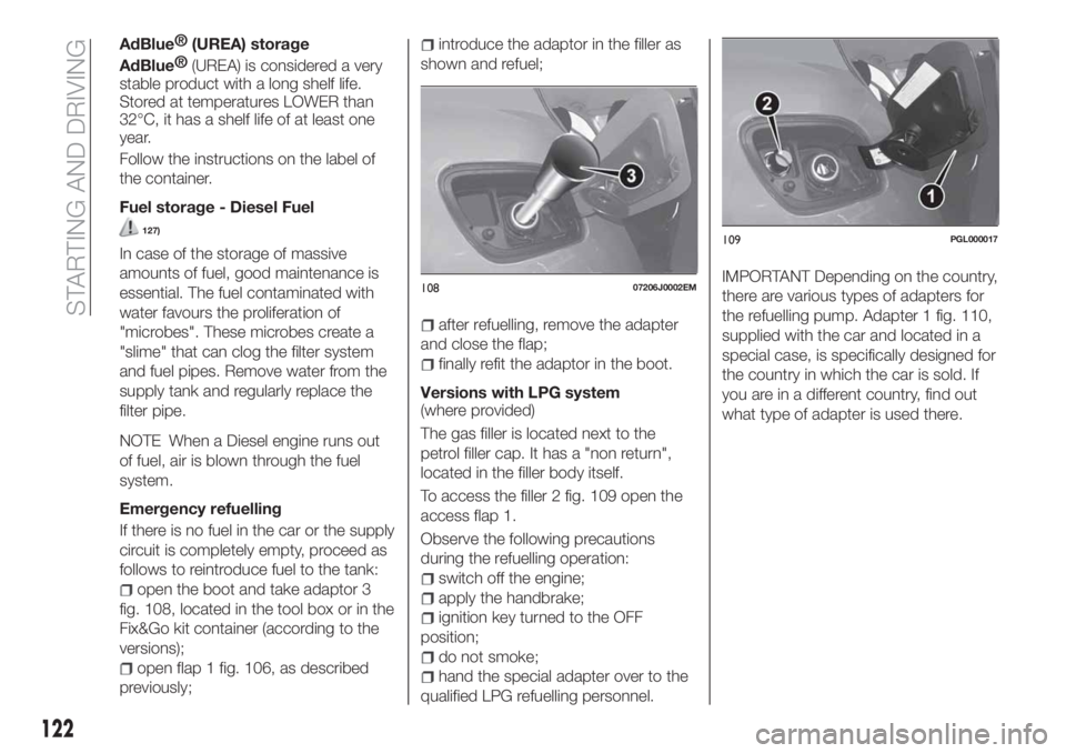
open the boot and take adaptor 3
fig. 108, located in the tool box or in the
Fix&Go kit container (according to the
versions);
open flap 1 fig. 106, as described
previously;
introduce the adaptor in the filler as
shown and refuel;
after refuelling, remove the adapter
and close the flap;
finally refit the adaptor in the boot.
Versions with LPG system
(where provided)
The gas filler is located next to the
petrol filler cap. It has a "non return",
located in the filler body itself.
To access the filler 2 fig. 109 open the
access flap 1.
Observe the following precautions
during the refuelling operation:
switch off the engine;
apply the handbrake;
ignition key turned to the OFF
position;
do not smoke;
hand the special adapter over to the
qualified LPG refuelling personnel.
IMPORTANT Depending on the country,
there are various types of adapters for
the refuelling pump. Adapter 1 fig. 110,
supplied with the car and located in a
special case, is specifically designed for
the country in which the car is sold. If
you are in a different country, find out
what type of adapter is used there.10807206J0002EM
109PGL000017
122
STARTING AND DRIVING
Page 126 of 252
WARNING
124)Do not apply any object/plug to the
end of the filler which is not provided for
the car. The use of non-compliant
objects/plugs could cause a pressure
increase inside the tank, resulting in
dangerous situations.
125)Do not bring naked flames or lit
cigarettes near to the fuel filler: fire risk.
Keep your face away from the fuel filler to
prevent breathing in harmful vapours.
126)Do not use a mobile phone near the
refuelling pump: risk of fire.
127)Do not open the fuel system at high
pressure with the engine running. The
operation of the engine creates a high fuel
pressure. A jet of high-pressure fuel can
cause serious injury or death.
128)If the
AdBlue®
overheats for a
prolonged period inside the tank to over 50
°C (for example, due to direct solar
irradiation), the
AdBlue®
may decompose
and produce ammonia vapours. Ammonia
vapours have a pungent odour when the
cap of the
AdBlue®
tank is unscrewed,
therefore be careful not to inhale any
ammonia vapours in the tank outlet. In this
concentration, however, the ammonia
vapors are not harmful or dangerous to
health.
IMPORTANT
49)For diesel engines, only use diesel fuel
for motor vehicles in accordance with EN
590 European specifications. The use of
other products or mixtures may damage
the engine beyond repair and consequently
invalidate the warranty, due to the damage
caused. If you accidentally introduce other
types of fuel into the tank, do not start the
engine. Empty the tank. If the engine has
been run for even an extremely limited
amount of time, you must not only drain the
fuel tank, but the rest of the supply circuit
as well.
AdBlue®(UREA)
ADDITIVE FOR
DIESEL EMISSIONS
The car is equipped with an UREA
injection system and Selective Catalytic
Reduction to meet emission standards.
These two systems ensure compliance
with the diesel emissions requirements;
at the same, they ensure fuel-efficiency,
handling, torque and power. For
messages and system warnings, refer
to the "Warning lights and messages"
paragraph in the "Knowing the
instrument panel" chapter.
AdBlue®
(UREA) is a very stable
product with a long shelf life. Stored at
temperatures LOWER than 32 °C, it
has a shelf life of at least one year.
For more information on the
AdBlue®
liquid type, see the “Fluids and
lubricants” paragraph in the “Technical
specifications” chapter.
The car is provided with an automatic
AdBlue®
heating system when the
engine starts allowing the system to
work correctly at temperatures lower
than -11 °C.
IMPORTANT
AdBlue®
freezes at
temperatures lower than -11 °C.
124
STARTING AND DRIVING
Page 131 of 252
REPLACING AN
EXTERNAL BULB
Front bulb position
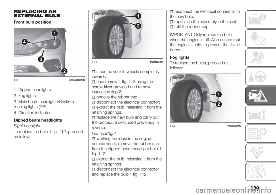
1. Dipped headlights
2. Fog lights
3. Main beam headlights/Daytime
running lights (DRL)
4. Direction indicator.
Dipped beam headlights
Right headlight
To replace the bulb 1 fig. 112, proceed
as follows:
steer the vehicle wheels completely
inwards;
undo screw 1 fig. 113 using the
screwdriver provided and remove
inspection flap 2;
remove the rubber cap
disconnect the electrical connector;
extract the bulb, releasing it from the
retaining springs;
replace the new bulb and carry out
the procedure described previously in
reverse.
Left headlight
working from inside the engine
compartment, remove the rubber cap
from the dipped beam headlight bulb 1
fig. 112;
extract the bulb, releasing it from the
retaining springs;
disconnect the electrical connector
and replace the bulb 1 fig. 112;
reconnect the electrical connector to
the new bulb;
reposition the assembly in the seat;
refit the rubber cap.
IMPORTANT Only replace the bulb
when the engine is off. Also ensure that
the engine is cold, to prevent the risk of
burns.
Fog lights
To replace the bulbs, proceed as
follows:
11208026J0002EM
113P08026J004
114P08026J0012
129
Page 132 of 252
steer the car wheels completely
inwards;
undo screw 1 fig. 114 using the
screwdriver provided and remove
inspection flap 2;
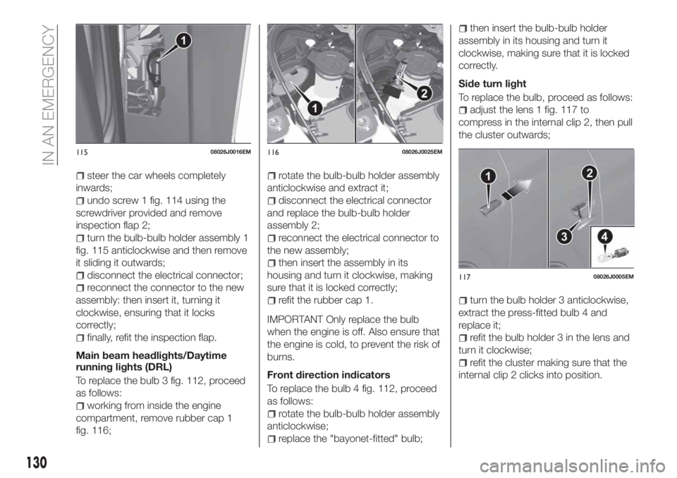
turn the bulb-bulb holder assembly 1
fig. 115 anticlockwise and then remove
it sliding it outwards;
disconnect the electrical connector;
reconnect the connector to the new
assembly: then insert it, turning it
clockwise, ensuring that it locks
correctly;
finally, refit the inspection flap.
Main beam headlights/Daytime
running lights (DRL)
To replace the bulb 3 fig. 112, proceed
as follows:
working from inside the engine
compartment, remove rubber cap 1
fig. 116;
rotate the bulb-bulb holder assembly
anticlockwise and extract it;
disconnect the electrical connector
and replace the bulb-bulb holder
assembly 2;
reconnect the electrical connector to
the new assembly;
then insert the assembly in its
housing and turn it clockwise, making
sure that it is locked correctly;
refit the rubber cap 1.
IMPORTANT Only replace the bulb
when the engine is off. Also ensure that
the engine is cold, to prevent the risk of
burns.
Front direction indicators
To replace the bulb 4 fig. 112, proceed
as follows:
rotate the bulb-bulb holder assembly
anticlockwise;
replace the "bayonet-fitted" bulb;
then insert the bulb-bulb holder
assembly in its housing and turn it
clockwise, making sure that it is locked
correctly.
Side turn light
To replace the bulb, proceed as follows:
adjust the lens 1 fig. 117 to
compress in the internal clip 2, then pull
the cluster outwards;
turn the bulb holder 3 anticlockwise,
extract the press-fitted bulb 4 and
replace it;
refit the bulb holder 3 in the lens and
turn it clockwise;
refit the cluster making sure that the
internal clip 2 clicks into position.
11508026J0016EM11608026J0025EM
11708026J0005EM
130
IN AN EMERGENCY
Page 135 of 252
WARNING
129)Before replacing the bulb, wait for the
exhaust ducts to cool down: DANGER OF
SCALDING!
130)Modifications or repairs to the electric
system that are not carried out properly or
do not take the system technical
specifications into account can cause
malfunctions leading to the risk of fire.
131)Halogen bulbs contain pressurised
gas, in the case of breakage they may
burst causing glass fragments to be
projected outwards.
132)Only replace the light bulbs when the
engine is off and in a position that does not
interfere with traffic and lets you safely
replace them (see the description in the
“Replacement” paragraph). Also ensure
that the engine is cold, to prevent the risk
of burns.
IMPORTANT
50)Halogen bulbs must be handled
holding the metallic part only. Touching the
transparent part of the bulb with your
fingers may reduce the intensity of the
emitted light and even reduce the lifespan
of the bulb. In the event of accidental
contact, wipe the bulb with a cloth
moistened with alcohol and let the bulb dry.
REPLACING FUSES
GENERAL INFORMATION
133) 134) 135) 136)
51)
Fuses protect the electrical system:
they intervene (blow) in the event of a
failure or improper action on the
system.
Fuse extracting pliers
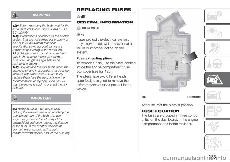
To replace a fuse, use the pliers hooked
inside the engine compartment fuse
box cover (see fig. 128 ).
The pliers have two different ends,
specifically designed to remove the
different types of fuses present in the
vehicle.
After use, refit the pliers in position.
FUSE LOCATION
The fuses are grouped in three control
units: on the dashboard, in the engine
compartment and inside the boot.
12808036J0002EM
133