wheel FIAT TIPO 5DOORS STATION WAGON 2018 Owner handbook (in English)
[x] Cancel search | Manufacturer: FIAT, Model Year: 2018, Model line: TIPO 5DOORS STATION WAGON, Model: FIAT TIPO 5DOORS STATION WAGON 2018Pages: 292, PDF Size: 7.74 MB
Page 108 of 292
SIDE BAGS
To help increase occupants protection
in the event of side impact collisions,
the vehicle is equipped with front side
bags and window bags.
Side bag
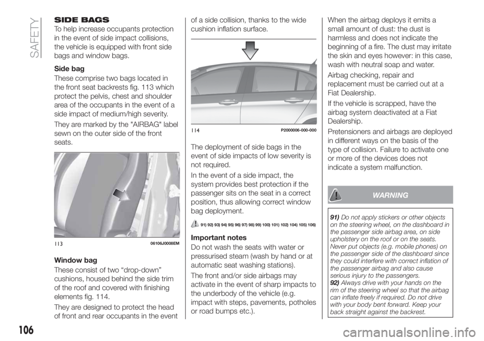
These comprise two bags located in
the front seat backrests fig. 113 which
protect the pelvis, chest and shoulder
area of the occupants in the event of a
side impact of medium/high severity.
They are marked by the "AIRBAG" label
sewn on the outer side of the front
seats.
Window bag
These consist of two “drop-down”
cushions, housed behind the side trim
of the roof and covered with finishing
elements fig. 114.
They are designed to protect the head
of front and rear occupants in the eventof a side collision, thanks to the wide
cushion inflation surface.
The deployment of side bags in the
event of side impacts of low severity is
not required.
In the event of a side impact, the
system provides best protection if the
passenger sits on the seat in a correct
position, thus allowing correct window
bag deployment.
91) 92) 93) 94) 95) 96) 97) 98) 99) 100) 101) 102) 104) 105) 106)
Important notes
Do not wash the seats with water or
pressurised steam (wash by hand or at
automatic seat washing stations).
The front and/or side airbags may
activate in the event of sharp impacts to
the underbody of the vehicle (e.g.
impact with steps, pavements, potholes
or road bumps etc.).When the airbag deploys it emits a
small amount of dust: the dust is
harmless and does not indicate the
beginning of a fire. The dust may irritate
the skin and eyes however: in this case,
wash with neutral soap and water.
Airbag checking, repair and
replacement must be carried out at a
Fiat Dealership.
If the vehicle is scrapped, have the
airbag system deactivated at a Fiat
Dealership.
Pretensioners and airbags are deployed
in different ways on the basis of the
type of collision. Failure to activate one
or more of the devices does not
indicate a system malfunction.
WARNING
91)Do not apply stickers or other objects
on the steering wheel, on the dashboard in
the passenger side airbag area, on side
upholstery on the roof or on the seats.
Never put objects (e.g. mobile phones) on
the passenger side of the dashboard since
they could interfere with correct inflation of
the passenger airbag and also cause
serious injury to the passengers.
92)Always drive with your hands on the
rim of the steering wheel so that the airbag
can inflate freely if required. Do not drive
with your body bent forward. Keep your
back straight against the backrest.
11306106J0008EM
114P2000006-000-000
106
SAFETY
Page 112 of 292
PARKING THE
VEHICLE
When parking and leaving the car,
proceed as follows:
engage a gear (1stgear if facing
uphill or reverse if facing downhill) and
leave the wheels turned;
stop the engine and engage the
handbrake;
always remove the ignition key.
Block the wheels with a wedge or a
stone if the car is parked on a steep
slope.
On versions equipped with automatic
transmission, wait for the letter P to be
displayed before releasing the brake
pedal.
IMPORTANTNEVERleave the car with
the gearbox in neutral (or, on versions
equipped with automatic transmission,
before placing the gear lever at P).
111)
WARNING
111)Never leave children unattended in
the car. Always remove the key from the
ignition when leaving the car and take it
with you.
PARKING BRAKE
112) 113)
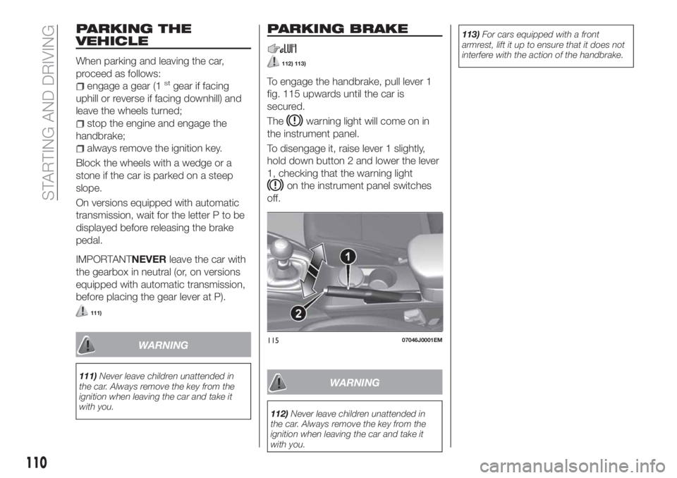
To engage the handbrake, pull lever 1
fig. 115 upwards until the car is
secured.
The
warning light will come on in
the instrument panel.
To disengage it, raise lever 1 slightly,
hold down button 2 and lower the lever
1, checking that the warning light
on the instrument panel switches
off.
WARNING
112)Never leave children unattended in
the car. Always remove the key from the
ignition when leaving the car and take it
with you.113)For cars equipped with a front
armrest, lift it up to ensure that it does not
interfere with the action of the handbrake.
11507046J0001EM
110
STARTING AND DRIVING
Page 114 of 292
The gear engaged is shown on the
display.
To select a gear, move the lever
forwards or backwards.
To select the "sequential" mode, move
the lever from D (Drive) to the left: the
position + (upper gear) or – (lower gear)
can be reached; these are unstable
positions, which means that the lever
always returns to the central position.
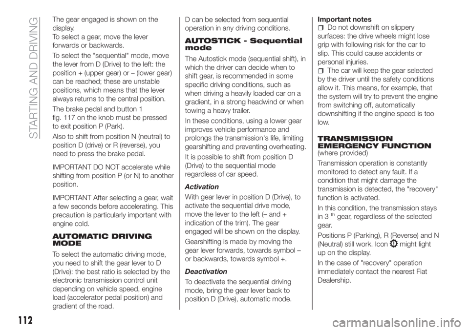
The brake pedal and button 1
fig. 117 on the knob must be pressed
to exit position P (Park).
Also to shift from position N (neutral) to
position D (drive) or R (reverse), you
need to press the brake pedal.
IMPORTANT DO NOT accelerate while
shifting from position P (or N) to another
position.
IMPORTANT After selecting a gear, wait
a few seconds before accelerating. This
precaution is particularly important with
engine cold.
AUTOMATIC DRIVING
MODE
To select the automatic driving mode,
you need to shift the gear lever to D
(Drive): the best ratio is selected by the
electronic transmission control unit
depending on vehicle speed, engine
load (accelerator pedal position) and
gradient of the road.D can be selected from sequential
operation in any driving conditions.
AUTOSTICK - Sequential
mode
The Autostick mode (sequential shift), in
which the driver can decide when to
shift gear, is recommended in some
specific driving conditions, such as
when driving a heavily loaded car on a
gradient, in a strong headwind or when
towing a heavy trailer.
In these conditions, using a lower gear
improves vehicle performance and
prolongs the transmission's life, limiting
gearshifting and preventing overheating.
It is possible to shift from position D
(Drive) to the sequential mode
regardless of car speed.
Activation
With gear lever in position D (Drive), to
activate the sequential drive mode,
move the lever to the left (– and +
indication of the trim). The gear
engaged will be shown on the display.
Gearshifting is made by moving the
gear lever forwards, towards symbol –
or backwards, towards symbol +.
Deactivation
To deactivate the sequential driving
mode, bring the gear lever back to
position D (Drive), automatic mode.Important notes
Do not downshift on slippery
surfaces: the drive wheels might lose
grip with following risk for the car to
slip. This could cause accidents or
personal injuries.
The car will keep the gear selected
by the driver until the safety conditions
allow it. This means, for example, that
the system will try to prevent the engine
from switching off, automatically
downshifting if the engine speed is too
low.
TRANSMISSION
EMERGENCY FUNCTION
(where provided)
Transmission operation is constantly
monitored to detect any fault. If a
condition that might damage the
transmission is detected, the "recovery"
function is activated.
In this condition, the transmission stays
in 3
thgear, regardless of the selected
gear.
Positions P (Parking), R (Reverse) and N
(Neutral) still work. Icon
might light
up on the display.
In the case of "recovery" operation
immediately contact the nearest Fiat
Dealership.
112
STARTING AND DRIVING
Page 117 of 292
Gearshifting is made by moving the
gear lever forwards, towards symbol –
or backwards, towards symbol +.
Deactivation
To deactivate the sequential driving
mode, bring the gear lever back to
position D (Drive), automatic mode.
STARTING THE ENGINE
Engine start-up is allowed only with the
gear lever in P or N position.
Therefore, on starting the engine, the
system will be in the N or P position
(the latter corresponds to neutral, but
with the car wheels mechanically
locked).
MOVING THE CAR
To move the car, from P press the brake
pedal and, using the button on the gear
lever, move the lever to the desired
position (D, R or "Sequential mode").
The display will show the gear engaged.
When the brake pedal is released, the
car starts moving forwards or
backwards, as soon as the manoeuvre
is activated ("creeping" effect). The
accelerator should not be pressed in
this case.
IMPORTANT The inconsistency
between the speed actually engaged
(shown on the display) and the position
of the gear lever is indicated by theletter corresponding to the position of
the gear lever flashing on the panel
(also accompanied by an acoustic
warning). This condition should not be
interpreted as an operational fault, but
simply as a request by the system to
repeat the manoeuvre.
GEAR ENGAGEMENT
DISABLE
This system prevents you from moving
the shift lever from the P (Park) or N
(Neutral) position if you have not
pressed the brake pedal first. With the
start switch in the MAR position (engine
on or off):
to move the shift lever to a position
other than P (Park) or from N to R, you
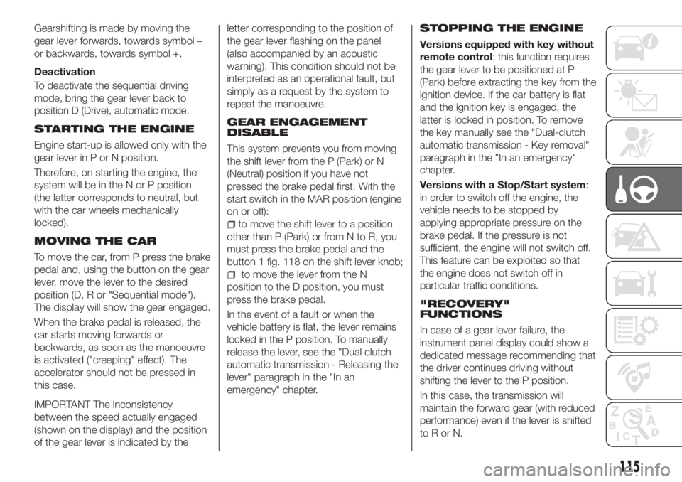
must press the brake pedal and the
button 1 fig. 118 on the shift lever knob;
to move the lever from the N
position to the D position, you must
press the brake pedal.
In the event of a fault or when the
vehicle battery is flat, the lever remains
locked in the P position. To manually
release the lever, see the "Dual clutch
automatic transmission - Releasing the
lever" paragraph in the "In an
emergency" chapter.
STOPPING THE ENGINE
Versions equipped with key without
remote control: this function requires
the gear lever to be positioned at P
(Park) before extracting the key from the
ignition device. If the car battery is flat
and the ignition key is engaged, the
latter is locked in position. To remove
the key manually see the "Dual-clutch
automatic transmission - Key removal"
paragraph in the "In an emergency"
chapter.
Versions with a Stop/Start system:
in order to switch off the engine, the
vehicle needs to be stopped by
applying appropriate pressure on the
brake pedal. If the pressure is not
sufficient, the engine will not switch off.
This feature can be exploited so that
the engine does not switch off in
particular traffic conditions.
"RECOVERY"
FUNCTIONS
In case of a gear lever failure, the
instrument panel display could show a
dedicated message recommending that
the driver continues driving without
shifting the lever to the P position.
In this case, the transmission will
maintain the forward gear (with reduced
performance) even if the lever is shifted
toRorN.
115
Page 120 of 292
SAFETY FUNCTIONS
When the engine is stopped through
the Stop/Start system, if the driver
releases their seat belt or opens the
driver's or passenger's door, the engine
can be restarted only by using the
ignition device.
This condition is indicated to the driver
both through a buzzer and a message
on the display.
"ENERGY SAVING"
FUNCTION
If, following the automatic engine
restarting, the driver does not carry out
any action for more than 3 minutes, the
Stop/Start system stops the engine
definitely, to prevent fuel consumption.
In these cases, the engine can only be
restarted using the ignition device.
NOTE In any case, it is possible to keep
the engine running by deactivating the
system.
IRREGULAR OPERATION
In the event of malfunction, the
Stop/Start system is deactivated.
For failure indications, see the "Warning
lights and messages" paragraph,
"Knowing the instrument panel"
chapter.
VEHICLE INACTIVITY
122)
In the event of vehicle inactivity (or if the
battery is replaced), special attention
must be paid to the disconnection of
the battery power supply.
WARNING
122)If the battery needs to be replaced,
always contact a Fiat Dealership. Replace
the battery with a new one of the same
type and specifications.
IMPORTANT
48)If the climate comfort is to be favoured,
the Start&Stop system can be deactivated,
for a continuous operation of the climate
control system.
SPEED LIMITER
DESCRIPTION
This device allows the speed of the
vehicle to be limited to values which
can be set by the driver.
The maximum speed can be set both
with vehicle stationary and in motion.
The minimum speed that can be set is
30 km/h.
When the device is active, the vehicle
speed depends on the pressure at the
accelerator pedal, until the
programmed speed limit is reached
(see "Speed limit programming"
paragraph).
ACTIVATING THE DEVICE
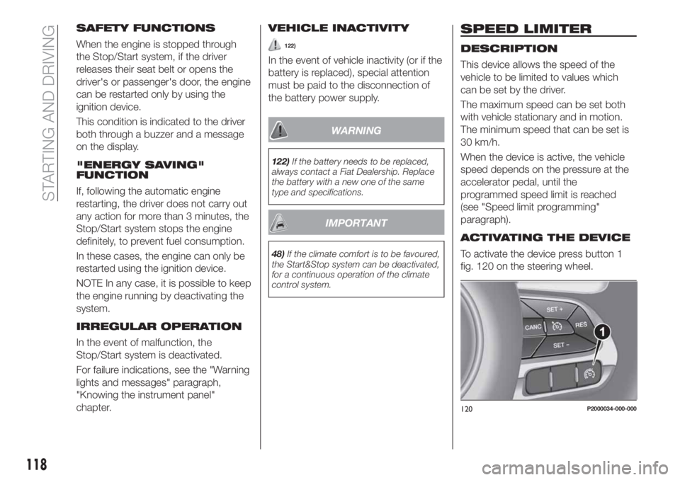
To activate the device press button 1
fig. 120 on the steering wheel.
120P2000034-000-000
118
STARTING AND DRIVING
Page 124 of 292
The device further enhances driving
comfort provided by the electronic
Cruise Control when on the motorway
or out of town with light traffic.
Using the device is not beneficial on
busy extra-urban roads or on urban
streets.
IMPORTANT NOTES
If the sensor does not detect any
vehicle ahead, the device will maintain a
fixed set speed.
If the sensor detects a vehicle ahead,
the device automatically brakes to avoid
getting closer than the set distance.
Once behind a vehicle, the system will
brake or accelerate to maintain the
distance, without ever exceeding the
set speed.
It is advisable to turn the device off in
the following cases:
driving in fog, heavy rain, snow,
heavy traffic and in complex driving
situations (e.g. on motorways with
roadworks in progress);
driving near a bend (winding roads),
icy, snowy, slippery roads or with steep
slopes and descents;
entering a turn lane or on a slip road;
towing a trailer;
when circumstances do not allow
safe driving at a constant speed.There are two operating modes:
“Adaptive Cruise Control” mode
to hold an appropriate distance
between vehicles (a dedicated message
is shown on the instrument panel
display);
electronic “Cruise Control” mode
to hold the vehicle at a constant
preset speed.
To change the operating mode, use the
button on the steering wheel (see that
described on the following pages).
The "electronic Cruise Control" does
not alter the speed if there are vehicles
in front. Always adjust the speed
according to traffic conditions.
ADAPTIVE CRUISE
CONTROL ACTIVATION/
DEACTIVATION
Activation
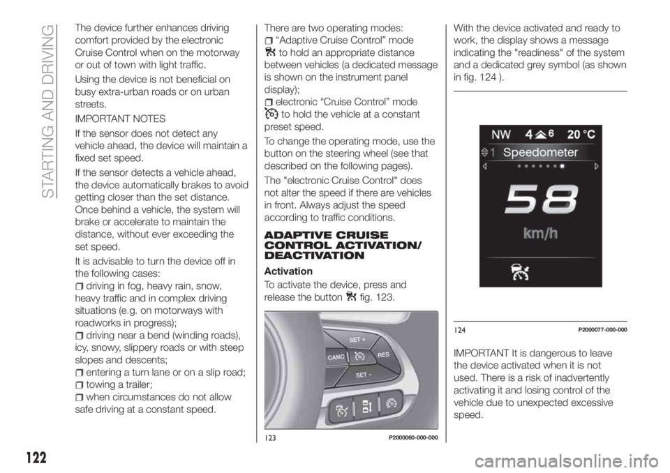
To activate the device, press and
release the button
fig. 123.With the device activated and ready to
work, the display shows a message
indicating the "readiness" of the system
and a dedicated grey symbol (as shown
in fig. 124 ).
IMPORTANT It is dangerous to leave
the device activated when it is not
used. There is a risk of inadvertently
activating it and losing control of the
vehicle due to unexpected excessive
speed.
123P2000060-000-000
124P2000077-000-000
122
STARTING AND DRIVING
Page 134 of 292

SYMBOLS AND MESSAGES ON THE DISPLAY
If activated, using theUconnect™ 5"or7" HDsystem settings, it is possible to activate the guidelines on the display. If
activated, the grid is positioned on the image to highlight the width of the vehicle and the expected reversing path in
accordance with the steering wheel position.
A superimposed central broken line indicates the centre of the vehicle to facilitate parking manoeuvres or tow hook alignment.
The various coloured areas indicate the distance from the rear of the vehicle.
The table below shows the approximate distances for each area fig. 132:
Area Distance from the rear of the vehicle
Red (1) 0–30 cm
Yellow (2) 30–100 cm
Green (3) 1 m or more
132
STARTING AND DRIVING
Page 140 of 292

IN AN EMERGENCY
A punctured tyre or a burnt-out bulb?
At times, a problem may interfere with
our journey.
The pages on emergencies can help
you to deal with critical situations
independently and with calm.
In an emergency we recommend that
you call the freephone number found in
the Warranty Booklet.
It is also possible to call the national or
international universal freephone
number to search for the nearest Fiat
Dealership.HAZARD WARNING LIGHTS.....139
BULB REPLACEMENT.........139
REPLACING FUSES..........148
CHANGING A WHEEL.........155
FIX&GO AUTOMATIC KIT.......159
JUMP STARTING............162
FUEL CUT-OFF SYSTEM.......164
AUTOMATIC TRANSMISSION. . . .166
DUAL-CLUTCH AUTOMATIC
TRANSMISSION............168
TOWING THE VEHICLE........169
138
IN AN EMERGENCY
Page 145 of 292

Front fog lamps
To replace the bulb 2 fig. 138, proceed
as follows:
steer the car wheels inwards;
undo screw 1 fig. 142 using the
screwdriver provided and remove
inspection flap 2;
turn the bulb-bulb holder assembly
3 anticlockwise by a 1/4 turn and
extract it;
disconnect the electrical connector
and replace the complete assembly;
reconnect the electrical connector to
the new bulb-bulb holder assembly;
fit the assembly in its housing,
turning it clockwise and making sure
that it is blocked properly;
finally, refit the inspection flap 1.
Daytime running lights (DRL)
The daytime running light bulbs 4
fig. 138 are LED to increase their
lifetime; therefore, they should not
require replacing. Contact the Fiat
Dealership in the event of any kind of
problem.
Side turn light
To replace the bulb, proceed as follows:
press the lens 1 fig. 143 to compress
in the internal clip 2, then pull the
cluster outwards; take great care not
damage the paintwork;;
turn the bulb holder 2 anticlockwise,
then extract the press-fit bulb 3 and
replace it;
refit the bulb holder 2 in the lens
1 and turn it clockwise;
refit the cluster making sure that the
internal clip clicks into position.Versions with bi-parabolic
headlights
Front bulb position
1. Dipped headlights
2. Fog lights
3. Main beam headlights / Daytime
running lights (DRL)/ Positions
4. Direction indicator.
141P2000185
142P2000135
143P1030251-000-000
14408026J0002EM
143
Page 146 of 292
Main beam headlights / Daytime
running lights (DRL)/ Positions
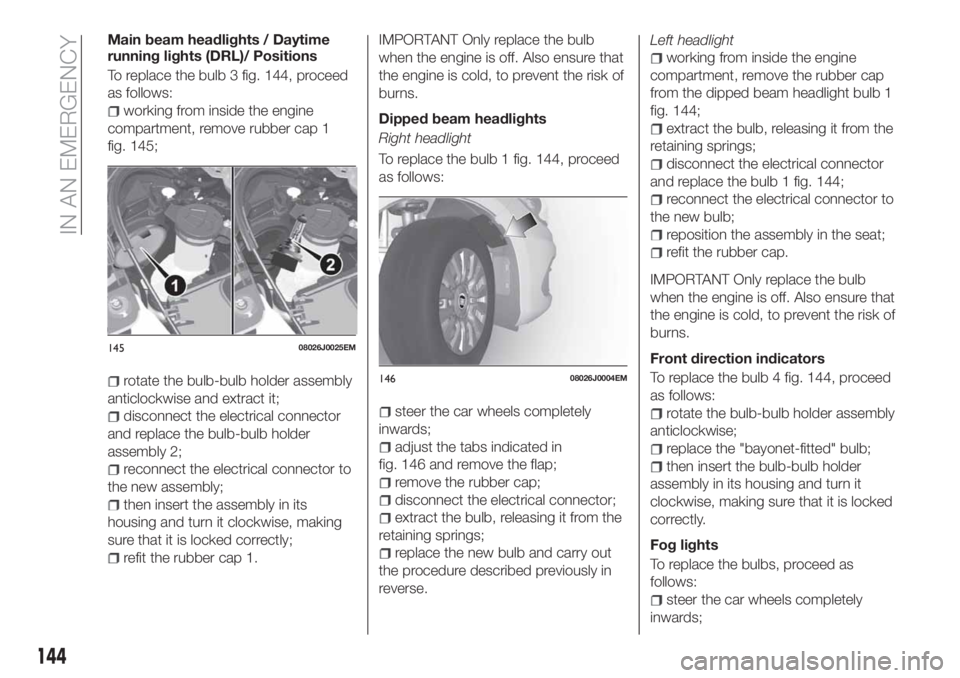
To replace the bulb 3 fig. 144, proceed
as follows:
working from inside the engine
compartment, remove rubber cap 1
fig. 145;
rotate the bulb-bulb holder assembly
anticlockwise and extract it;
disconnect the electrical connector
and replace the bulb-bulb holder
assembly 2;
reconnect the electrical connector to
the new assembly;
then insert the assembly in its
housing and turn it clockwise, making
sure that it is locked correctly;
refit the rubber cap 1.
IMPORTANT Only replace the bulb
when the engine is off. Also ensure that
the engine is cold, to prevent the risk of
burns.
Dipped beam headlights
Right headlight
To replace the bulb 1 fig. 144, proceed
as follows:
steer the car wheels completely
inwards;
adjust the tabs indicated in
fig. 146 and remove the flap;
remove the rubber cap;
disconnect the electrical connector;
extract the bulb, releasing it from the
retaining springs;
replace the new bulb and carry out
the procedure described previously in
reverse.Left headlight
working from inside the engine
compartment, remove the rubber cap
from the dipped beam headlight bulb 1
fig. 144;
extract the bulb, releasing it from the
retaining springs;
disconnect the electrical connector
and replace the bulb 1 fig. 144;
reconnect the electrical connector to
the new bulb;
reposition the assembly in the seat;
refit the rubber cap.
IMPORTANT Only replace the bulb
when the engine is off. Also ensure that
the engine is cold, to prevent the risk of
burns.
Front direction indicators
To replace the bulb 4 fig. 144, proceed
as follows:
rotate the bulb-bulb holder assembly
anticlockwise;
replace the "bayonet-fitted" bulb;
then insert the bulb-bulb holder
assembly in its housing and turn it
clockwise, making sure that it is locked
correctly.
Fog lights
To replace the bulbs, proceed as
follows:
steer the car wheels completely
inwards;
14508026J0025EM
14608026J0004EM
144
IN AN EMERGENCY