key FIAT ULYSSE 2007 2.G User Guide
[x] Cancel search | Manufacturer: FIAT, Model Year: 2007, Model line: ULYSSE, Model: FIAT ULYSSE 2007 2.GPages: 254, PDF Size: 3.42 MB
Page 22 of 254
GETTING TO KNOW YOUR CAR
21
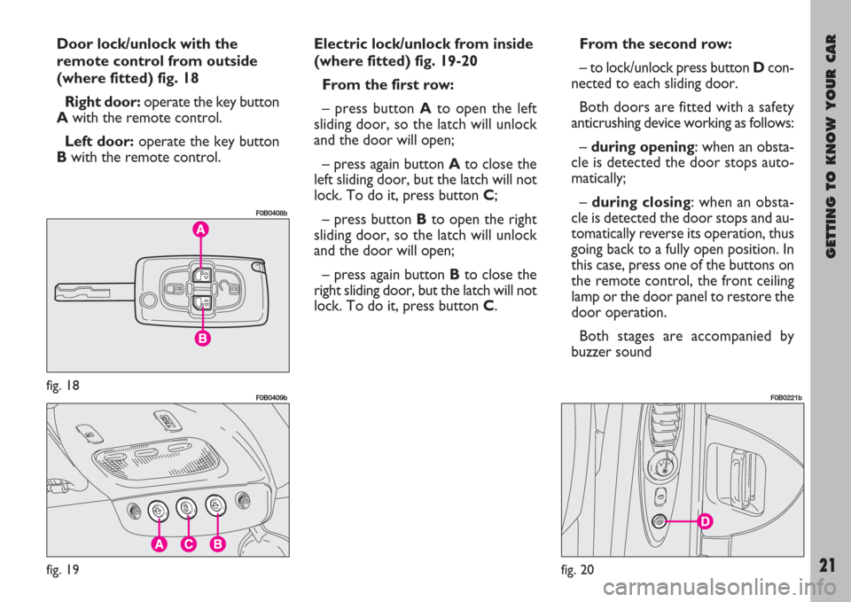
Door lock/unlock with the
remote control from outside
(where fitted) fig. 18
Right door:operate the key button
A with the remote control.
Left door:operate the key button
Bwith the remote control.Electric lock/unlock from inside
(where fitted) fig. 19-20
From the first row:
– press button A to open the left
sliding door, so the latch will unlock
and the door will open;
– press again button A to close the
left sliding door, but the latch will not
lock. To do it, press button C;
– press button Bto open the right
sliding door, so the latch will unlock
and the door will open;
– press again button Bto close the
right sliding door, but the latch will not
lock. To do it, press button C.From the second row:
– to lock/unlock press button Dcon-
nected to each sliding door.
Both doors are fitted with a safety
anticrushing device working as follows:
– during opening: when an obsta-
cle is detected the door stops auto-
matically;
– during closing: when an obsta-
cle is detected the door stops and au-
tomatically reverse its operation, thus
going back to a fully open position. In
this case, press one of the buttons on
the remote control, the front ceiling
lamp or the door panel to restore the
door operation.
Both stages are accompanied by
buzzer sound
fig. 18
F0B0408b
fig. 19
F0B0409b
fig. 20
F0B0221b
Page 23 of 254
GETTING TO KNOW YOUR CAR
22
CENTRAL DOOR LOCKING
SYSTEM
From the outside
With the doors closed: insert and
turn the key in the lock of one of the
front doors.
From the inside
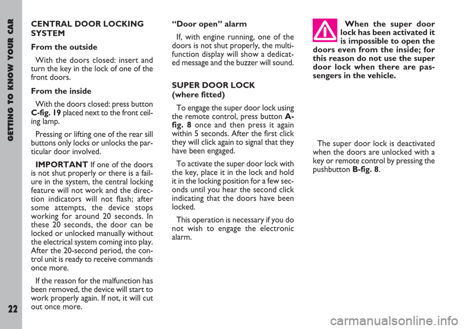
With the doors closed: press button
C-fig. 19placed next to the front ceil-
ing lamp.
Pressing or lifting one of the rear sill
buttons only locks or unlocks the par-
ticular door involved.
IMPORTANTIf one of the doors
is not shut properly or there is a fail-
ure in the system, the central locking
feature will not work and the direc-
tion indicators will not flash; after
some attempts, the device stops
working for around 20 seconds. In
these 20 seconds, the door can be
locked or unlocked manually without
the electrical system coming into play.
After the 20-second period, the con-
trol unit is ready to receive commands
once more.
If the reason for the malfunction has
been removed, the device will start to
work properly again. If not, it will cut
out once more.“Door open” alarm
If, with engine running, one of the
doors is not shut properly, the multi-
function display will show a dedicat-
ed message and the buzzer will sound.
SUPER DOOR LOCK
(where fitted)
To engage the super door lock using
the remote control, press button A-
fig. 8once and then press it again
within 5 seconds. After the first click
they will click again to signal that they
have been engaged.
To activate the super door lock with
the key, place it in the lock and hold
it in the locking position for a few sec-
onds until you hear the second click
indicating that the doors have been
locked.
This operation is necessary if you do
not wish to engage the electronic
alarm.When the super door
lock has been activated it
is impossible to open the
doors even from the inside; for
this reason do not use the super
door lock when there are pas-
sengers in the vehicle.
The super door lock is deactivated
when the doors are unlocked with a
key or remote control by pressing the
pushbutton B-fig. 8.
Page 26 of 254
GETTING TO KNOW YOUR CAR
25
ELECTRICALLY
ADJUSTABLE HEATED
FRONT SEATS
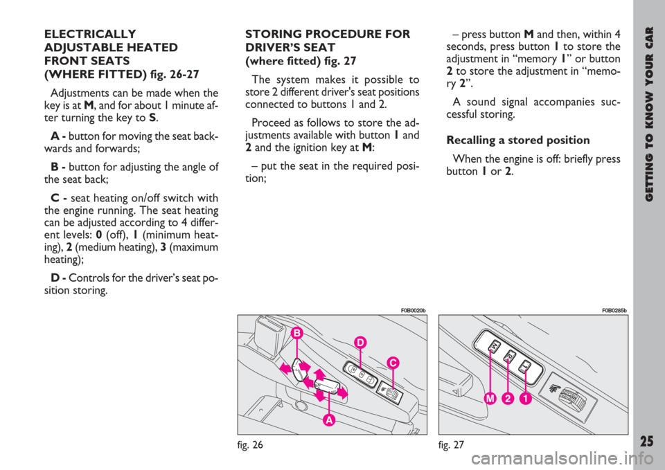
(WHERE FITTED) fig. 26-27
Adjustments can be made when the
key is at M, and for about 1 minute af-
ter turning the key to S.
A -button for moving the seat back-
wards and forwards;
B -button for adjusting the angle of
the seat back;
C -seat heating on/off switch with
the engine running. The seat heating
can be adjusted according to 4 differ-
ent levels: 0(off), 1(minimum heat-
ing), 2(medium heating), 3(maximum
heating);
D -Controls for the driver’s seat po-
sition storing. STORING PROCEDURE FOR
DRIVER’S SEAT
(where fitted) fig. 27
The system makes it possible to
store 2 different driver's seat positions
connected to buttons 1 and 2.
Proceed as follows to store the ad-
justments available with button 1and
2and the ignition key at M:
– put the seat in the required posi-
tion;– press button Mand then, within 4
seconds, press button 1to store the
adjustment in “memory 1” or button
2to store the adjustment in “memo-
ry 2”.
A sound signal accompanies suc-
cessful storing.
Recalling a stored position
When the engine is off: briefly press
button 1or 2.
fig. 26
F0B0020b
fig. 27
F0B0285b
Page 35 of 254
GETTING TO KNOW YOUR CAR
34
INDIVIDUAL
SETTINGS
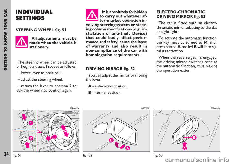
STEERING WHEEL fig. 51
DRIVING MIRROR fig. 52
You can adjust the mirror by moving
the lever:
A -anti-dazzle position;
B -normal position.ELECTRO-CHROMATIC
DRIVING MIRROR fig. 53
The car is fitted with an electro-
chromatic mirror adapting to the day
or night light.
To activate the automatic function,
the key must be turned to M, then
press button Aand led Bwill lit to sig-
nal its activation.
When the reverse gear is engaged,
the driving mirror switches over to
the automatic function, thus making
the operation easier.
fig. 51
F0B0037b
fig. 52
F0B0038b
fig. 53
F0B0039b
All adjustments must be
made when the vehicle is
stationary.
The steering wheel can be adjusted
for height and axis. Proceed as follows:
– lower lever to position 1.
– adjust the steering wheel.
– return the lever to position 2to
lock the wheel into position again.
It is absolutely forbidden
to carry out whatever af-
ter-market operation in-
volving steering system or steer-
ing column modifications (e.g.: in-
stallation of anti-theft Device)
that could badly affect perfor-
mance and safety, cause the lapse
of warranty and also result in
non-compliance of the car with
homologation requirements.
Page 36 of 254
GETTING TO KNOW YOUR CAR
35
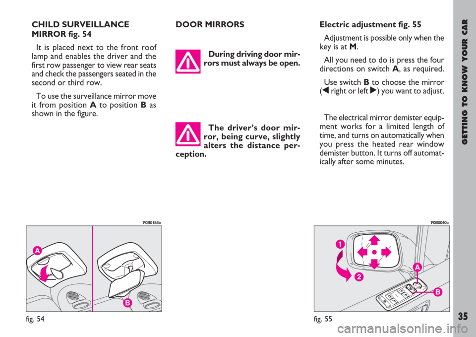
CHILD SURVEILLANCE
MIRROR fig. 54
It is placed next to the front roof
lamp and enables the driver and the
first row passenger to view rear seats
and check the passengers seated in the
second or third row.
To use the surveillance mirror move
it from position Ato position Bas
shown in the figure.DOOR MIRRORS
During driving door mir-
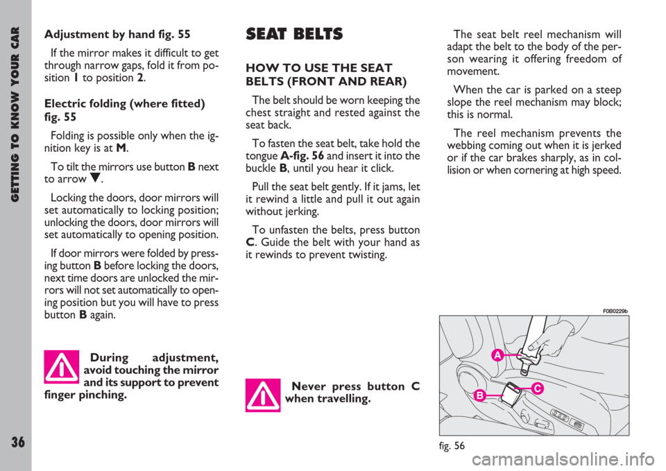
rors must always be open.Electric adjustment fig. 55
Adjustment is possible only when the
key is at M.
All you need to do is press the four
directions on switch A, as required.
Use switch Bto choose the mirror
(¯right or left ˙) you want to adjust.
The electrical mirror demister equip-
ment works for a limited length of
time, and turns on automatically when
you press the heated rear window
demister button. It turns off automat-
ically after some minutes.
fig. 54
F0B0185b
fig. 55
F0B0040b
The driver’s door mir-
ror, being curve, slightly
alters the distance per-
ception.
Page 37 of 254
GETTING TO KNOW YOUR CAR
36
Adjustment by hand fig. 55
If the mirror makes it difficult to get
through narrow gaps, fold it from po-
sition 1to position 2.
Electric folding (where fitted)
fig. 55
Folding is possible only when the ig-
nition key is at M.
To tilt the mirrors use button Bnext
to arrow O.
Locking the doors, door mirrors will
set automatically to locking position;
unlocking the doors, door mirrors will
set automatically to opening position.
If door mirrors were folded by press-
ing button Bbefore locking the doors,
next time doors are unlocked the mir-
rors will not set automatically to open-
ing position but you will have to press
button Bagain.SEAT BELTS
HOW TO USE THE SEAT
BELTS (FRONT AND REAR)
The belt should be worn keeping the
chest straight and rested against the
seat back.
To fasten the seat belt, take hold the
tongue A-fig. 56and insert it into the
buckle B, until you hear it click.
Pull the seat belt gently. If it jams, let
it rewind a little and pull it out again
without jerking.
To unfasten the belts, press button
C. Guide the belt with your hand as
it rewinds to prevent twisting.
Never press button C
when travelling.The seat belt reel mechanism will
adapt the belt to the body of the per-
son wearing it offering freedom of
movement.
When the car is parked on a steep
slope the reel mechanism may block;
this is normal.
The reel mechanism prevents the
webbing coming out when it is jerked
or if the car brakes sharply, as in col-
lision or when cornering at high speed.
fig. 56
F0B0229b
During adjustment,
avoid touching the mirror
and its support to prevent
finger pinching.
Page 55 of 254
GETTING TO KNOW YOUR CAR
54
ODOMETER DISPLAY
This instrument displays the follow-
ing values:
on the upper line:partial kilome-
tres and engine oil level gauge (where
fitted)
on the lower line:total kilometres
and programmed maintenance indica-
tor; versions with automatic gear are
also fitted with engaged gear indicator
(for further details see the chapter
“Automatic gear”).
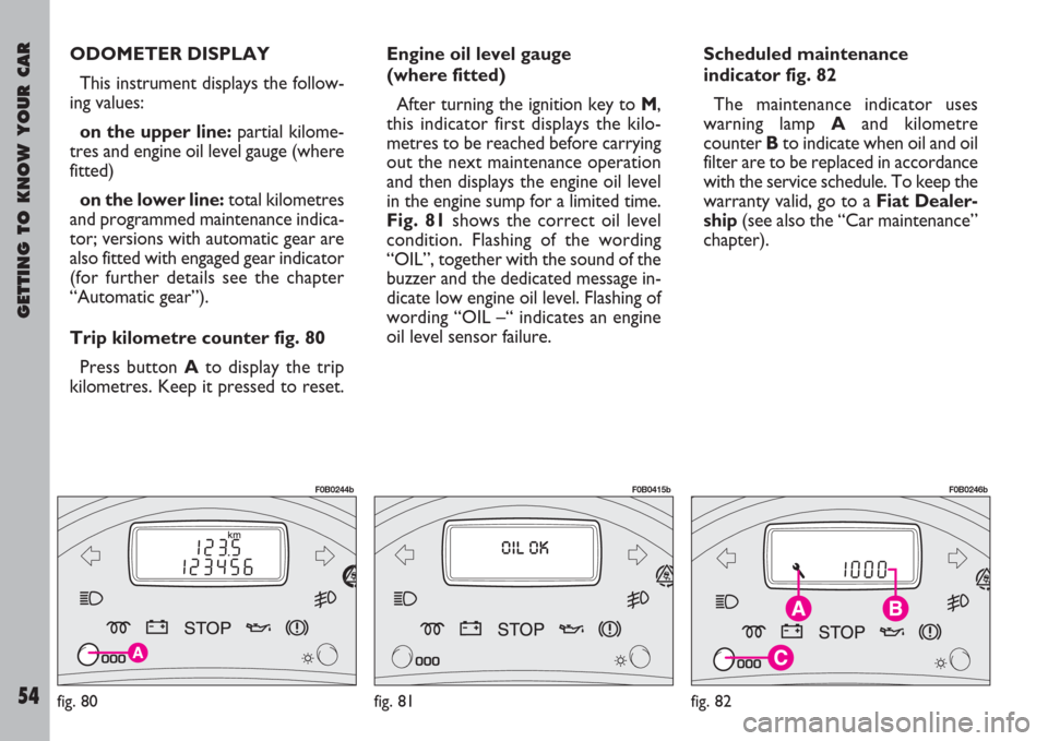
Trip kilometre counter fig. 80
Press button Ato display the trip
kilometres. Keep it pressed to reset.Engine oil level gauge
(where fitted)
After turning the ignition key to M,
this indicator first displays the kilo-
metres to be reached before carrying
out the next maintenance operation
and then displays the engine oil level
in the engine sump for a limited time.
Fig. 81shows the correct oil level
condition. Flashing of the wording
“OIL”, together with the sound of the
buzzer and the dedicated message in-
dicate low engine oil level. Flashing of
wording “OIL –“ indicates an engine
oil level sensor failure.
fig. 80
F0B0244b
fig. 81
F0B0415b
fig. 82
F0B0246b
Scheduled maintenance
indicator fig. 82
The maintenance indicator uses
warning lamp Aand kilometre
counter Bto indicate when oil and oil
filter are to be replaced in accordance
with the service schedule. To keep the
warranty valid, go to a Fiat Dealer-
ship(see also the “Car maintenance”
chapter).
Page 56 of 254
GETTING TO KNOW YOUR CAR
55
IMPORTANTAny anomalies
should be reported to your Fiat
Dealershipimmediately without
waiting for the next servicing coupon
to be carried out.
A- Maintenance warning lamp.
B- Kilometre counter.
C- Configuration and reset button.
O
PERATION
When the key is turned to M, warn-
ing lamp Awill light up for some sec-
onds and the kilometre counter Bwill
display the number of kilometres
(rounded down) still to be travelled
before the next servicing is due. Af-
ter this period the engine oil level
(where fitted) will be automatically dis-
played and then the total kilometres
travelled will be displayed as well;
– maintenance due after 2000
km until the maintenance dead-
line: when the key is turned to M,
warning lamp Awill light up and the
kilometre counter Bwill display the
number of kilometres (rounded
down) still to be travelled before the
next servicing is due. After some sec-
onds the warning lamp will remain litand the total travelled kilometres will
be displayed;
– maintenance overdue: when
the key is turned to M, warning lamp
Awill flash for some seconds and the
number of kilometres over the main-
tenance limit will be displayed; after
this period the warning lamp will re-
main lit and the total travelled kilo-
metres will be displayed.
IMPORTANTIf, after about
12 months, the kilometres indicated in
the Service Schedule have not been
reached yet, when the key is turned to
M, warning lamp Awill light up and
the kilometre counter will show 0 km.
In this case contact a Fiat Dealer-
ship.
C
ONFIGURATION PROCEDURE
If the vehicle is used in particularly
difficult conditions, you are recom-
mended to reset the system and re-
duce the maintenance frequency from
30,000 to 20,000 km.
To alter the maintenance frequency:
– turn the key to M;
– press button Cand keep it
pressed, so the number of kilometresstill remaining or already passed since
the scheduled servicing will flash;
– release the button immediately to
display the preset maintenance fre-
quency;
– a repeated press on button C will
change the maintenance frequency to
the one required:
30,000 km(recommended in nor-
mal use conditions);
20,000 km(recommended in se-
vere use conditions);
– when the selected maintenance fre-
quency is displayed, press button Cfor
10 seconds (the maintenance fre-
quency selected will flash for 10 sec-
onds);
– release the button to confirm as
soon as the display stops flashing.
Page 57 of 254
GETTING TO KNOW YOUR CAR
56
The navigation system
helps the driver while dri-
ving by suggesting, vocal-
ly and graphically, the best route
to be followed to reach the pre-
set destination. The suggestions
given by the navigation system do
not exempt the driver from fully
responsibility due to driving be-
haviour and compliance with
road and other traffic regulations.
The responsibility for road safety
always and anyway lies with the
vehicle’s driver.RESETTING
To reset the maintenance indicator:
– turn the ignition key to S;
– press and keep button Cpressed;
– turn the key to M;
– press and keep button Cpressed
for around 10 seconds so that the
maintenance indicator starts progres-
sive resetting until = 0 will be dis-
played;
– release button C and warning lamp
Awill go off to confirm successful re-
setting.
Your Fiat Dealership will reset
the maintenance indicator after
each control carried out.
INFOTELEMATIC
CONNECT SYSTEM
(where fitted)
The vehicle can be fitted with the in-
fotelematic CONNECT system which
includes a radio with CD-ROM/Audio
player, GSM cell phone, navigator and
on-board computer, designed in ac-
cordance with the specific features of
the passenger compartment and with
a personalised design that blends with
the styling of the dashboard.
The system is installed in an user-
friendly position for the driver and the
graphics on the front panel make it
easy to quickly locate the controls
which facilitate the use of them.
To use the system keep to the
instructions and warnings con-
cerning both its functions and the
relative road safety rules con-
tained in the specific Annex pro-
vided with the present Owner
Handbook.
Page 58 of 254
GETTING TO KNOW YOUR CAR
57
If the warning lamp
lights up while the vehicle
is moving, switch the en-
gine off and get in touch with a Fi-
at Dealership.
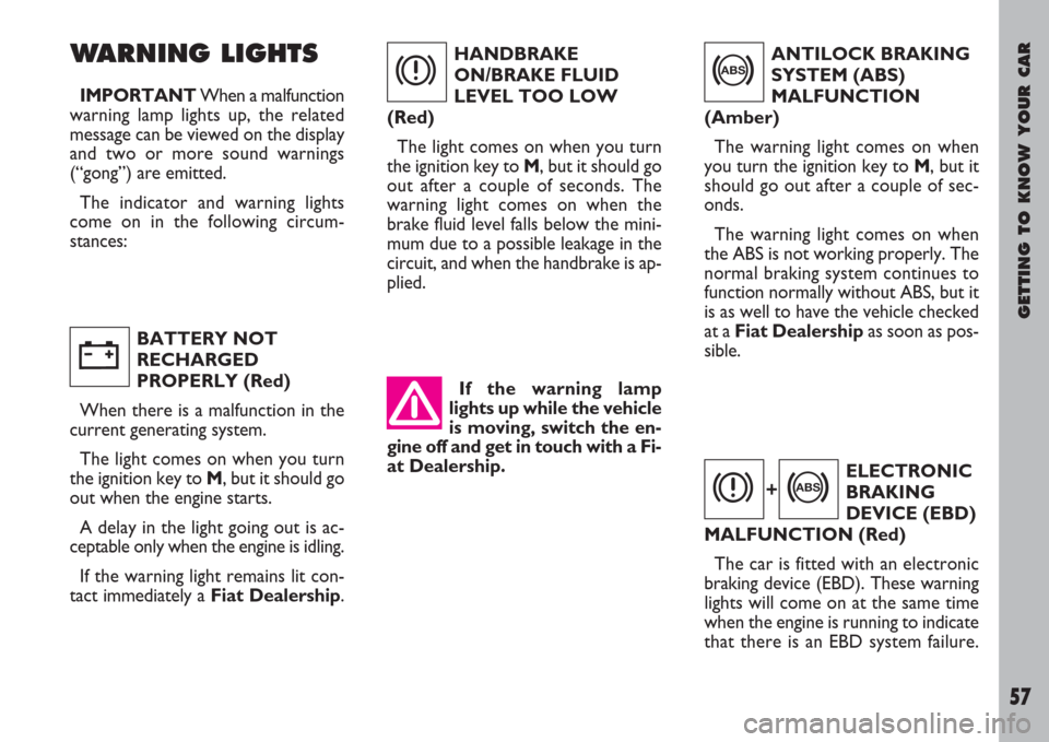
WARNING LIGHTS
IMPORTANTWhen a malfunction
warning lamp lights up, the related
message can be viewed on the display
and two or more sound warnings
(“gong”) are emitted.
The indicator and warning lights
come on in the following circum-
stances:
BATTERY NOT
RECHARGED
PROPERLY (Red)
When there is a malfunction in the
current generating system.
The light comes on when you turn
the ignition key to M, but it should go
out when the engine starts.
A delay in the light going out is ac-
ceptable only when the engine is idling.
If the warning light remains lit con-
tact immediately a Fiat Dealership.HANDBRAKE
ON/BRAKE FLUID
LEVEL TOO LOW
(Red)
The light comes on when you turn
the ignition key to M, but it should go
out after a couple of seconds. The
warning light comes on when the
brake fluid level falls below the mini-
mum due to a possible leakage in the
circuit, and when the handbrake is ap-
plied.
w
x
ANTILOCK BRAKING
SYSTEM (ABS)
MALFUNCTION
(Amber)
The warning light comes on when
you turn the ignition key to M, but it
should go out after a couple of sec-
onds.
The warning light comes on when
the ABS is not working properly. The
normal braking system continues to
function normally without ABS, but it
is as well to have the vehicle checked
at a Fiat Dealership as soon as pos-
sible.
>
ELECTRONIC
BRAKING
DEVICE (EBD)
MALFUNCTION (Red)
The car is fitted with an electronic
braking device (EBD). These warning
lights will come on at the same time
when the engine is running to indicate
that there is an EBD system failure.
x>+