ESP FIAT UNO 1983 Service User Guide
[x] Cancel search | Manufacturer: FIAT, Model Year: 1983, Model line: UNO, Model: FIAT UNO 1983Pages: 303, PDF Size: 10.36 MB
Page 54 of 303
towards the engine. Slip the belt off the
pulleys. If this is difficult, turn the crankshaft
pulley using a spanner on its retaining nut
while pressing the belt over the edge of the
pulley rim. Use this method to fit the new belt
after first having engaged it with the coolant
pump and alternator pulley grooves.
5Tension the belt as previously described.
6The tension of a new belt should be
checked and adjusted after the first few
hundred miles of running.
9 Coolant pump- removal,
overhaul and refitting
4
Note: The design of the pump differs between
the 903 cc and the other two engines, but the
removal, overhaul and refitting operations are
essentially similar.
1To gain access to the coolant pump, open
the bonnet and remove the air cleaner.
2Slacken the alternator pivot and adjustment
nuts, push the alternator in towards the
engine and slip the drivebelt from the coolant
pump pulley. Unplug and remove the
alternator.3Drain the cooling system as previously
described.
4Disconnect the hoses from the coolant
pump, also the metal coolant transfer pipe
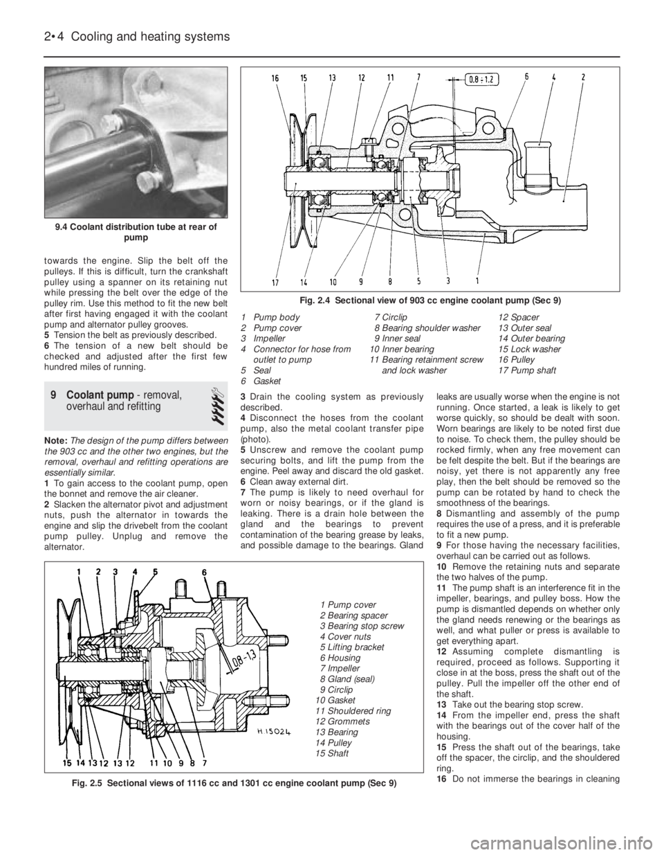
(photo).
5Unscrew and remove the coolant pump
securing bolts, and lift the pump from the
engine. Peel away and discard the old gasket.
6Clean away external dirt.
7The pump is likely to need overhaul for
worn or noisy bearings, or if the gland is
leaking. There is a drain hole between the
gland and the bearings to prevent
contamination of the bearing grease by leaks,
and possible damage to the bearings. Glandleaks are usually worse when the engine is not
running. Once started, a leak is likely to get
worse quickly, so should be dealt with soon.
Worn bearings are likely to be noted first due
to noise. To check them, the pulley should be
rocked firmly, when any free movement can
be felt despite the belt. But if the bearings are
noisy, yet there is not apparently any free
play, then the belt should be removed so the
pump can be rotated by hand to check the
smoothness of the bearings.
8Dismantling and assembly of the pump
requires the use of a press, and it is preferable
to fit a new pump.
9For those having the necessary facilities,
overhaul can be carried out as follows.
10Remove the retaining nuts and separate
the two halves of the pump.
11The pump shaft is an interference fit in the
impeller, bearings, and pulley boss. How the
pump is dismantled depends on whether only
the gland needs renewing or the bearings as
well, and what puller or press is available to
get everything apart.
12Assuming complete dismantling is
required, proceed as follows. Supporting it
close in at the boss, press the shaft out of the
pulley. Pull the impeller off the other end of
the shaft.
13Take out the bearing stop screw.
14From the impeller end, press the shaft
with the bearings out of the cover half of the
housing.
15Press the shaft out of the bearings, take
off the spacer, the circlip, and the shouldered
ring.
16Do not immerse the bearings in cleaning
2•4 Cooling and heating systems
1 Pump body
2 Pump cover
3 Impeller
4 Connector for hose from
outlet to pump
5 Seal
6 Gasket7 Circlip
8 Bearing shoulder washer
9 Inner seal
10 Inner bearing
11 Bearing retainment screw
and lock washer12 Spacer
13 Outer seal
14 Outer bearing
15 Lock washer
16 Pulley
17 Pump shaft
Fig. 2.5 Sectional views of 1116 cc and 1301 cc engine coolant pump (Sec 9)
Fig. 2.4 Sectional view of 903 cc engine coolant pump (Sec 9)
9.4 Coolant distribution tube at rear of
pump
1 Pump cover
2 Bearing spacer
3 Bearing stop screw
4 Cover nuts
5 Lifting bracket
6 Housing
7 Impeller
8 Gland (seal)
9 Circlip
10 Gasket
11 Shouldered ring
12 Grommets
13 Bearing
14 Pulley
15 Shaft
Page 63 of 303
12The air cleaner on the 1301 cc engine is
mounted on the four flange studs of the
carburettors, their nuts being accessible after
the air cleaner lid has been removed and the
filter element extracted.
13Refitting of all types of air cleaner is a
reversal of removal.
3 Fuel pump-
removal and refitting
2
1On 903 cc engines, the fuel pump is
mounted on the side of the timing chain cover
and is driven by a pushrod from an eccentric
on the front of the camshaft.
2On the 1116 cc and 1301 cc engines, the
fuel pump is mounted on the side of the
crankcase and is driven by a pushrod from an
eccentric on the auxiliary shaft.
3The removal of both types of pump is
carried out in a similar way.
4Disconnect the fuel inlet hose from the
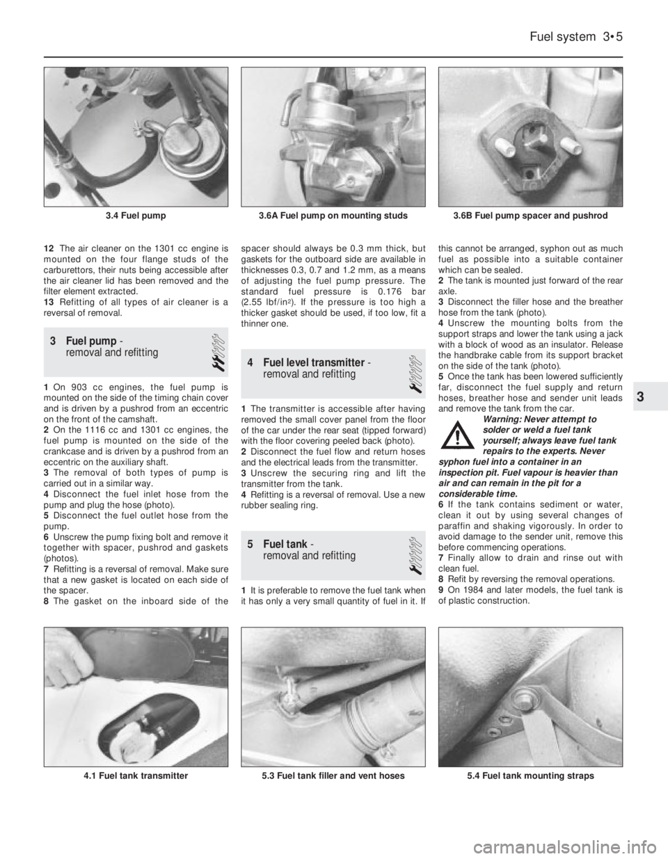
pump and plug the hose (photo).
5Disconnect the fuel outlet hose from the
pump.
6Unscrew the pump fixing bolt and remove it
together with spacer, pushrod and gaskets
(photos).
7Refitting is a reversal of removal. Make sure
that a new gasket is located on each side of
the spacer.
8The gasket on the inboard side of thespacer should always be 0.3 mm thick, but
gaskets for the outboard side are available in
thicknesses 0.3, 0.7 and 1.2 mm, as a means
of adjusting the fuel pump pressure. The
standard fuel pressure is 0.176 bar
(2.55 lbf/in
2). If the pressure is too high a
thicker gasket should be used, if too low, fit a
thinner one.
4 Fuel level transmitter-
removal and refitting
1
1The transmitter is accessible after having
removed the small cover panel from the floor
of the car under the rear seat (tipped forward)
with the floor covering peeled back (photo).
2Disconnect the fuel flow and return hoses
and the electrical leads from the transmitter.
3Unscrew the securing ring and lift the
transmitter from the tank.
4Refitting is a reversal of removal. Use a new
rubber sealing ring.
5 Fuel tank-
removal and refitting
1
1It is preferable to remove the fuel tank when
it has only a very small quantity of fuel in it. Ifthis cannot be arranged, syphon out as much
fuel as possible into a suitable container
which can be sealed.
2The tank is mounted just forward of the rear
axle.
3Disconnect the filler hose and the breather
hose from the tank (photo).
4Unscrew the mounting bolts from the
support straps and lower the tank using a jack
with a block of wood as an insulator. Release
the handbrake cable from its support bracket
on the side of the tank (photo).
5Once the tank has been lowered sufficiently
far, disconnect the fuel supply and return
hoses, breather hose and sender unit leads
and remove the tank from the car.
Warning: Never attempt to
solder or weld a fuel tank
yourself; always leave fuel tank
repairs to the experts. Never
syphon fuel into a container in an
inspection pit. Fuel vapour is heavier than
air and can remain in the pit for a
considerable time.
6If the tank contains sediment or water,
clean it out by using several changes of
paraffin and shaking vigorously. In order to
avoid damage to the sender unit, remove this
before commencing operations.
7Finally allow to drain and rinse out with
clean fuel.
8Refit by reversing the removal operations.
9On 1984 and later models, the fuel tank is
of plastic construction.
Fuel system 3•5
3.6B Fuel pump spacer and pushrod3.6A Fuel pump on mounting studs3.4 Fuel pump
5.4 Fuel tank mounting straps5.3 Fuel tank filler and vent hoses4.1 Fuel tank transmitter
3
Page 71 of 303
6On 1116 cc and 1301 cc models, the
exhaust system is of dual downpipe, two
silencer, two section type.
7The exhaust system is flexibly mounted
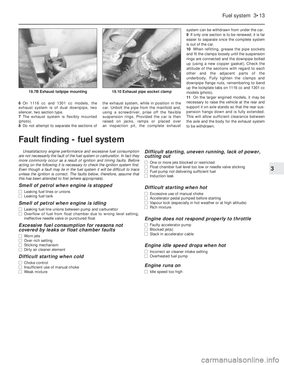
(photo).
8Do not attempt to separate the sections ofthe exhaust system, while in position in the
car. Unbolt the pipe from the manifold and,
using a screwdriver, prise off the flexible
suspension rings. Provided the car is then
raised on jacks, ramps or placed over
an inspection pit, the complete exhaust system can be withdrawn from under the car.
9If only one section is to be renewed, it is far
easier to separate once the complete system
is out of the car.
10When refitting, grease the pipe sockets
and fit the clamps loosely until the suspension
rings are connected and the downpipe bolted
up (using a new copper gasket). Check the
attitude of the sections with regard to each
other and the adjacent parts of the
underbody. Fully tighten the clamps and
downpipe flange nuts, remembering to bend
up the lockplate tabs on 1116 cc and 1301 cc
models (photo).
11On the larger engined models, it may be
necessary to raise the vehicle at the rear and
support it on axle stands so that the rear sus-
pension hangs down and is fully extended.
This will allow sufficient clearance between
the axle and the body for the exhaust system
to be withdrawn.
Fuel system 3•13
3
19.10 Exhaust pipe socket clamp19.7B Exhaust tailpipe mounting
Fault finding - fuel system
Unsatisfactory engine performance and excessive fuel consumption
are not necessarily the fault of the fuel system or carburettor. In fact they
more commonly occur as a result of ignition and timing faults. Before
acting on the following it is necessary to check the ignition system first.
Even though a fault may lie in the fuel system it will be difficult to trace
unless the ignition is correct. The faults below, therefore, assume that
this has been attended to first (where appropriate).
Smell of petrol when engine is stopped
m mLeaking fuel lines or unions
m mLeaking fuel tank
Smell of petrol when engine is idling
m
mLeaking fuel line unions between pump and carburettor
m mOverflow of fuel from float chamber due to wrong level setting,
ineffective needle valve or punctured float
Excessive fuel consumption for reasons not
covered by leaks or float chamber faults
m mWorn jets
m mOver-rich setting
m mSticking mechanism
m mDirty air cleaner element
Difficult starting when cold
m
mChoke control
m mInsufficient use of manual choke
m mWeak mixture
Difficult starting, uneven running, lack of power,
cutting out
m mOne or more jets blocked or restricted
m mFloat chamber fuel level too low or needle valve sticking
m mFuel pump not delivering sufficient fuel
m mInduction leak
Difficult starting when hot
m
mExcessive use of manual choke
m mAccelerator pedal pumped before starting
m mVapour lock (especially in hot weather or at high altitude)
m mRich mixture
Engine does not respond properly to throttle
m
mFaulty accelerator pump
m mBlocked jet(s)
m mSlack in accelerator cable
Engine idle speed drops when hot
m
mIncorrect air cleaner intake setting
m mOverheated fuel pump
Engine runs on
m
mIdle speed too high
Page 74 of 303
outwards, they rotate the cam relative to the
distributor shaft, and so advance the spark.
The weights are held in position by two
springs and it is the tension of the springs
which is largely responsible for correct spark
advancement.
The vacuum advance is controlled by a
diaphragm capsule connected to the
carburettor venturi. The vacuum pressure
varies according to the throttle valve plate
opening and so adjusts the ignition advance
in accordance with the engine requirements.
Digiplex ignition system
This electronic system eliminates the
mechanical contact breaker and centrifugal
advance mechanism of conventional
distributors and uses an electronic control
unit to provide advance values according to
engine speed and load. No provision is made
for adjustment of the ignition timing.
Information relayed to the control unit is
provided by two magnetic sensors which
monitor engine speed and TDC directly from
the engine crankshaft.
A vacuum sensor in the control unit
converts intake manifold vacuum into an
electric signal.
The control unit selects the optimum
advance angle required and a closed
magnetic circuit resin coil guarantees a spark
owing to the low primary winding resistance.
Five hundred and twelve advance values
are stored in the control unit memory to suit
any combination of engine operating
conditions.
No maintenance is required to the
distributor used on this system.
Distributor drive
The mechanical breaker type distributor on
903 cc engines and the Digiplex type
distributor on 903 cc ES engines are mounted
on the cylinder head and driven from a gear
on the camshaft through a shaft which also
drives the oil pump.
The distributor on 1116 cc and 1301 cc
engines is mounted on the crankcase and is
driven from a gear on the auxiliary shaft as is
also the oil pump.
2 Mechanical contact breaker
- points servicing
3
1At the intervals specified in “Routine
Maintenance”, prise down the clips on the
distributor cap and place the cap with high
tension leads to one side.
2Pull off the rotor.
3Remove the spark shield. Mechanical wear
of the contact breaker reduces the gap.
Electrical wear builds up a “pip” of burned
metal on one of the contacts. This
|prevents the gap being measured for
re-adjustment, and also spoils the electric
circuit.
Ducellier type distributor
4To remove the contact breaker movable
arm, extract the clip and take off the washer
from the top of the pivot post.
5Extract the screw and remove the fixed
contact arm.
6Clean the points by rubbing the surfaces on
a fine abrasive such as an oil stone. The point
surface should be shaped to a gentle convex
curve. All the “pip” burned onto one contact
must be removed. It is not necessary to go on
until all traces of the crater have been
removed from the other. There is enough
metal on the contacts to allow this to be done
once. At alternate services, fit new points.
Wash debris off cleaned points and
preservatives off new ones.
7Now the distributor should be lubricated.
This lubrication is important for the correct
mechanical function of the distributor, but
excess lubrication will ruin the electrical
circuits, and give difficult starting.
8Whilst the contact breaker is off, squirt
some engine oil into the bottom part of the
distributor, onto the centrifugal advance
mechanism below the plate.
9Wet with oil the felt pad on the top of the
distributor spindle, normally covered by the
rotor arm.
10Put just a drip of oil on the pivot for the
moving contact.11Smear a little general purpose grease
onto the cam, and the heel of the moving
contact breaker.
12Refit the contact points and then set the
gap in the following way.
13Turn the crankshaft by applying a spanner
to the pulley nut or by jacking up a front
wheel, engaging top gear and turning the
roadwheel in the forward direction of
travel. Keep turning until the plastic
heel of the movable contact arm is on the
high point of a cam lobe on the distributor
shaft.
14Set the points gap by moving the fixed
contact arm until the specified feeler blades
are a sliding fit. Tighten the fixed contact arm
screw.
15Check the contact end of the rotor arm.
Remove any slightly burnt deposits using fine
abrasive paper. Severe erosion will
necessitate renewal of the rotor.
16Wipe out the distributor cap and check for
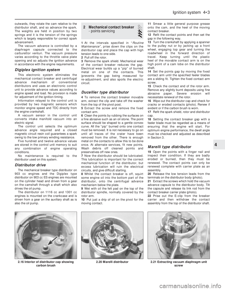
cracks or eroded contacts (photo). Renew if
evident or if the carbon brush is worn.
17Refit the spark shield, rotor and distributor
cap.
18Setting the contact breaker gap with a
feeler blade must be regarded as a means of
ensuring that the engine will start. For
optimum engine performance, the dwell angle
must be checked and adjusted as described
in Section 3.
Marelli type distributor
19Open the points with a finger nail and
inspect their condition. If they are badly
eroded or burned, then they must be
renewed. The contact points can only be
renewed complete with carrier plate as an
assembly.
20Release the low tension leads from the
terminals on the distributor body (photo).
21Extract the screws which hold the vacuum
advance capsule to the distributor body. Tilt
the capsule and release its link rod from the
contact breaker carrier plate (photo).
22Prise out the E-clip from the breaker
carrier and then withdraw the contact
assembly from the top of the distributor shaft.
Ignition system 4•3
2.21 Extracting vacuum diaphragm unit
screw2.20 Marelli distributor2.16 Interior of distributor cap showing
carbon brush
4
Page 79 of 303
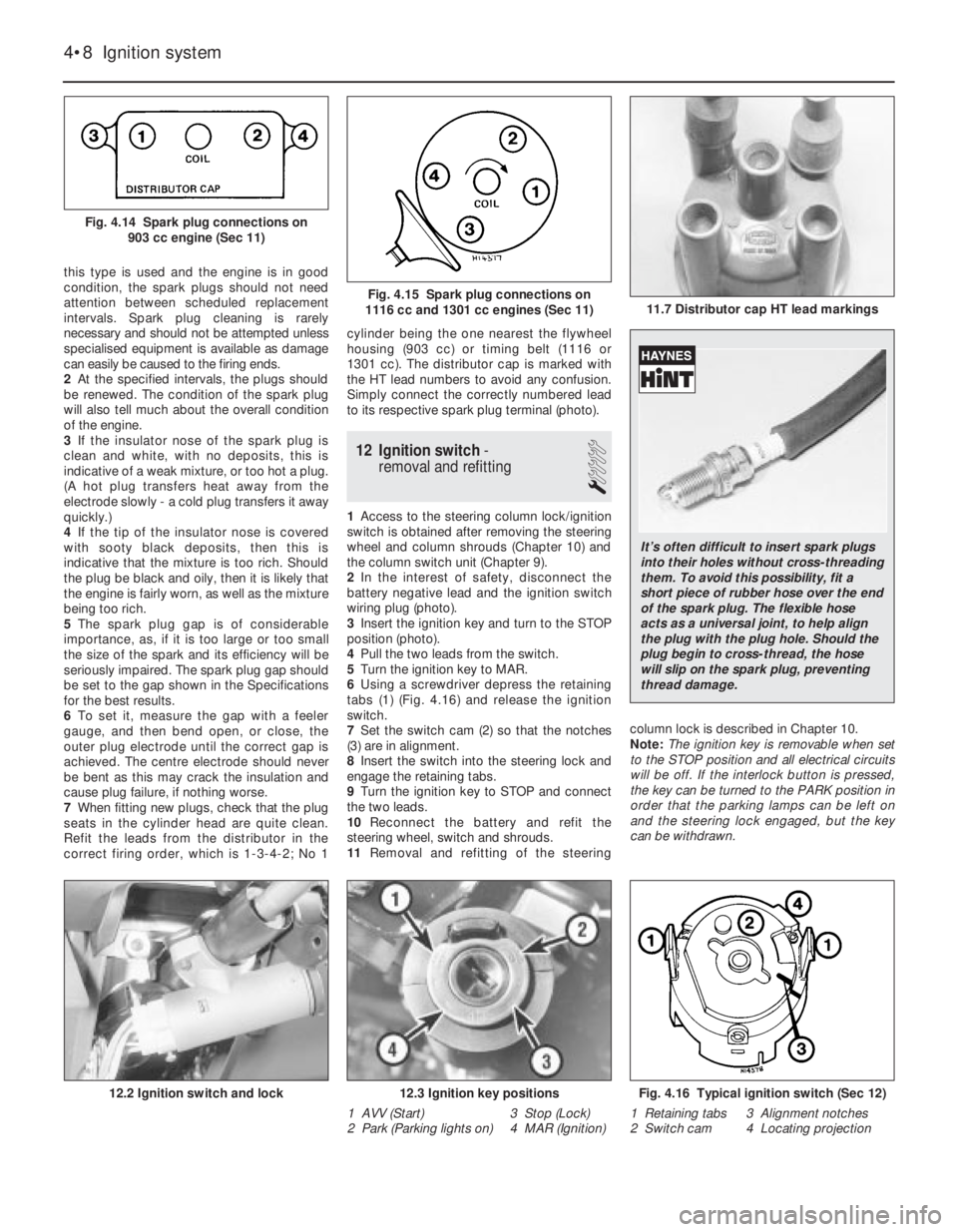
this type is used and the engine is in good
condition, the spark plugs should not need
attention between scheduled replacement
intervals. Spark plug cleaning is rarely
necessary and should not be attempted unless
specialised equipment is available as damage
can easily be caused to the firing ends.
2At the specified intervals, the plugs should
be renewed. The condition of the spark plug
will also tell much about the overall condition
of the engine.
3If the insulator nose of the spark plug is
clean and white, with no deposits, this is
indicative of a weak mixture, or too hot a plug.
(A hot plug transfers heat away from the
electrode slowly - a cold plug transfers it away
quickly.)
4If the tip of the insulator nose is covered
with sooty black deposits, then this is
indicative that the mixture is too rich. Should
the plug be black and oily, then it is likely that
the engine is fairly worn, as well as the mixture
being too rich.
5The spark plug gap is of considerable
importance, as, if it is too large or too small
the size of the spark and its efficiency will be
seriously impaired. The spark plug gap should
be set to the gap shown in the Specifications
for the best results.
6To set it, measure the gap with a feeler
gauge, and then bend open, or close, the
outer plug electrode until the correct gap is
achieved. The centre electrode should never
be bent as this may crack the insulation and
cause plug failure, if nothing worse.
7When fitting new plugs, check that the plug
seats in the cylinder head are quite clean.
Refit the leads from the distributor in the
correct firing order, which is 1-3-4-2; No 1cylinder being the one nearest the flywheel
housing (903 cc) or timing belt (1116 or
1301 cc). The distributor cap is marked with
the HT lead numbers to avoid any confusion.
Simply connect the correctly numbered lead
to its respective spark plug terminal (photo).
12 Ignition switch-
removal and refitting
1
1Access to the steering column lock/ignition
switch is obtained after removing the steering
wheel and column shrouds (Chapter 10) and
the column switch unit (Chapter 9).
2In the interest of safety, disconnect the
battery negative lead and the ignition switch
wiring plug (photo).
3Insert the ignition key and turn to the STOP
position (photo).
4Pull the two leads from the switch.
5Turn the ignition key to MAR.
6Using a screwdriver depress the retaining
tabs (1) (Fig. 4.16) and release the ignition
switch.
7Set the switch cam (2) so that the notches
(3) are in alignment.
8Insert the switch into the steering lock and
engage the retaining tabs.
9Turn the ignition key to STOP and connect
the two leads.
10Reconnect the battery and refit the
steering wheel, switch and shrouds.
11Removal and refitting of the steeringcolumn lock is described in Chapter 10.
Note: The ignition key is removable when set
to the STOP position and all electrical circuits
will be off. If the interlock button is pressed,
the key can be turned to the PARK position in
order that the parking lamps can be left on
and the steering lock engaged, but the key
can be withdrawn.
4•8 Ignition system
Fig. 4.16 Typical ignition switch (Sec 12)
1 Retaining tabs 3 Alignment notches
2 Switch cam 4 Locating projection12.3 Ignition key positions
1 AVV (Start) 3 Stop (Lock)
2 Park (Parking lights on) 4 MAR (Ignition)12.2 Ignition switch and lock
11.7 Distributor cap HT lead markingsFig. 4.15 Spark plug connections on
1116 cc and 1301 cc engines (Sec 11)
Fig. 4.14 Spark plug connections on
903 cc engine (Sec 11)
It’s often difficult to insert spark plugs
into their holes without cross-threading
them. To avoid this possibility, fit a
short piece of rubber hose over the end
of the spark plug. The flexible hose
acts as a universal joint, to help align
the plug with the plug hole. Should the
plug begin to cross-thread, the hose
will slip on the spark plug, preventing
thread damage.
Page 83 of 303
into its cylinder to accommodate them. This
will cause the fluid level to rise in the reservoir.
Anticipate this by syphoning some out
beforehand, but take care not to let it drip
onto the paintwork - it acts as an effective
paint stripperl
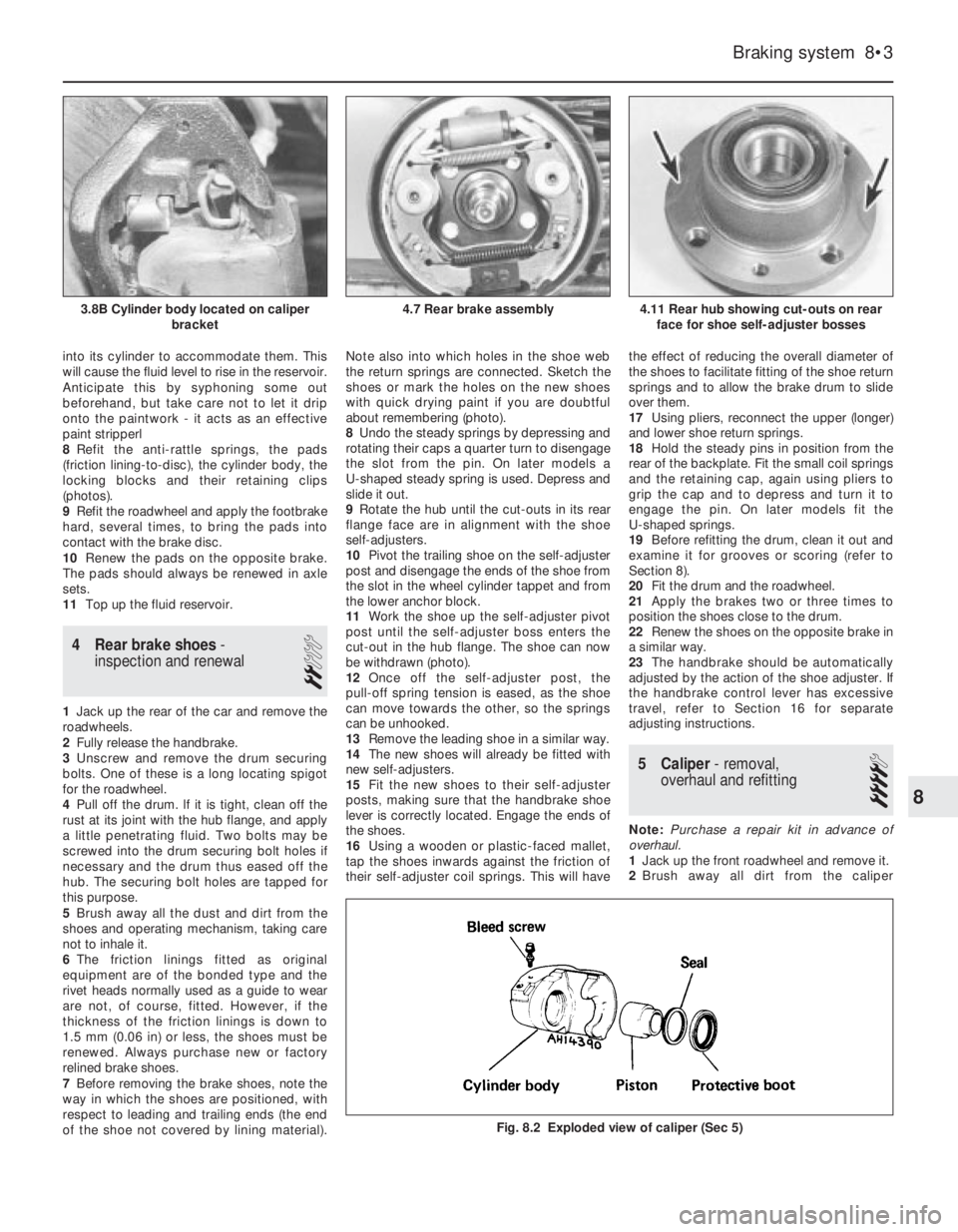
8Refit the anti-rattle springs, the pads
(friction lining-to-disc), the cylinder body, the
locking blocks and their retaining clips
(photos).
9Refit the roadwheel and apply the footbrake
hard, several times, to bring the pads into
contact with the brake disc.
10Renew the pads on the opposite brake.
The pads should always be renewed in axle
sets.
11Top up the fluid reservoir.
4 Rear brake shoes-
inspection and renewal
2
1Jack up the rear of the car and remove the
roadwheels.
2Fully release the handbrake.
3Unscrew and remove the drum securing
bolts. One of these is a long locating spigot
for the roadwheel.
4Pull off the drum. lf it is tight, clean off the
rust at its joint with the hub flange, and apply
a little penetrating fluid. Two bolts may be
screwed into the drum securing bolt holes if
necessary and the drum thus eased off the
hub. The securing bolt holes are tapped for
this purpose.
5Brush away all the dust and dirt from the
shoes and operating mechanism, taking care
not to inhale it.
6The friction linings fitted as original
equipment are of the bonded type and the
rivet heads normally used as a guide to wear
are not, of course, fitted. However, if the
thickness of the friction linings is down to
1.5 mm (0.06 in) or less, the shoes must be
renewed. Always purchase new or factory
relined brake shoes.
7Before removing the brake shoes, note the
way in which the shoes are positioned, with
respect to leading and trailing ends (the end
of the shoe not covered by lining material).Note also into which holes in the shoe web
the return springs are connected. Sketch the
shoes or mark the holes on the new shoes
with quick drying paint if you are doubtful
about remembering (photo).
8Undo the steady springs by depressing and
rotating their caps a quarter turn to disengage
the slot from the pin. On later models a
U-shaped steady spring is used. Depress and
slide it out.
9Rotate the hub until the cut-outs in its rear
flange face are in alignment with the shoe
self-adjusters.
10Pivot the trailing shoe on the self-adjuster
post and disengage the ends of the shoe from
the slot in the wheel cylinder tappet and from
the lower anchor block.
11Work the shoe up the self-adjuster pivot
post until the self-adjuster boss enters the
cut-out in the hub flange. The shoe can now
be withdrawn (photo).
12Once off the self-adjuster post, the
pull-off spring tension is eased, as the shoe
can move towards the other, so the springs
can be unhooked.
13Remove the leading shoe in a similar way.
14The new shoes will already be fitted with
new self-adjusters.
15Fit the new shoes to their self-adjuster
posts, making sure that the handbrake shoe
lever is correctly located. Engage the ends of
the shoes.
16Using a wooden or plastic-faced mallet,
tap the shoes inwards against the friction of
their self-adjuster coil springs. This will havethe effect of reducing the overall diameter of
the shoes to facilitate fitting of the shoe return
springs and to allow the brake drum to slide
over them.
17Using pliers, reconnect the upper (longer)
and lower shoe return springs.
18Hold the steady pins in position from the
rear of the backplate. Fit the small coil springs
and the retaining cap, again using pliers to
grip the cap and to depress and turn it to
engage the pin. On later models fit the
U-shaped springs.
19Before refitting the drum, clean it out and
examine it for grooves or scoring (refer to
Section 8).
20Fit the drum and the roadwheel.
21Apply the brakes two or three times to
position the shoes close to the drum.
22Renew the shoes on the opposite brake in
a similar way.
23The handbrake should be automatically
adjusted by the action of the shoe adjuster. If
the handbrake control lever has excessive
travel, refer to Section 16 for separate
adjusting instructions.
5 Caliper- removal,
overhaul and refitting
4
Note: Purchase a repair kit in advance of
overhaul.
1Jack up the front roadwheel and remove it.
2Brush away all dirt from the caliper
Braking system 8•3
4.11 Rear hub showing cut-outs on rear
face for shoe self-adjuster bosses4.7 Rear brake assembly3.8B Cylinder body located on caliper
bracket
Fig. 8.2 Exploded view of caliper (Sec 5)
8
Page 96 of 303
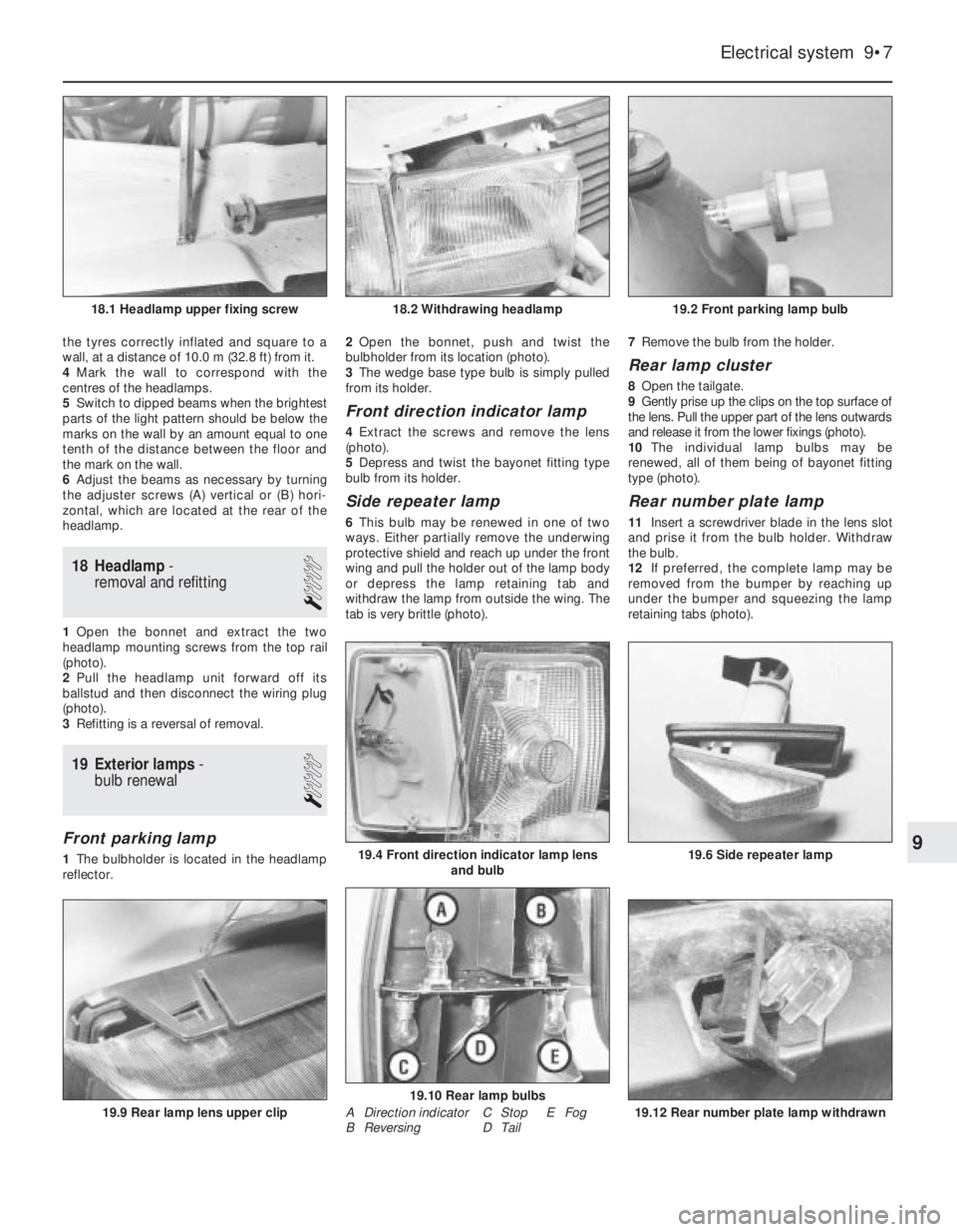
the tyres correctly inflated and square to a
wall, at a distance of 10.0 m (32.8 ft) from it.
4Mark the wall to correspond with the
centres of the headlamps.
5Switch to dipped beams when the brightest
parts of the light pattern should be below the
marks on the wall by an amount equal to one
tenth of the distance between the floor and
the mark on the wall.
6Adjust the beams as necessary by turning
the adjuster screws (A) vertical or (B) hori-
zontal, which are located at the rear of the
headlamp.
18 Headlamp-
removal and refitting
1
1Open the bonnet and extract the two
headlamp mounting screws from the top rail
(photo).
2Pull the headlamp unit forward off its
ballstud and then disconnect the wiring plug
(photo).
3Refitting is a reversal of removal.
19 Exterior lamps-
bulb renewal
1
Front parking lamp
1The bulbholder is located in the headlamp
reflector. 2Open the bonnet, push and twist the
bulbholder from its location (photo).
3The wedge base type bulb is simply pulled
from its holder.
Front direction indicator lamp
4Extract the screws and remove the lens
(photo).
5Depress and twist the bayonet fitting type
bulb from its holder.
Side repeater lamp
6This bulb may be renewed in one of two
ways. Either partially remove the underwing
protective shield and reach up under the front
wing and pull the holder out of the lamp body
or depress the lamp retaining tab and
withdraw the lamp from outside the wing. The
tab is very brittle (photo). 7Remove the bulb from the holder.
Rear lamp cluster
8Open the tailgate.
9Gently prise up the clips on the top surface of
the lens. Pull the upper part of the lens outwards
and release it from the lower fixings (photo).
10The individual lamp bulbs may be
renewed, all of them being of bayonet fitting
type (photo).
Rear number plate lamp
11Insert a screwdriver blade in the lens slot
and prise it from the bulb holder. Withdraw
the bulb.
12If preferred, the complete lamp may be
removed from the bumper by reaching up
under the bumper and squeezing the lamp
retaining tabs (photo).
Electrical system 9•7
19.2 Front parking lamp bulb18.2 Withdrawing headlamp18.1 Headlamp upper fixing screw
19.12 Rear number plate lamp withdrawn
19.10 Rear lamp bulbs
19.6 Side repeater lamp19.4 Front direction indicator lamp lens
and bulb
19.9 Rear lamp lens upper clip
9
A Direction indicator
B ReversingC Stop E Fog
D Tail
Page 99 of 303
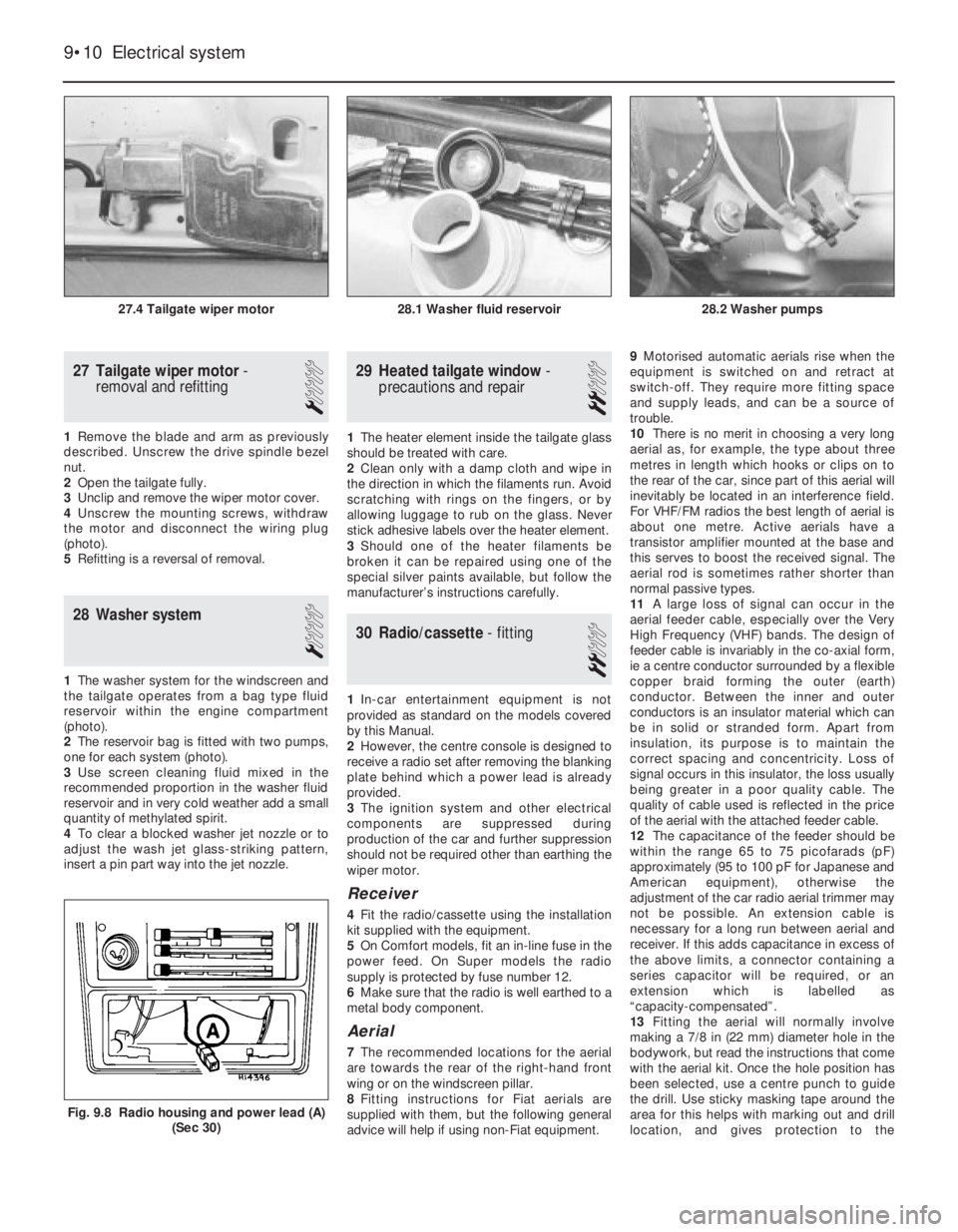
27 Tailgate wiper motor-
removal and refitting
1
1Remove the blade and arm as previously
described. Unscrew the drive spindle bezel
nut.
2Open the tailgate fully.
3Unclip and remove the wiper motor cover.
4Unscrew the mounting screws, withdraw
the motor and disconnect the wiring plug
(photo).
5Refitting is a reversal of removal.
28 Washer system
1
1The washer system for the windscreen and
the tailgate operates from a bag type fluid
reservoir within the engine compartment
(photo).
2The reservoir bag is fitted with two pumps,
one for each system (photo).
3Use screen cleaning fluid mixed in the
recommended proportion in the washer fluid
reservoir and in very cold weather add a small
quantity of methylated spirit.
4To clear a blocked washer jet nozzle or to
adjust the wash jet glass-striking pattern,
insert a pin part way into the jet nozzle.
29 Heated tailgate window-
precautions and repair
2
1The heater element inside the tailgate glass
should be treated with care.
2Clean only with a damp cloth and wipe in
the direction in which the filaments run. Avoid
scratching with rings on the fingers, or by
allowing luggage to rub on the glass. Never
stick adhesive labels over the heater element.
3Should one of the heater filaments be
broken it can be repaired using one of the
special silver paints available, but follow the
manufacturer’s instructions carefully.
30 Radio/cassette- fitting
2
1In-car entertainment equipment is not
provided as standard on the models covered
by this Manual.
2However, the centre console is designed to
receive a radio set after removing the blanking
plate behind which a power lead is already
provided.
3The ignition system and other electrical
components are suppressed during
production of the car and further suppression
should not be required other than earthing the
wiper motor.
Receiver
4Fit the radio/cassette using the installation
kit supplied with the equipment.
5On Comfort models, fit an in-line fuse in the
power feed. On Super models the radio
supply is protected by fuse number 12.
6Make sure that the radio is well earthed to a
metal body component.
Aerial
7The recommended locations for the aerial
are towards the rear of the right-hand front
wing or on the windscreen pillar.
8Fitting instructions for Fiat aerials are
supplied with them, but the following general
advice will help if using non-Fiat equipment.9Motorised automatic aerials rise when the
equipment is switched on and retract at
switch-off. They require more fitting space
and supply leads, and can be a source of
trouble.
10There is no merit in choosing a very long
aerial as, for example, the type about three
metres in length which hooks or clips on to
the rear of the car, since part of this aerial will
inevitably be located in an interference field.
For VHF/FM radios the best length of aerial is
about one metre. Active aerials have a
transistor amplifier mounted at the base and
this serves to boost the received signal. The
aerial rod is sometimes rather shorter than
normal passive types.
11A large loss of signal can occur in the
aerial feeder cable, especially over the Very
High Frequency (VHF) bands. The design of
feeder cable is invariably in the co-axial form,
ie a centre conductor surrounded by a flexible
copper braid forming the outer (earth)
conductor. Between the inner and outer
conductors is an insulator material which can
be in solid or stranded form. Apart from
insulation, its purpose is to maintain the
correct spacing and concentricity. Loss of
signal occurs in this insulator, the loss usually
being greater in a poor quality cable. The
quality of cable used is reflected in the price
of the aerial with the attached feeder cable.
12The capacitance of the feeder should be
within the range 65 to 75 picofarads (pF)
approximately (95 to 100 pF for Japanese and
American equipment), otherwise the
adjustment of the car radio aerial trimmer may
not be possible. An extension cable is
necessary for a long run between aerial and
receiver. If this adds capacitance in excess of
the above limits, a connector containing a
series capacitor will be required, or an
extension which is labelled as
“capacity-compensated”.
13Fitting the aerial will normally involve
making a 7/8 in (22 mm) diameter hole in the
bodywork, but read the instructions that come
with the aerial kit. Once the hole position has
been selected, use a centre punch to guide
the drill. Use sticky masking tape around the
area for this helps with marking out and drill
location, and gives protection to the
9•10 Electrical system
Fig. 9.8 Radio housing and power lead (A)
(Sec 30)
28.2 Washer pumps28.1 Washer fluid reservoir27.4 Tailgate wiper motor
Page 103 of 303
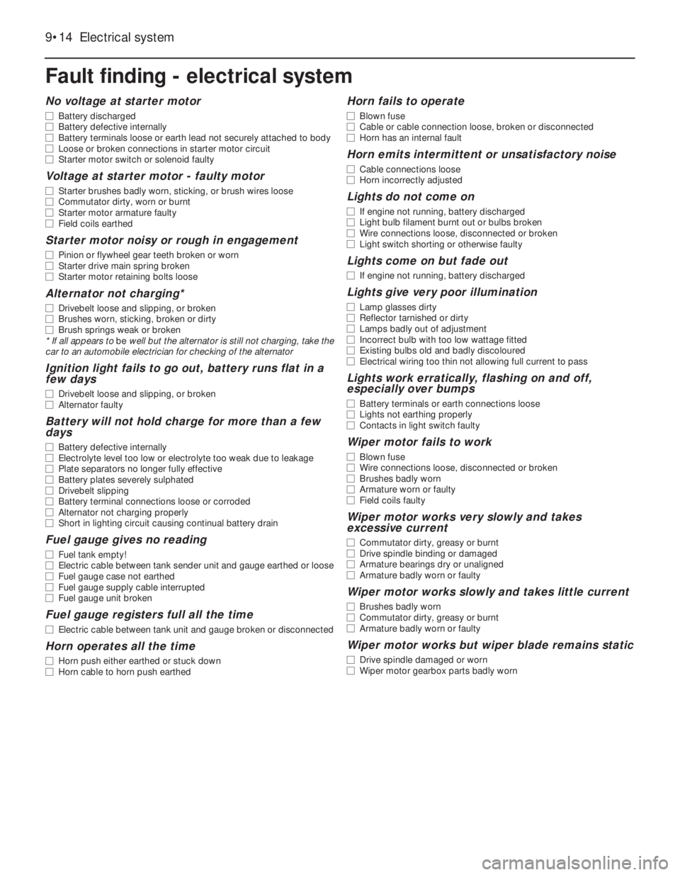
9•14 Electrical system
Fault finding - electrical system
No voltage at starter motor
m mBattery discharged
m mBattery defective internally
m mBattery terminals loose or earth lead not securely attached to body
m mLoose or broken connections in starter motor circuit
m mStarter motor switch or solenoid faulty
Voltage at starter motor - faulty motor
m
mStarter brushes badly worn, sticking, or brush wires loose
m mCommutator dirty, worn or burnt
m mStarter motor armature faulty
m mField coils earthed
Starter motor noisy or rough in engagement
m
mPinion or flywheel gear teeth broken or worn
m mStarter drive main spring broken
m mStarter motor retaining bolts loose
Alternator not charging*
m
mDrivebelt loose and slipping, or broken
m mBrushes worn, sticking, broken or dirty
m mBrush springs weak or broken
* If all appears to be well but the alternator is still not charging, take the
car to an automobile electrician for checking of the alternator
Ignition light fails to go out, battery runs flat in a
few days
m mDrivebelt loose and slipping, or broken
m mAlternator faulty
Battery will not hold charge for more than a few
days
m mBattery defective internally
m mElectrolyte level too low or electrolyte too weak due to leakage
m mPlate separators no longer fully effective
m mBattery plates severely sulphated
m mDrivebelt slipping
m mBattery terminal connections loose or corroded
m mAlternator not charging properly
m mShort in lighting circuit causing continual battery drain
Fuel gauge gives no reading
m
mFuel tank empty!
m mElectric cable between tank sender unit and gauge earthed or loose
m mFuel gauge case not earthed
m mFuel gauge supply cable interrupted
m mFuel gauge unit broken
Fuel gauge registers full all the time
m
mElectric cable between tank unit and gauge broken or disconnected
Horn operates all the time
m
mHorn push either earthed or stuck down
m mHorn cable to horn push earthed
Horn fails to operate
m
mBlown fuse
m mCable or cable connection loose, broken or disconnected
m mHorn has an internal fault
Horn emits intermittent or unsatisfactory noise
m
mCable connections loose
m mHorn incorrectly adjusted
Lights do not come on
m
mIf engine not running, battery discharged
m mLight bulb filament burnt out or bulbs broken
m mWire connections loose, disconnected or broken
m mLight switch shorting or otherwise faulty
Lights come on but fade out
m
mIf engine not running, battery discharged
Lights give very poor illumination
m
mLamp glasses dirty
m mReflector tarnished or dirty
m mLamps badly out of adjustment
m mIncorrect bulb with too low wattage fitted
m mExisting bulbs old and badly discoloured
m mElectrical wiring too thin not allowing full current to pass
Lights work erratically, flashing on and off,
especially over bumps
m mBattery terminals or earth connections loose
m mLights not earthing properly
m mContacts in light switch faulty
Wiper motor fails to work
m
mBlown fuse
m mWire connections loose, disconnected or broken
m mBrushes badly worn
m mArmature worn or faulty
m mField coils faulty
Wiper motor works very slowly and takes
excessive current
m mCommutator dirty, greasy or burnt
m mDrive spindle binding or damaged
m mArmature bearings dry or unaligned
m mArmature badly worn or faulty
Wiper motor works slowly and takes little current
m
mBrushes badly worn
m mCommutator dirty, greasy or burnt
m mArmature badly worn or faulty
Wiper motor works but wiper blade remains static
m
mDrive spindle damaged or worn
m mWiper motor gearbox parts badly worn
Page 115 of 303
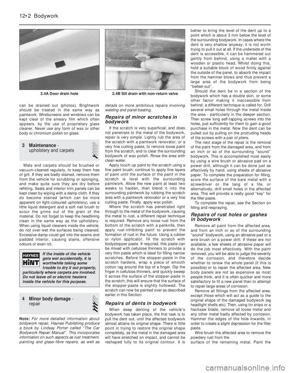
can be drained out (photos). Brightwork
should be treated in the same way as
paintwork. Windscreens and windows can be
kept clear of the smeary film which often
appears, by the use of proprietary glass
cleaner. Never use any form of wax or other
body or chromium polish on glass.
3 Maintenance-
upholstery and carpets
1
Mats and carpets should be brushed or
vacuum-cleaned regularly, to keep them free
of grit. If they are badly stained, remove them
from the vehicle for scrubbing or sponging,
and make quite sure they are dry before
refitting. Seats and interior trim panels can be
kept clean by wiping with a damp cloth. If they
do become stained (which can be more
apparent on light-coloured upholstery), use a
little liquid detergent and a soft nail brush to
scour the grime out of the grain of the
material. Do not forget to keep the headlining
clean in the same way as the upholstery.
When using liquid cleaners inside the vehicle,
do not over-wet the surfaces being cleaned.
Excessive damp could get into the seams and
padded interior, causing stains, offensive
odours or even rot.
4 Minor body damage-
repair
3
Note:For more detailed information about
bodywork repair, Haynes Publishing produce
a book by Lindsay Porter called “The Car
Bodywork Repair Manual”. This incorporates
information on such aspects as rust treatment,
painting and glass-fibre repairs, as well asdetails on more ambitious repairs involving
welding and panel beating.
Repairs of minor scratches in
bodywork
If the scratch is very superficial, and does
not penetrate to the metal of the bodywork,
repair is very simple. Lightly rub the area of
the scratch with a paintwork renovator, or a
very fine cutting paste, to remove loose paint
from the scratch, and to clear the surrounding
bodywork of wax polish. Rinse the area with
clean water.
Apply touch-up paint to the scratch using a
fine paint brush; continue to apply fine layers
of paint until the surface of the paint in the
scratch is level with the surrounding
paintwork. Allow the new paint at least two
weeks to harden, then blend it into the
surrounding paintwork by rubbing the scratch
area with a paintwork renovator or a very fine
cutting paste. Finally, apply wax polish.
Where the scratch has penetrated right
through to the metal of the bodywork, causing
the metal to rust, a different repair technique
is required. Remove any loose rust from the
bottom of the scratch with a penknife, then
apply rust-inhibiting paint to prevent the
formation of rust in the future. Using a rubber
or nylon applicator, fill the scratch with
bodystopper paste. If required, this paste can
be mixed with cellulose thinners to provide a
very thin paste which is ideal for filling narrow
scratches. Before the stopper-paste in the
scratch hardens, wrap a piece of smooth
cotton rag around the top of a finger. Dip the
finger in cellulose thinners, and quickly sweep
it across the surface of the stopper-paste in
the scratch; this will ensure that the surface of
the stopper-paste is slightly hollowed. The
scratch can now be painted over as described
earlier in this Section.
Repairs of dents in bodywork
When deep denting of the vehicle’s
bodywork has taken place, the first task is to
pull the dent out, until the affected bodywork
almost attains its original shape. There is little
point in trying to restore the original shape
completely, as the metal in the damaged area
will have stretched on impact, and cannot be
reshaped fully to its original contour. It isbetter to bring the level of the dent up to a
point which is about 3 mm below the level of
the surrounding bodywork. In cases where the
dent is very shallow anyway, it is not worth
trying to pull it out at all. If the underside of the
dent is accessible, it can be hammered out
gently from behind, using a mallet with a
wooden or plastic head. Whilst doing this,
hold a suitable block of wood firmly against
the outside of the panel, to absorb the impact
from the hammer blows and thus prevent a
large area of the bodywork from being
“belled-out”.
Should the dent be in a section of the
bodywork which has a double skin, or some
other factor making it inaccessible from
behind, a different technique is called for. Drill
several small holes through the metal inside
the area - particularly in the deeper section.
Then screw long self-tapping screws into the
holes, just sufficiently for them to gain a good
purchase in the metal. Now the dent can be
pulled out by pulling on the protruding heads
of the screws with a pair of pliers.
The next stage of the repair is the removal
of the paint from the damaged area, and from
an inch or so of the surrounding “sound”
bodywork. This is accomplished most easily
by using a wire brush or abrasive pad on a
power drill, although it can be done just as
effectively by hand, using sheets of abrasive
paper. To complete the preparation for filling,
score the surface of the bare metal with a
screwdriver or the tang of a file, or
alternatively, drill small holes in the affected
area. This will provide a really good “key” for
the filler paste.
To complete the repair, see the Section on
filling and respraying.
Repairs of rust holes or gashes
in bodywork
Remove all paint from the affected area,
and from an inch or so of the surrounding
“sound” bodywork, using an abrasive pad or a
wire brush on a power drill. If these are not
available, a few sheets of abrasive paper will
do the job most effectively. With the paint
removed, you will be able to judge the severity
of the corrosion, and therefore decide
whether to renew the whole panel (if this is
possible) or to repair the affected area. New
body panels are not as expensive as most
people think, and it is often quicker and more
satisfactory to fit a new panel than to attempt
to repair large areas of corrosion.
Remove all fittings from the affected area,
except those which will act as a guide to the
original shape of the damaged bodywork (eg
headlight shells etc). Then, using tin snips or a
hacksaw blade, remove all loose metal and
any other metal badly affected by corrosion.
Hammer the edges of the hole inwards, in
order to create a slight depression for the filler
paste.
Wire-brush the affected area to remove the
powdery rust from the
surface of the remaining metal. Paint the
12•2 Bodywork
2.4B Sill drain with non-return valve2.4A Door drain hole
If the inside of the vehicle
gets wet accidentally, it is
worthwhile taking some
trouble to dry it out properly,
particularly where carpets are involved.
Do not leave oil or electric heaters
inside the vehicle for this purpose.