ESP FIAT UNO 1983 Service Owner's Manual
[x] Cancel search | Manufacturer: FIAT, Model Year: 1983, Model line: UNO, Model: FIAT UNO 1983Pages: 303, PDF Size: 10.36 MB
Page 116 of 303
affected area with rust-inhibiting paint, if the
back of the rusted area is accessible, treat
this also.
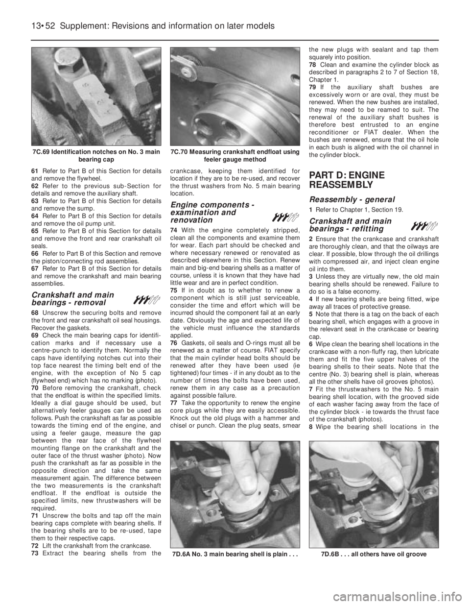
Before filling can take place, it will be
necessary to block the hole in some way. This
can be achieved by the use of aluminium or
plastic mesh, or aluminium tape.
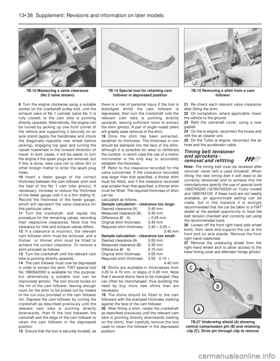
Aluminium or plastic mesh, or glass-fibre
matting, is probably the best material to use
for a large hole. Cut a piece to the
approximate size and shape of the hole to be
filled, then position it in the hole so that its
edges are below the level of the surrounding
bodywork. It can be retained in position by
several blobs of filler paste around its
periphery.
Aluminium tape should be used for small or
very narrow holes. Pull a piece off the roll, trim
it to the approximate size and shape required,
then pull off the backing paper (if used) and
stick the tape over the hole; it can be
overlapped if the thickness of one piece is
insufficient. Burnish down the edges of the
tape with the handle of a screwdriver or
similar, to ensure that the tape is securely
attached to the metal underneath.
Bodywork repairs - filling and
respraying
Before using this Section, see the Sections
on dent, deep scratch, rust holes and gash
repairs.
Many types of bodyfiller are available, but
generally speaking, those proprietary kits
which contain a tin of filler paste and a tube of
resin hardener are best for this type of repair. A
wide, flexible plastic or nylon applicator will be
found invaluable for imparting a smooth and
well-contoured finish to the surface of the filler.
Mix up a little filler on a clean piece of card
or board - measure the hardener carefully
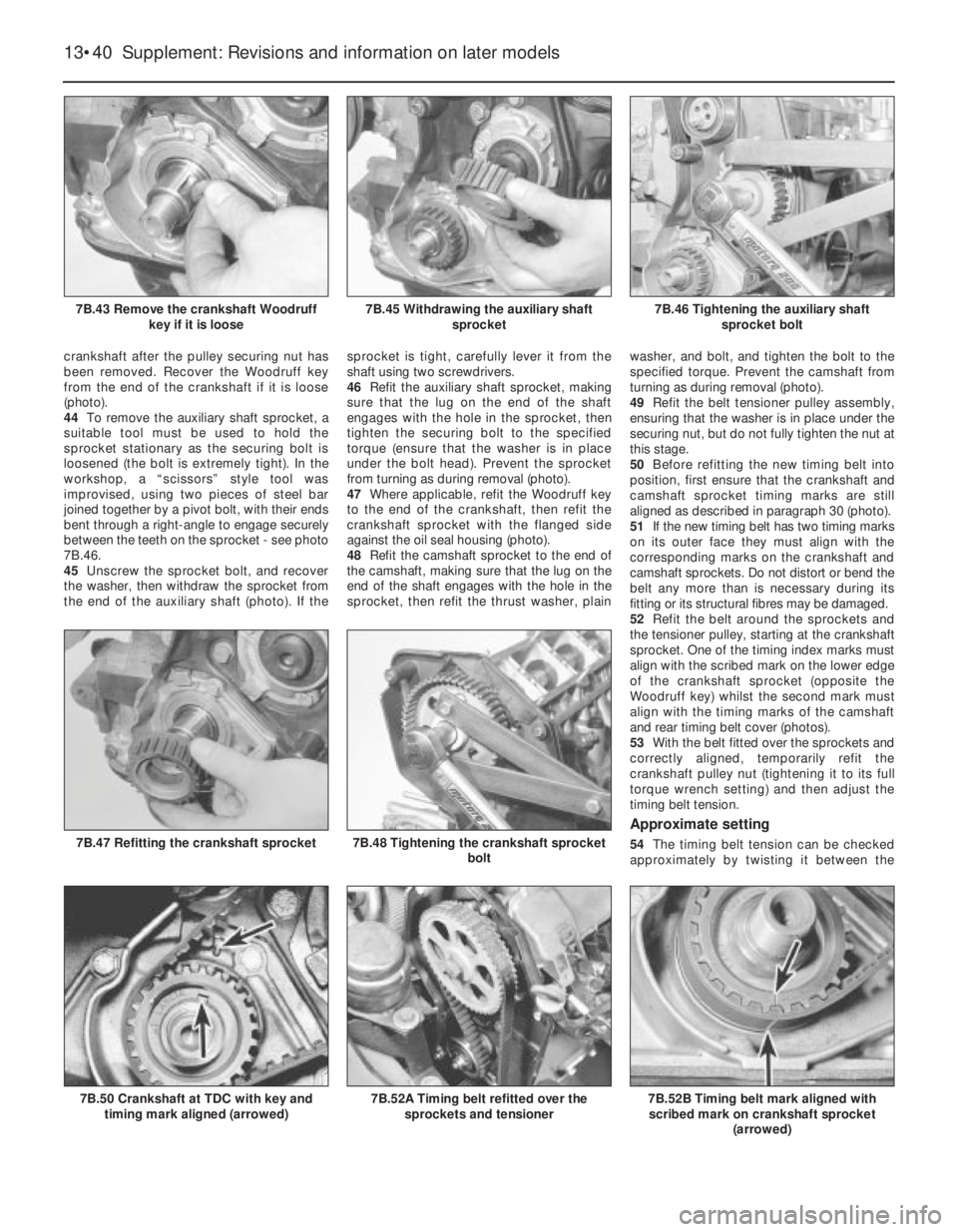
(follow the maker’s instructions on the pack),
otherwise the filler will set too rapidly or too
slowly. Using the applicator, apply the filler
paste to the prepared area; draw the
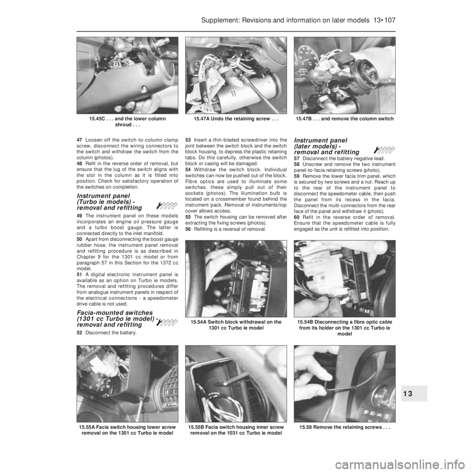
applicator across the surface of the filler to
achieve the correct contour and to level the
surface. As soon as a contour that
approximates to the correct one is achieved,
stop working the paste - if you carry on too
long, the paste will become sticky and begin
to “pick-up” on the applicator. Continue to
add thin layers of filler paste at 20-minute
intervals, until the level of the filler is just
proud of the surrounding bodywork.
Once the filler has hardened, the excess
can be removed using a metal plane or file.
From then on, progressively-finer grades of
abrasive paper should be used, starting with a
40-grade production paper, and finishing with
a 400-grade wet-and-dry paper. Always wrap
the abrasive paper around a flat rubber, cork,
or wooden block - otherwise the surface of
the filler will not be completely flat. During the
smoothing of the filler surface, the wet-and-
dry paper should be periodically rinsed in
water. This will ensure that a very smooth
finish is imparted to the filler at the final stage.At this stage, the “dent” should be
surrounded by a ring of bare metal, which in
turn should be encircled by the finely
“feathered” edge of the good paintwork.
Rinse the repair area with clean water, until all
of the dust produced by the rubbing-down
operation has gone.
Spray the whole area with a light coat of
primer - this will show up any imperfections in
the surface of the filler. Repair these
imperfections with fresh filler paste or
bodystopper, and once more smooth the
surface with abrasive paper. Repeat this
spray-and-repair procedure until you are
satisfied that the surface of the filler, and the
feathered edge of the paintwork, are perfect.
Clean the repair area with clean water, and
allow to dry fully.
The repair area is now ready for final
spraying. Paint spraying must be carried out
in a warm, dry, windless and dust-free
atmosphere. This condition can be created
artificially if you have access to a large indoor
working area, but if you are forced to work in
the open, you will have to pick your day very
carefully. If you are working indoors, dousing
the floor in the work area with water will help
to settle the dust which would otherwise be in
the atmosphere. If the repair area is confined
to one body panel, mask off the surrounding
panels; this will help to minimise the effects of
a slight mis-match in paint colours. Bodywork
fittings (eg chrome strips, door handles etc)
will also need to be masked off. Use genuine
masking tape, and several thicknesses of
newspaper, for the masking operations.
Before commencing to spray, agitate the
aerosol can thoroughly, then spray a test area
(an old tin, or similar) until the technique is
mastered. Cover the repair area with a thick
coat of primer; the thickness should be built
up using several thin layers of paint, rather
than one thick one. Using 400-grade wet-and-
dry paper, rub down the surface of the primer
until it is really smooth. While doing this, the
work area should be thoroughly doused withwater, and the wet-and-dry paper periodically
rinsed in water. Allow to dry before spraying
on more paint.
Spray on the top coat, again building up the
thickness by using several thin layers of paint.
Start spraying at one edge of the repair area,
and then, using a side-to-side motion, work
until the whole repair area and about 2 inches
of the surrounding original paintwork is
covered. Remove all masking material 10 to 15
minutes after spraying on the final coat of
paint.
Allow the new paint at least two weeks to
harden, then, using a paintwork renovator, or
a very fine cutting paste, blend the edges of
the paint into the existing paintwork. Finally,
apply wax polish.
5 Major body damage-
repair
5
1Major repair to the body should be left to
your Fiat dealer or specialist body repairer.
2Special jigs and alignment gauges are
required without which steering and
suspension characteristics may be incorrect
after the repairs are completed.
6 Radiator grille-
removal and refitting
1
1Open the bonnet.
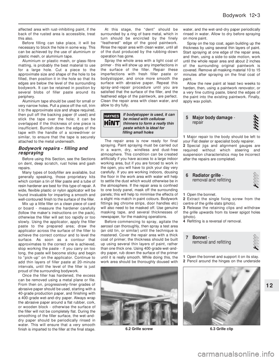
2Extract the single fixing screw from the
centre of the grille slats (photo).
3Release the retaining clips and withdraw
the grille upwards from its lower spigot holes
(photo).
4Refitting is a reversal of removal.
7 Bonnet-
removal and refitting
1
1Open the bonnet and support it on its stay.
2Pencil around the hinges on the underside
Bodywork 12•3
12
If bodystopper is used, it can
be mixed with cellulose
thinners to form a really thin
paste which is ideal for
filling small holes
6.3 Grille clip6.2 Grille screw
Page 150 of 303
75If the pump is unworn, refit the rear cover
plate and tighten the screws fully.
76Apply air pressure from a tyre pump to the
oil pump oil ducts to clear any sludge or other
material and then prime the pump by pouring
clean engine oil into its intake duct at the
same time turning the oil pump inner gear with
the fingers.
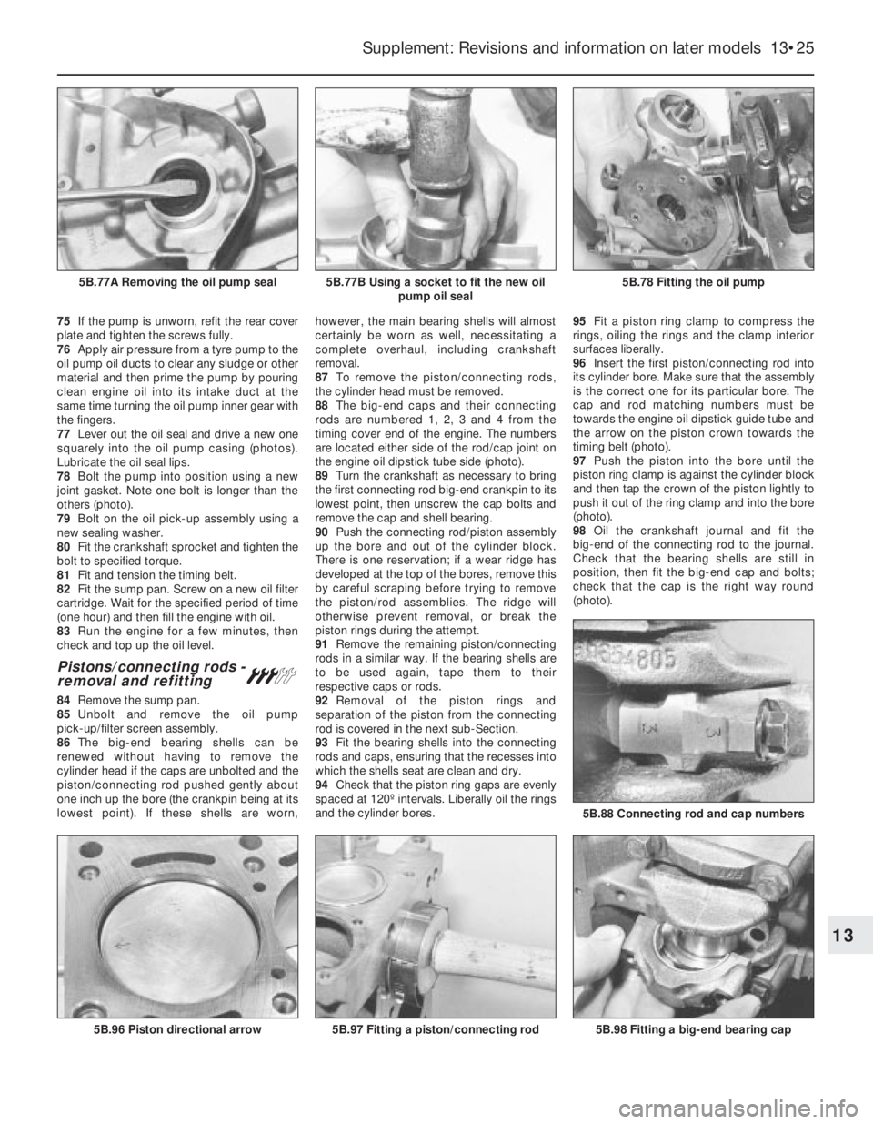
77Lever out the oil seal and drive a new one
squarely into the oil pump casing (photos).
Lubricate the oil seal lips.
78Bolt the pump into position using a new
joint gasket. Note one bolt is longer than the
others (photo).
79Bolt on the oil pick-up assembly using a
new sealing washer.
80Fit the crankshaft sprocket and tighten the
bolt to specified torque.
81Fit and tension the timing belt.
82Fit the sump pan. Screw on a new oil filter
cartridge. Wait for the specified period of time
(one hour) and then fill the engine with oil.
83Run the engine for a few minutes, then
check and top up the oil level.
Pistons/connecting rods -
removal and refitting#
84Remove the sump pan.
85Unbolt and remove the oil pump
pick-up/filter screen assembly.
86The big-end bearing shells can be
renewed without having to remove the
cylinder head if the caps are unbolted and the
piston/connecting rod pushed gently about
one inch up the bore (the crankpin being at its
lowest point). If these shells are worn,however, the main bearing shells will almost
certainly be worn as well, necessitating a
complete overhaul, including crankshaft
removal.
87To remove the piston/connecting rods,
the cylinder head must be removed.
88The big-end caps and their connecting
rods are numbered 1, 2, 3 and 4 from the
timing cover end of the engine. The numbers
are located either side of the rod/cap joint on
the engine oil dipstick tube side (photo).
89Turn the crankshaft as necessary to bring
the first connecting rod big-end crankpin to its
lowest point, then unscrew the cap bolts and
remove the cap and shell bearing.
90Push the connecting rod/piston assembly
up the bore and out of the cylinder block.
There is one reservation; if a wear ridge has
developed at the top of the bores, remove this
by careful scraping before trying to remove
the piston/rod assemblies. The ridge will
otherwise prevent removal, or break the
piston rings during the attempt.
91Remove the remaining piston/connecting
rods in a similar way. If the bearing shells are
to be used again, tape them to their
respective caps or rods.
92Removal of the piston rings and
separation of the piston from the connecting
rod is covered in the next sub-Section.
93Fit the bearing shells into the connecting
rods and caps, ensuring that the recesses into
which the shells seat are clean and dry.
94Check that the piston ring gaps are evenly
spaced at 120º intervals. Liberally oil the rings
and the cylinder bores.95Fit a piston ring clamp to compress the
rings, oiling the rings and the clamp interior
surfaces liberally.
96Insert the first piston/connecting rod into
its cylinder bore. Make sure that the assembly
is the correct one for its particular bore. The
cap and rod matching numbers must be
towards the engine oil dipstick guide tube and
the arrow on the piston crown towards the
timing belt (photo).
97Push the piston into the bore until the
piston ring clamp is against the cylinder block
and then tap the crown of the piston lightly to
push it out of the ring clamp and into the bore
(photo).
98Oil the crankshaft journal and fit the
big-end of the connecting rod to the journal.
Check that the bearing shells are still in
position, then fit the big-end cap and bolts;
check that the cap is the right way round
(photo).
Supplement: Revisions and information on later models 13•25
5B.78 Fitting the oil pump5B.77B Using a socket to fit the new oil
pump oil seal5B.77A Removing the oil pump seal
5B.98 Fitting a big-end bearing cap
5B.88 Connecting rod and cap numbers
5B.97 Fitting a piston/connecting rod5B.96 Piston directional arrow
13
Page 155 of 303
crankcase. If the shells are to be used again,
keep them with their respective bearing caps.
70The thrust washers which control
crankshaft endfloat are located in the
crankcase, and retained by the turned-over
edges of the centre main bearing shell.
71The engine is now fully stripped.
Examination and renovation
72The procedures for the following items are
essentially as described in Chapter 1, Sec-
tion 18.
Cylinder block and crankcase
Crankshaft and bearings
Flywheel
Oil seals and gaskets
Cylinder head
73Using a straight-edge, check the cylinder
head gasket surface for distortion. If it
exceeds the specified tolerance, it must be
surface ground by your dealer.74Refer to Chapter 1, Section 39, for
dismantling and renovation operations. Note
that single valve springs are fitted.
Oil pump
75Checking operations are described in
sub-Section B.
Pistons and connecting rods
76Refer to sub-Section B.
77If one or more connecting rods are
changed, it is important that its weight is
identical to that of the original. Use an
accurate balance to weigh them and remove
metal if necessary from the new rod in the
areas indicated in Fig. 13.7.
Camshaft and cam followers
78If the camshaft journals or bearings show
any sign of wear or scoring, then the
camshaft, or cylinder head, or both must be
renewed.
79The cam followers should be checked for
ovality using a micrometer. Unless unworn
they should be renewed.
Timing belt tensioner and timing belt
80The tensioner is a lubricant-sealed pulley,
and it should be tested for smooth and quiet
operation by turning it with the fingers. Any
evidence of roughness or rattle will indicate
the need for a new assembly (photo).81The timing belt should be inspected at
regular intervals for correct adjustment and
condition (see Section 3 or “Routine
maintenance” at the beginning of the Manual).
If there is evidence of worn teeth, cracking or
fraying, or oil contamination, renew the belt.
The vehicle manufacturers recommend that
the belt is renewed whenever it is removed,
and it should certainly be renewed at the
intervals specified in Section 3 or the main
“Routine maintenance” section at the
beginning of this Manual as a precautionary
measure against belt breakage and
consequent expensive engine damage.
PART D:
ENGINE REASSEMBLY AND
REFITTING
Reassembly - general
1Refer to Chapter 1, Section 19.
Complete reassembly#
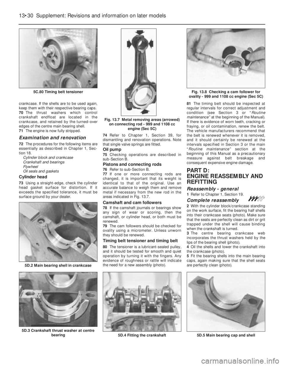
2With the cylinder block/crankcase standing
on the work surface, fit the bearing half shells
into their crankcase seats (photo). Make sure
that the seats are perfectly clean as dirt or grit
trapped under the shell will cause binding
when the crankshaft is turned.
3The centre bearing crankcase web
incorporates the thrust washers held by the
lips of the bearing shell (photo).
4Oil the shells and lower the crankshaft into
the crankcase (photo).
5Fit the bearing shells into the main bearing
caps, again making sure that the shell seats
are perfectly clean (photo).
13•30 Supplement: Revisions and information on later models
5D.5 Main bearing cap and shell5D.4 Fitting the crankshaft5D.3 Crankshaft thrust washer at centre
bearing
5D.2 Main bearing shell in crankcase
Fig. 13.8 Checking a cam follower for
ovality - 999 and 1108 cc engine (Sec 5C)
Fig. 13.7 Metal removing areas (arrowed)
on connecting rod - 999 and 1108 cc
engine (Sec 5C)
5C.80 Timing belt tensioner
Page 158 of 303
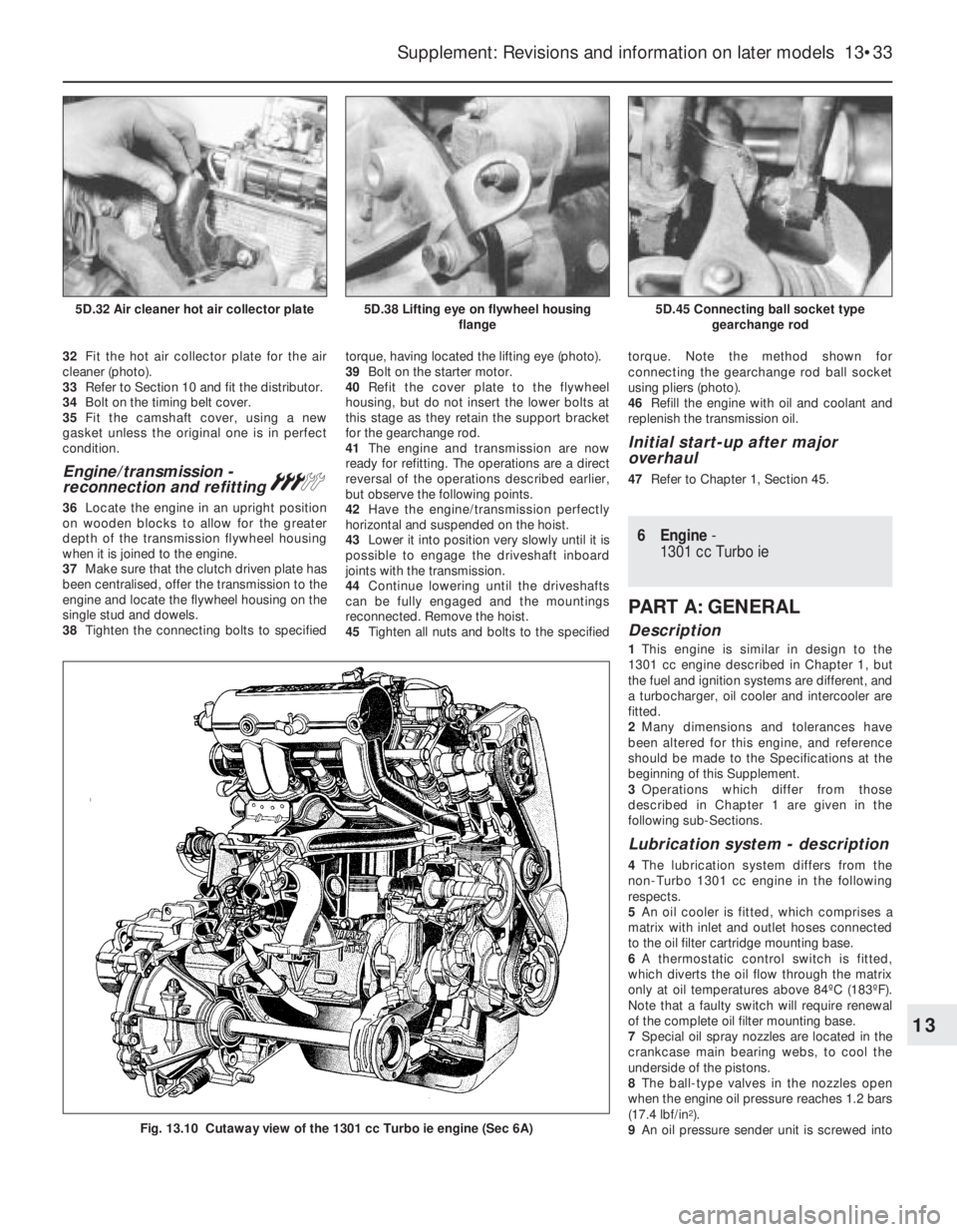
32Fit the hot air collector plate for the air
cleaner (photo).
33Refer to Section 10 and fit the distributor.
34Bolt on the timing belt cover.
35Fit the camshaft cover, using a new
gasket unless the original one is in perfect
condition.
Engine/transmission -
reconnection and refitting#
36Locate the engine in an upright position
on wooden blocks to allow for the greater
depth of the transmission flywheel housing
when it is joined to the engine.
37Make sure that the clutch driven plate has
been centralised, offer the transmission to the
engine and locate the flywheel housing on the
single stud and dowels.
38Tighten the connecting bolts to specifiedtorque, having located the lifting eye (photo).
39Bolt on the starter motor.
40Refit the cover plate to the flywheel
housing, but do not insert the lower bolts at
this stage as they retain the support bracket
for the gearchange rod.
41The engine and transmission are now
ready for refitting. The operations are a direct
reversal of the operations described earlier,
but observe the following points.
42Have the engine/transmission perfectly
horizontal and suspended on the hoist.
43Lower it into position very slowly until it is
possible to engage the driveshaft inboard
joints with the transmission.
44Continue lowering until the driveshafts
can be fully engaged and the mountings
reconnected. Remove the hoist.
45Tighten all nuts and bolts to the specifiedtorque. Note the method shown for
connecting the gearchange rod ball socket
using pliers (photo).
46Refill the engine with oil and coolant and
replenish the transmission oil.
Initial start-up after major
overhaul
47Refer to Chapter 1, Section 45.
6 Engine-
1301 cc Turbo ie
PART A: GENERAL
Description
1This engine is similar in design to the
1301 cc engine described in Chapter 1, but
the fuel and ignition systems are different, and
a turbocharger, oil cooler and intercooler are
fitted.
2Many dimensions and tolerances have
been altered for this engine, and reference
should be made to the Specifications at the
beginning of this Supplement.
3Operations which differ from those
described in Chapter 1 are given in the
following sub-Sections.
Lubrication system - description
4The lubrication system differs from the
non-Turbo 1301 cc engine in the following
respects.
5An oil cooler is fitted, which comprises a
matrix with inlet and outlet hoses connected
to the oil filter cartridge mounting base.
6A thermostatic control switch is fitted,
which diverts the oil flow through the matrix
only at oil temperatures above 84ºC (183ºF).
Note that a faulty switch will require renewal
of the complete oil filter mounting base.
7Special oil spray nozzles are located in the
crankcase main bearing webs, to cool the
underside of the pistons.
8The ball-type valves in the nozzles open
when the engine oil pressure reaches 1.2 bars
(17.4 lbf/in
2).
9An oil pressure sender unit is screwed into
Supplement: Revisions and information on later models 13•33
5D.45 Connecting ball socket type
gearchange rod5D.38 Lifting eye on flywheel housing
flange5D.32 Air cleaner hot air collector plate
Fig. 13.10 Cutaway view of the 1301 cc Turbo ie engine (Sec 6A)
13
Page 163 of 303
9Turn the engine clockwise using a suitable
socket on the crankshaft pulley bolt, until the
exhaust valve of No 1 cylinder (valve No 1) is
fully closed; ie the cam lobe is pointing
directly upwards. Alternatively, the engine can
be turned by jacking up one front corner of
the vehicle and supporting it securely on an
axle stand (apply the handbrake and chock
the diagonally-opposite rear wheel before
jacking), engaging top gear and turning the
raised roadwheel in the forward direction of
travel. In both cases, it will be easier to turn
the engine if the spark plugs are removed, but
if this is done, take care not to allow dirt or
other foreign matter to enter the spark plug
holes.
10Insert a feeler gauge of the correct
thickness between the cam follower shim and
the heel of the No 1 cam lobe (photo). If
necessary, increase or reduce the thickness
of the feeler gauge until it is a firm sliding fit.
Record the thickness of the feeler gauge,
which will represent the valve clearance for
this particular valve.
11Turn the crankshaft, and repeat the
procedure for the remaining valves, recording
their respective clearances. Note that the
clearance for inlet and exhaust valves differs.
12If a clearance is incorrect, the relevant
cam follower shim must be removed, and a
thicker or thinner shim must be fitted to
achieve the correct clearance. To remove a
shim proceed as follows.
13Turn the crankshaft until the relevant cam
lobe is pointing directly upwards.
14The cam follower must now be depressed
in order to extract the shim. FIAT special tool
No 1860642000 is available for this purpose,
but alternatively a suitable tool can be
improvised (photo). The tool should locate on
the rim of the cam follower, leaving enough
room for the shim to be prised out by means
of the cut-outs provided in the cam follower
rim. Depress the cam follower by turning the
crankshaft as described previously until the
relevant cam lobe is pointing directly
downwards, then fit the tool between the
camshaft and the edge of the cam follower to
retain the cam follower in the depressed
position.
15Ensure that the tool is securely located, asthere is a risk of personal injury if the tool is
dislodged whilst the cam follower is
depressed, then turn the crankshaft until the
relevant cam lobe is pointing directly
upwards, leaving sufficient room to extract
the shim (photo). A pair of angle-nosed pliers
will greatly ease removal of the shim.
16Once the shim has been extracted,
establish its thickness. The thickness in mm
should be stamped into the face of the shim,
although it is possible for wear to obliterate
the number, in which case the use of a metric
micrometer is the only way to accurately
establish the thickness.
17Refer to the clearance recorded for the
valve concerned. If the clearance recorded
was larger than that specified, a thicker shim
must be fitted, and if the clearance recorded
was smaller than that specified, a thinner shim
must be fitted. The required thickness of shim
can be
calculated as follows.
Sample calculation - clearance too large:
Desired clearance (A) 0.40 mm
Measured clearance (B) 0.45 mm
Difference (B - A) + 0.05 mm
Original shim thickness 3.40 mm
Required shim thickness 3.40 + 0.05 =
3.45 mm
Sample calculation - clearance too small:
Desired clearance (A) 0.50 mm
Measured clearance (B) 0.35 mm
Difference (B - A) 0.15 mm
Original shim thickness 4.55 mm
Required shim thickness 4.55 - 0.15 =
4.40 mm
18Shims are available in thicknesses from
3.20 to 4.70 mm, in steps of 0.05 mm. Note
that if several shims have to be changed, they
can often be interchanged, thus avoiding the
need by buy more new shims than are
necessary.
19The shims should be fitted to the cam
followers with the stamped thickness marking
against the face of the cam follower.
20After fitting a shim, rotate the crankshaft
as described previously until the relevant cam
lobe is pointing directly downwards (resting
on the shim), then carefully remove the tool
used to retain the follower in the depressed
position.21Re-check each relevant valve clearance
after fitting the shim.
22On completion, where applicable, lower
the vehicle to the ground.
23Refit the camshaft cover, using a new
gasket.
24On the ie engine, reconnect the hoses and
refit the air cleaner unit.
25On the Turbo ie engine, reconnect the air
hose and the accelerator cable.
Timing belt tensioner
and sprockets -
removal and refitting
#
Note: The timing belt must be renewed after
removal: never refit a used drivebelt. When
fitting the new timing belt it will need to be
correctly tensioned and to achieve this the
manufacturers specify the use of special tools
1860745200 (18760745300 on Turbo model)
and 1860745100. If these tools are not readily
available, an approximate setting can be
made, but in this instance it is strongly
recommended that the car be taken to a FIAT
dealer at the earliest opportunity to have the
belt tension checked and correctly set using
the recommended tools.
26Loosen off the front right-hand side wheel
bolts, then raise and support the car at the
front end on axle stands. Remove the front
right-hand roadwheel.
27Remove the underwing shield from the
right-hand wheel arch to allow access to the
lower timing cover and alternator fixings (photo).
13•38 Supplement: Revisions and information on later models
7B.27 Underwing shield (A) showing
central compression pin (B) and retaining
clip (C). Drive pin through clip to remove
7B.15 Removing a shim from a cam
follower7B.14 Special tool for retaining cam
follower in depressed position7B.10 Measuring a valve clearance
(No 2 valve shown)
Page 165 of 303
crankshaft after the pulley securing nut has
been removed. Recover the Woodruff key
from the end of the crankshaft if it is loose
(photo).
44To remove the auxiliary shaft sprocket, a
suitable tool must be used to hold the
sprocket stationary as the securing bolt is
loosened (the bolt is extremely tight). In the
workshop, a “scissors” style tool was
improvised, using two pieces of steel bar
joined together by a pivot bolt, with their ends
bent through a right-angle to engage securely
between the teeth on the sprocket - see photo
7B.46.
45Unscrew the sprocket bolt, and recover
the washer, then withdraw the sprocket from
the end of the auxiliary shaft (photo). If thesprocket is tight, carefully lever it from the
shaft using two screwdrivers.
46Refit the auxiliary shaft sprocket, making
sure that the lug on the end of the shaft
engages with the hole in the sprocket, then
tighten the securing bolt to the specified
torque (ensure that the washer is in place
under the bolt head). Prevent the sprocket
from turning as during removal (photo).
47Where applicable, refit the Woodruff key
to the end of the crankshaft, then refit the
crankshaft sprocket with the flanged side
against the oil seal housing (photo).
48Refit the camshaft sprocket to the end of
the camshaft, making sure that the lug on the
end of the shaft engages with the hole in the
sprocket, then refit the thrust washer, plainwasher, and bolt, and tighten the bolt to the
specified torque. Prevent the camshaft from
turning as during removal (photo).
49Refit the belt tensioner pulley assembly,
ensuring that the washer is in place under the
securing nut, but do not fully tighten the nut at
this stage.
50Before refitting the new timing belt into
position, first ensure that the crankshaft and
camshaft sprocket timing marks are still
aligned as described in paragraph 30 (photo).
51If the new timing belt has two timing marks
on its outer face they must align with the
corresponding marks on the crankshaft and
camshaft sprockets. Do not distort or bend the
belt any more than is necessary during its
fitting or its structural fibres may be damaged.
52Refit the belt around the sprockets and
the tensioner pulley, starting at the crankshaft
sprocket. One of the timing index marks must
align with the scribed mark on the lower edge
of the crankshaft sprocket (opposite the
Woodruff key) whilst the second mark must
align with the timing marks of the camshaft
and rear timing belt cover (photos).
53With the belt fitted over the sprockets and
correctly aligned, temporarily refit the
crankshaft pulley nut (tightening it to its full
torque wrench setting) and then adjust the
timing belt tension.
Approximate setting
54The timing belt tension can be checked
approximately by twisting it between the
13•40 Supplement: Revisions and information on later models
7B.52B Timing belt mark aligned with
scribed mark on crankshaft sprocket
(arrowed)7B.52A Timing belt refitted over the
sprockets and tensioner7B.50 Crankshaft at TDC with key and
timing mark aligned (arrowed)
7B.48 Tightening the crankshaft sprocket
bolt7B.47 Refitting the crankshaft sprocket
7B.46 Tightening the auxiliary shaft
sprocket bolt7B.45 Withdrawing the auxiliary shaft
sprocket7B.43 Remove the crankshaft Woodruff
key if it is loose
Page 177 of 303
61Refer to Part B of this Section for details
and remove the flywheel.
62Refer to the previous sub-Section for
details and remove the auxiliary shaft.
63Refer to Part B of this Section for details
and remove the sump.
64Refer to Part B of this Section for details
and remove the oil pump unit.
65Refer to Part B of this Section for details
and remove the front and rear crankshaft oil
seals.
66Refer to Part B of this Section and remove
the piston/connecting rod assemblies.
67Refer to Part B of this Section for details
and remove the crankshaft and main bearing
assemblies.
Crankshaft and main
bearings - removal#
68Unscrew the securing bolts and remove
the front and rear crankshaft oil seal housings.
Recover the gaskets.
69Check the main bearing caps for identifi-
cation marks and if necessary use a
centre-punch to identify them. Normally the
caps have identifying notches cut into their
top face nearest the timing belt end of the
engine, with the exception of No 5 cap
(flywheel end) which has no marking (photo).
70Before removing the crankshaft, check
that the endfloat is within the specified limits.
Ideally a dial gauge should be used, but
alternatively feeler gauges can be used as
follows. Push the crankshaft as far as possible
towards the timing end of the engine, and
using a feeler gauge, measure the gap
between the rear face of the flywheel
mounting flange on the crankshaft and the
outer face of the thrust washer (photo). Now
push the crankshaft as far as possible in the
opposite direction and take the same
measurement again. The difference between
the two measurements is the crankshaft
endfloat. If the endfloat is outside the
specified limits, new thrustwashers will be
required.
71Unscrew the bolts and tap off the main
bearing caps complete with bearing shells. If
the bearing shells are to be re-used, tape
them to their respective caps.
72Lift the crankshaft from the crankcase.
73Extract the bearing shells from thecrankcase, keeping them identified for
location if they are to be re-used, and recover
the thrust washers from No. 5 main bearing
location.
Engine components -
examination and
renovation
#
74With the engine completely stripped,
clean all the components and examine them
for wear. Each part should be checked and
where necessary renewed or renovated as
described elsewhere in this Section. Renew
main and big-end bearing shells as a matter of
course, unless it is known that they have had
little wear and are in perfect condition.
75If in doubt as to whether to renew a
component which is still just serviceable,
consider the time and effort which will be
incurred should the component fail at an early
date. Obviously the age and expected life of
the vehicle must influence the standards
applied.
76Gaskets, oil seals and O-rings must all be
renewed as a matter of course. FIAT specify
that the main cylinder head bolts should be
renewed after they have been used (ie
tightened) four times - if in any doubt as to the
number of times the bolts have been used,
renew them in any case as a precaution
against possible failure.
77Take the opportunity to renew the engine
core plugs while they are easily accessible.
Knock out the old plugs with a hammer and
chisel or punch. Clean the plug seats, smearthe new plugs with sealant and tap them
squarely into position.
78Clean and examine the cylinder block as
described in paragraphs 2 to 7 of Section 18,
Chapter 1.
79If the auxiliary shaft bushes are
excessively worn or are oval, they must be
renewed. When the new bushes are installed,
they may need to be reamed to suit. The
renewal of the auxiliary shaft bushes is
therefore best entrusted to an engine
reconditioner or FIAT dealer. When the
bushes are renewed, ensure that the oil hole
in each bush is aligned with the oil channel in
the cylinder block.
PART D: ENGINE
REASSEMBLY
Reassembly - general
1Refer to Chapter 1, Section 19.
Crankshaft and main
bearings - refitting#
2Ensure that the crankcase and crankshaft
are thoroughly clean, and that the oilways are
clear. If possible, blow through the oil drillings
with compressed air, and inject clean engine
oil into them.
3Unless they are virtually new, the old main
bearing shells should be renewed. Failure to
do so is a false economy.
4If new bearing shells are being fitted, wipe
away all traces of protective grease.
5Note that there is a tag on the back of each
bearing shell, which engages with a groove in
the relevant seat in the crankcase or bearing
cap.
6Wipe clean the bearing shell locations in the
crankcase with a non-fluffy rag, then lubricate
them and fit the five upper halves of the
bearing shells to their seats. Note that the
centre (No. 3) bearing shell is plain, whereas
all the other shells have oil grooves (photos).
7Fit the thrustwashers to the No. 5 main
bearing shell location, with the grooved side
of each washer facing away from the face of
the cylinder block - ie towards the thrust face
of the crankshaft (photos).
8Wipe the bearing shell locations in the
13•52 Supplement: Revisions and information on later models
7D.6B . . . all others have oil groove7D.6A No. 3 main bearing shell is plain . . .
7C.70 Measuring crankshaft endfloat using
feeler gauge method7C.69 Identification notches on No. 3 main
bearing cap
Page 232 of 303
47Loosen off the switch-to-column clamp
screw, disconnect the wiring connectors to
the switch and withdraw the switch from the
column (photos).
48Refit in the reverse order of removal, but
ensure that the lug of the switch aligns with
the slot in the column as it is fitted into
position. Check for satisfactory operation of
the switches on completion.
Instrument panel
(Turbo ie models) -
removal and refitting
Á
49The instrument panel on these models
incorporates an engine oil pressure gauge
and a turbo boost gauge. The latter is
connected directly to the inlet manifold.
50Apart from disconnecting the boost gauge
rubber hose, the instrument panel removal
and refitting procedure is as described in
Chapter 9 for the 1301 cc model or from
paragraph 57 in this Section for the 1372 cc
model.
51A digital electronic instrument panel is
available as an option on Turbo ie models.
The removal and refitting procedures differ
from analogue instrument panels in respect of
the electrical connections - a speedometer
drive cable is not used.
Facia-mounted switches
(1301 cc Turbo ie model) -
removal and refitting
Á
52Disconnect the battery.53Insert a thin-bladed screwdriver into the
joint between the switch block and the switch
block housing, to depress the plastic retaining
tabs. Do this carefully, otherwise the switch
block or casing will be damaged.
54Withdraw the switch block. Individual
switches can now be pushed out of the block.
Fibre optics are used to illuminate some
switches, these simply pull out of their
sockets (photos). The illumination bulb is
located on a crossmember found behind the
instrument pack. Removal of instruments/top
cover allows access.
55The switch housing can be removed after
extracting the fixing screws (photos).
56Refitting is a reversal of removal.
Instrument panel
(later models) -
removal and refitting
Á57Disconnect the battery negative lead.
58Unscrew and remove the two instrument
panel-to-facia retaining screws (photo).
59Remove the lower facia trim panel, which
is secured by two screws and a nut. Reach up
to the rear of the instrument panel to
disconnect the speedometer cable, then push
the panel from its recess in the facia.
Disconnect the multi-connectors from the rear
face of the panel and withdraw it (photo).
60Refit in the reverse order of removal.
Ensure that the speedometer cable is fully
engaged as the unit is refitted into position.
Supplement: Revisions and information on later models 13•107
15.47B . . . and remove the column switch15.47A Undo the retaining screw . . .15.45C . . . and the lower column
shroud . . .
15.58 Remove the retaining screws . . .15.55B Facia switch housing inner screw
removal on the 1031 cc Turbo ie model
15.54B Disconnecting a fibre optic cable
from its holder on the 1301 cc Turbo ie
model15.54A Switch block withdrawal on the
1301 cc Turbo ie model
15.55A Facia switch housing lower screw
removal on the 1301 cc Turbo ie model
13
Page 233 of 303
Auxiliary control panel
(later models) -
removal and refitting
Á
61Disconnect the battery negative lead.
62Insert the flat of a screwdriver under the
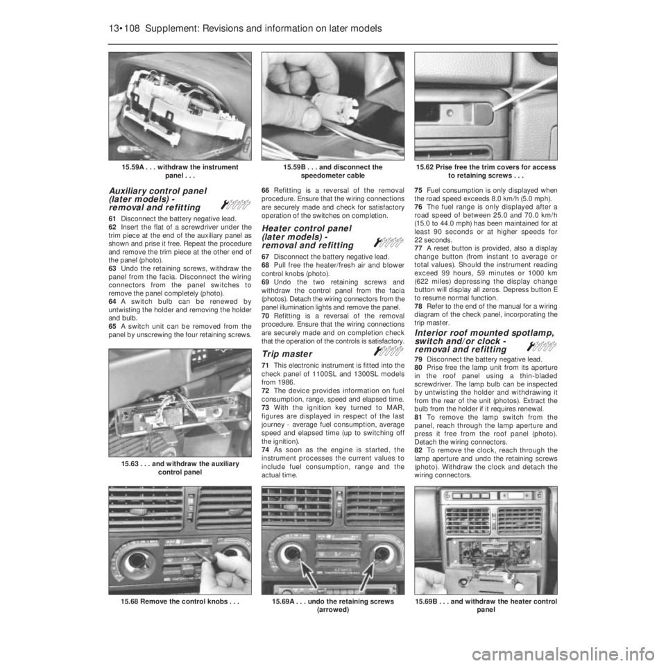
trim piece at the end of the auxiliary panel as
shown and prise it free. Repeat the procedure
and remove the trim piece at the other end of
the panel (photo).
63Undo the retaining screws, withdraw the
panel from the facia. Disconnect the wiring
connectors from the panel switches to
remove the panel completely (photo).
64A switch bulb can be renewed by
untwisting the holder and removing the holder
and bulb.
65A switch unit can be removed from the
panel by unscrewing the four retaining screws.66Refitting is a reversal of the removal
procedure. Ensure that the wiring connections
are securely made and check for satisfactory
operation of the switches on completion.
Heater control panel
(later models) -
removal and refitting
Á
67Disconnect the battery negative lead.
68Pull free the heater/fresh air and blower
control knobs (photo).
69Undo the two retaining screws and
withdraw the control panel from the facia
(photos). Detach the wiring connectors from the
panel illumination lights and remove the panel.
70Refitting is a reversal of the removal
procedure. Ensure that the wiring connections
are securely made and on completion check
that the operation of the controls is satisfactory.
Trip master Á
71This electronic instrument is fitted into the
check panel of 1100SL and 1300SL models
from 1986.
72The device provides information on fuel
consumption, range, speed and elapsed time.
73With the ignition key turned to MAR,
figures are displayed in respect of the last
journey - average fuel consumption, average
speed and elapsed time (up to switching off
the ignition).
74As soon as the engine is started, the
instrument processes the current values to
include fuel consumption, range and the
actual time. 75Fuel consumption is only displayed when
the road speed exceeds 8.0 km/h (5.0 mph).
76The fuel range is only displayed after a
road speed of between 25.0 and 70.0 km/h
(15.0 to 44.0 mph) has been maintained for at
least 90 seconds or at higher speeds for
22 seconds.
77A reset button is provided, also a display
change button (from instant to average or
total values). Should the instrument reading
exceed 99 hours, 59 minutes or 1000 km
(622 miles) depressing the display change
button will display all zeros. Depress button E
to resume normal function.
78Refer to the end of the manual for a wiring
diagram of the check panel, incorporating the
trip master.
Interior roof mounted spotlamp,
switch and/or clock -
removal and refitting
Á
79Disconnect the battery negative lead.
80Prise free the lamp unit from its aperture
in the roof panel using a thin-bladed
screwdriver. The lamp bulb can be inspected
by untwisting the holder and withdrawing it
from the rear of the unit (photos). Extract the
bulb from the holder if it requires renewal.
81To remove the lamp switch from the
panel, reach through the lamp aperture and
press it free from the roof panel (photo).
Detach the wiring connectors.
82To remove the clock, reach through the
lamp aperture and undo the retaining screws
(photo). Withdraw the clock and detach the
wiring connectors.
13•108 Supplement: Revisions and information on later models
15.69B . . . and withdraw the heater control
panel15.69A . . . undo the retaining screws
(arrowed)15.68 Remove the control knobs . . .
15.63 . . . and withdraw the auxiliary
control panel
15.62 Prise free the trim covers for access
to retaining screws . . .15.59B . . . and disconnect the
speedometer cable15.59A . . . withdraw the instrument
panel . . .
Page 292 of 303
Fault FindingREF•9
REF
Introduction
The vehicle owner who does his or her own
maintenance according to the recommended
schedules should not have to use this section
of the manual very often. Modern component
reliability is such that, provided those items
subject to wear or deterioration are inspected
or renewed at the specified intervals, sudden
failure is comparatively rare. Faults do not
usually just happen as a result of sudden
failure, but develop over a period of time.
Major mechanical failures in particular are
usually preceded by characteristic symptoms
over hundreds or even thousands of miles.
Those components which do occasionally fail
without warning are often small and easily
carried in the vehicle.
With any fault finding, the first step is to
decide where to begin investigations.
Sometimes this is obvious, but on other
occasions a little detective work will be
necessary. The owner who makes half a
dozen haphazard adjustments or
replacements may be successful in curing a
fault (or its symptoms), but he will be none the
wiser if the fault recurs and he may well have
spent more time and money than was
necessary. A calm and logical approach will
be found to be more satisfactory in the long
run. Always take into account any warning
signs or abnormalities that may have been
noticed in the period preceding the fault –
power loss, high or low gauge readings,
unusual noises or smells, etc – and remember
that failure of components such as fuses or
spark plugs may only be pointers to some
underlying fault.
The pages which follow here are intended
to help in cases of failure to start or
breakdown on the road. There is also a Fault
Diagnosis Section at the end of each Chapter
which should be consulted if the preliminary
checks prove unfruitful. Whatever the fault,
certain basic principles apply. These are as
follows:Verify the fault. This is simply a matter of
being sure that you know what the symptoms
are before starting work. This is particularly
important if you are investigating a fault for
someone else who may not have described it
very accurately.
Don’t overlook the obvious. For example,
if the vehicle won’t start, is there petrol in the
tank? (Don’t take anyone else’s word on this
particular point, and don’t trust the fuel gauge
either!) If an electrical fault is indicated, look
for loose or broken wires before digging out
the test gear.
Cure the disease, not the symptom.
Substituting a flat battery with a fully charged
one will get you off the hard shoulder, but if
the underlying cause is not attended to,the
new battery will go the same way. Similarly,
changing oil-fouled spark plugs for a new set
will get you moving again, but remember that
the reason for the fouling (if it wasn’t simply an
incorrect grade of plug) will have to be
established and corrected.
Don’t take anything for granted.
Particularly, don’t forget that a ‘new’
component may itself be defective (especially
if it’s been rattling round in the boot for
months), and don’t leave components out of a
fault diagnosis sequence just because they
are new or recently fitted. When you do finally
diagnose a difficult fault, you’ll probably
realise that all the evidence was there from
the start.
Electrical faults
Electrical faults can be more puzzling than
straightforward mechanical failures, but they
are no less susceptible to logical analysis if
the basic principles of operation are
understood. Vehicle electrical wiring exists in
extremely unfavourable conditions – heat,
vibration and chemical attack and the first
things to look for are loose or corroded
connections and broken or chafed wires,especially where the wires pass through holes
in the bodywork or are subject to vibration.
All metal-bodied vehicles in current
production have one pole of the battery
‘earthed’, ie connected to the vehicle
bodywork, and in nearly all modern vehicles it
is the negative (–) terminal. The various
electrical components – motors, bulb holders,
etc – are also connected to earth, either by
means of a lead or directly by their mountings.
Electric current flows through the component
and then back to the battery via the
bodywork. If the component mounting is
loose or corroded, or if a good path back to
the battery is not available, the circuit will be
incomplete and malfunction will result. The
engine and/or gearbox are also earthed by
means of flexible metal straps to the body or
subframe; if these straps are loose or missing,
starter motor, generator and ignition trouble
may result.
Assuming the earth return to be
satisfactory, electrical faults will be due either
to component malfunction or to defects in the
current supply. Individual components are
dealt with in Chapter 9. If supply wires are
broken or cracked internally this results in an
open-circuit, and the easiest way to check for
this is to bypass the suspect wire temporarily
with a length of wire having a crocodile clip or
suitable connector at each end. Alternatively,
a 12V test lamp can be used to verify the
presence of supply voltage at various points
along the wire and the break can be thus
isolated.
If a bare portion of a live wire touches the
bodywork or other earthed metal part, the
electricity will take the low-resistance path
thus formed back to the battery: this is known
as a short-circuit. Hopefully a short-circuit will
blow a fuse, but otherwise it may cause
burning of the insulation (and possibly further
short-circuits) or even a fire. This is why it is
inadvisable to bypass persistently blowing
fuses with silver foil or wire.