key FIAT UNO 1983 Service User Guide
[x] Cancel search | Manufacturer: FIAT, Model Year: 1983, Model line: UNO, Model: FIAT UNO 1983Pages: 303, PDF Size: 10.36 MB
Page 93 of 303
ease the holder out of the alternator. Inspect
the brushes and if worn below the specified
minimum length, they must be renewed.
7Disconnect the brush leads by unsoldering
or carefully cutting them.
8When soldering the new brush leads, do
not allow solder to run down them or their
flexibility will be ruined.
9When inspecting or renewing brushes,
check the surface of the slip rings. Clean them
with solvent or if they are very discoloured,
use very fine glasspaper.
6 Voltage regulator
1This is of integral type and is part of the
brushholder assembly.
2No provision is made for adjustment or
overhaul.
7 Starter motor-
description and testing
2
1The starter motor may be one of two
different makes. Both are of pre-engaged
type.
2This type of starter motor incorporates a
solenoid mounted on top of the starter motor
body. When the ignition switch is operated,
the solenoid moves the starter drive pinion,
through the medium of the shift lever, into
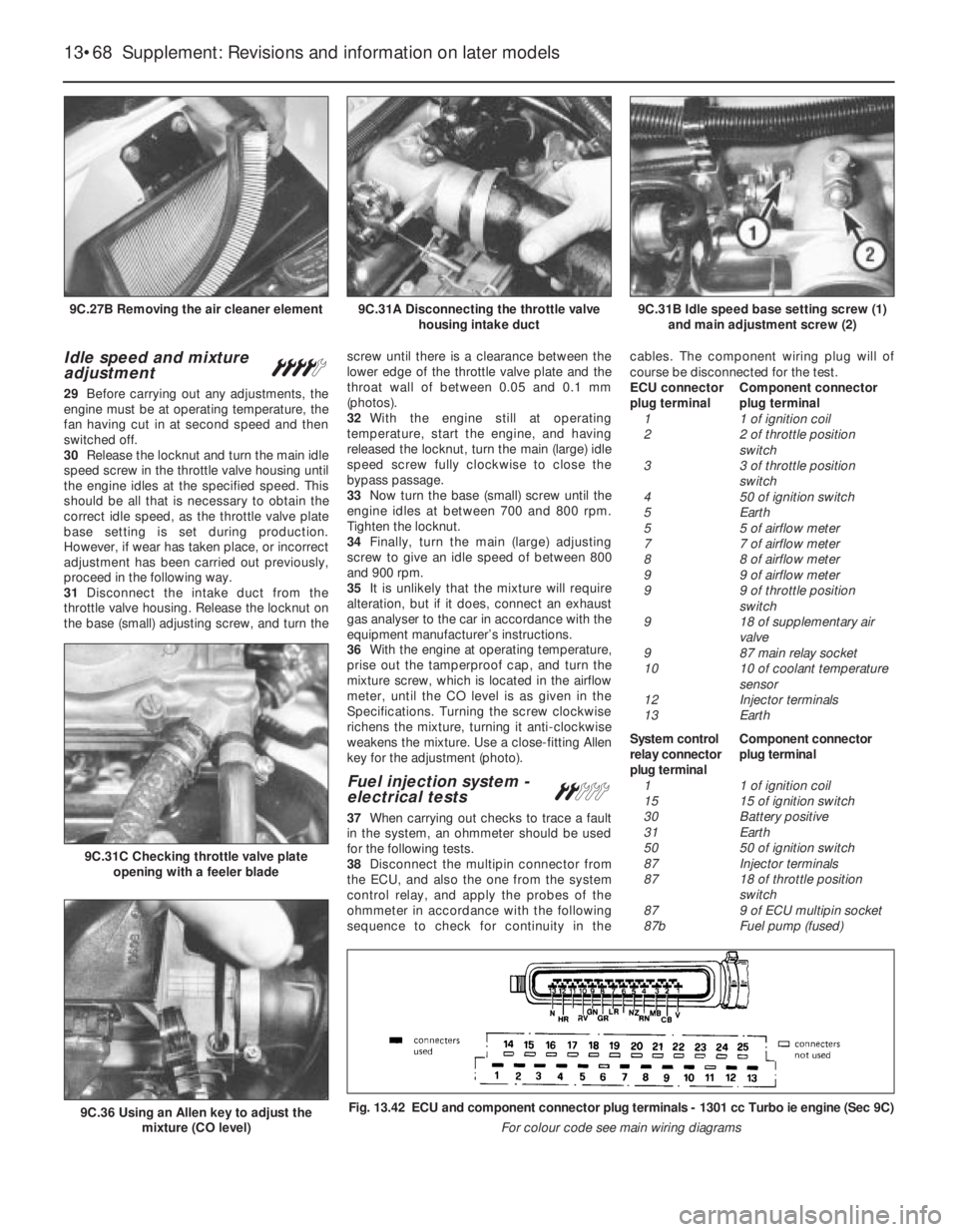
engagement with the flywheel starter ring
gear. As the solenoid reaches the end of its
stroke, and with the pinion by now partially
engaged with the flywheel ring gear, the main
fixed and moving contacts close and engage
the starter motor to rotate the engine.
3This pre-engagement of the starter drive
does much to reduce the wear on the flywheel
ring gear associated with inertia type starter
motors.
4If the starter fails, some fault-finding can be
done with it still on the car. Check the ignition
warning light comes on, and does not go out
when the starter is switched on. If it goes out,
the fault is probably in the battery. If it stays
bright, get an assistant to work the switch,whilst listening to the starter. Listen to find out
if the solenoid clicks into position. If it does
not, pull off the solenoid wire, and check it
with a test bulb. If the wire is live when the key
is turned, but the solenoid does not move,
take off the starter and remove it to the bench
for overhaul.
8 Starter motor-
removal and refitting
1
1Disconnect the battery negative lead.
2Disconnect the lead from the starter motor
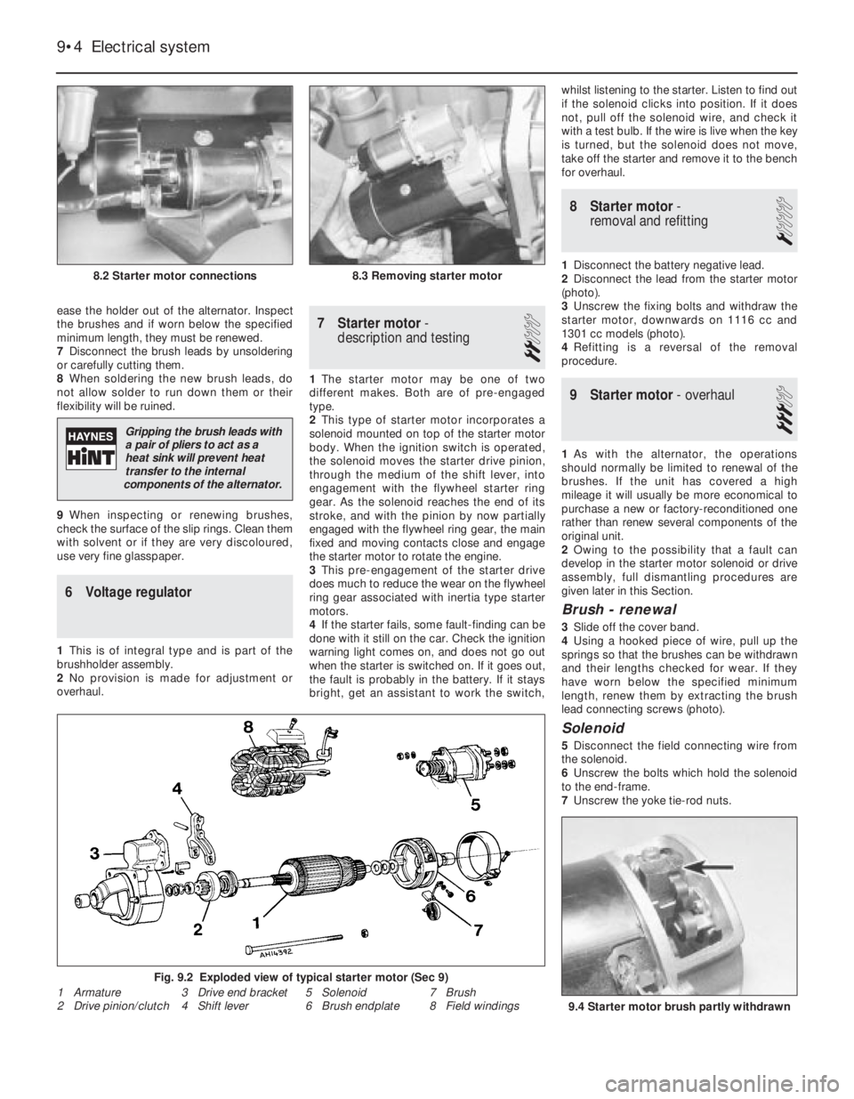
(photo).
3Unscrew the fixing bolts and withdraw the
starter motor, downwards on 1116 cc and
1301 cc models (photo).
4Refitting is a reversal of the removal
procedure.
9 Starter motor- overhaul
3
1As with the alternator, the operations
should normally be limited to renewal of the
brushes. If the unit has covered a high
mileage it will usually be more economical to
purchase a new or factory-reconditioned one
rather than renew several components of the
original unit.
2Owing to the possibility that a fault can
develop in the starter motor solenoid or drive
assembly, full dismantling procedures are
given later in this Section.
Brush - renewal
3Slide off the cover band.
4Using a hooked piece of wire, pull up the
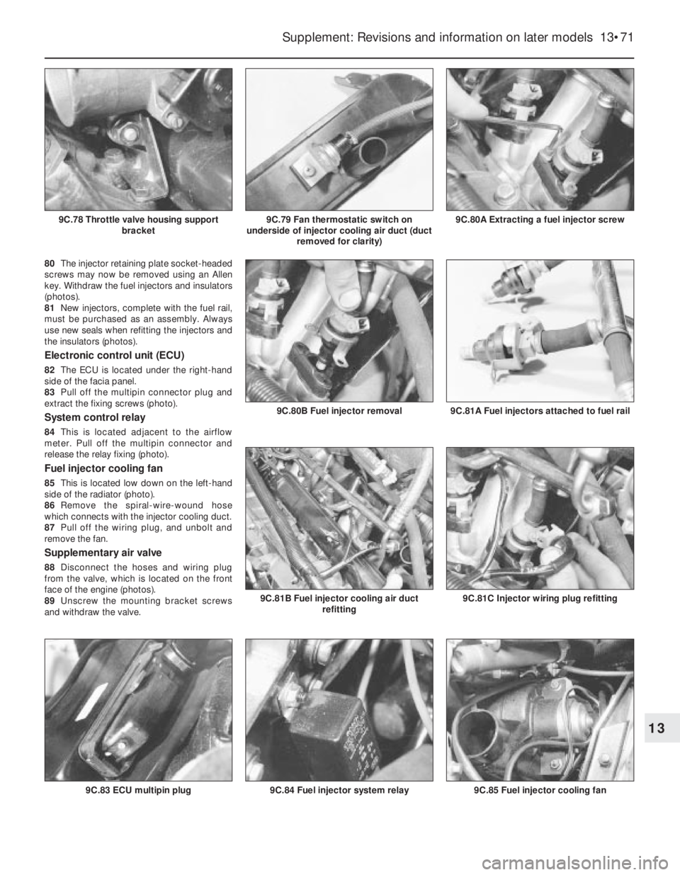
springs so that the brushes can be withdrawn
and their lengths checked for wear. If they
have worn below the specified minimum
length, renew them by extracting the brush
lead connecting screws (photo).
Solenoid
5Disconnect the field connecting wire from
the solenoid.
6Unscrew the bolts which hold the solenoid
to the end-frame.
7Unscrew the yoke tie-rod nuts.
9•4 Electrical system
9.4 Starter motor brush partly withdrawn
8.2 Starter motor connections8.3 Removing starter motor
Fig. 9.2 Exploded view of typical starter motor (Sec 9)
1 Armature
2 Drive pinion/clutch3 Drive end bracket
4 Shift lever5 Solenoid
6 Brush endplate7 Brush
8 Field windings
Gripping the brush leads with
a pair of pliers to act as a
heat sink will prevent heat
transfer to the internal
components of the alternator.
Page 100 of 303
paintwork should the drill slip. Three methods
of making the hole are in use:
a) Use a hole saw in the electric drill. This is,
in effect, a circular hacksaw blade
wrapped round a former with a centre
pilot drill.
b) Use a tank cutter which also has cutting
teeth, but is made to shear the metal by
tightening with an Allen key.
c) The hard way of drilling out the circle is
using a small drill, say 1/8 in (3 mm), so
that the holes overlap. The centre metal
drops out and the hole is finished with
round and half-round files.
14Whichever method is used, the burr is
removed from the body metal and paint
removed from the underside. The aerial is fitted
tightly ensuring that the earth fixing, usually a
serrated washer, ring or clamp, is making a
solid connection. This earth connection is
important in reducing interference. Cover any
bare metal with primer paint and topcoat, and
follow by underseal if desired.
15Aerial feeder cable routing should avoid
the engine compartment and areas where
stress might occur, eg under the carpet where
feet will be located.Loudspeakers
16A mono speaker may be located under
the facia panel beneath the glovebox.
17Provision is made for twin speakers within
the door tidy bins or under the rear shelf
mountings.
18Speakers should be matched to the
output stage of the equipment, particularly as
regards the recommended impedance. Power
transistors used for driving speakers are
sensitive to the loading placed on them.
31 Electrically-operated front
door windows
3
1The electrically-operated front door
windows are controlled by switches on the
centre console or in the door armrest
(depending on model). The regulator motor
and cable are located within the door cavity.
2To gain access to the assembly, remove
the door trim panel as described in Chap-
ter 12.
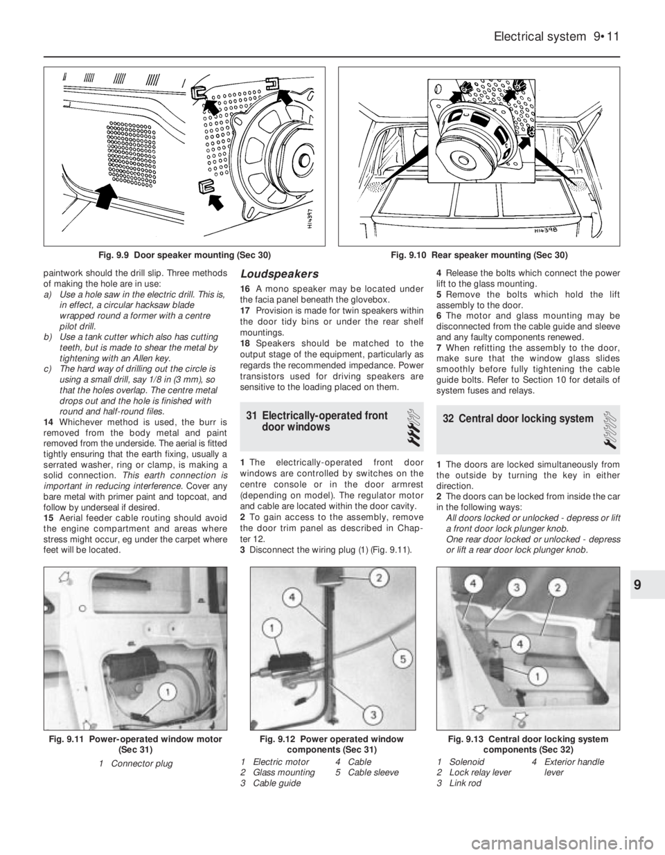
3Disconnect the wiring plug (1) (Fig. 9.11).4Release the bolts which connect the power
lift to the glass mounting.
5Remove the bolts which hold the lift
assembly to the door.
6The motor and glass mounting may be
disconnected from the cable guide and sleeve
and any faulty components renewed.
7When refitting the assembly to the door,
make sure that the window glass slides
smoothly before fully tightening the cable
guide bolts. Refer to Section 10 for details of
system fuses and relays.
32 Central door locking system
1
1The doors are locked simultaneously from
the outside by turning the key in either
direction.
2The doors can be locked from inside the car
in the following ways:
All doors locked or unlocked - depress or lift
a front door lock plunger knob.
One rear door locked or unlocked - depress
or lift a rear door lock plunger knob.
Electrical system 9•11
Fig. 9.9 Door speaker mounting (Sec 30)Fig. 9.10 Rear speaker mounting (Sec 30)
Fig. 9.13 Central door locking system
components (Sec 32)Fig. 9.12 Power operated window
components (Sec 31)Fig. 9.11 Power-operated window motor
(Sec 31)
1 Connector plug
1 Electric motor
2 Glass mounting
3 Cable guide4 Cable
5 Cable sleeve1 Solenoid
2 Lock relay lever
3 Link rod4 Exterior handle
lever
9
Page 101 of 303
3The centralised door locking system can
operate independently of the key.
4To gain access to the lock solenoid and
linkage, remove the front door trim panel as
described in Chapter 12.
5Disconnect the battery negative lead.
6Disconnect the electrical wiring plugs from
the solenoid within the door cavity.
7Disconnect the solenoid from the lock lever
by removing the clip.
8Unscrew the two bolts which secure the
solenoid to the door and remove it.
9Renew the solenoid or switch as necessary.
10Refitting is a reversal of removal.
11Refer to Section 10 for details of system
fuses and relays.
33 Economy gauge
(Econometer)
2
1This device is fitted to ES (energy saving)
models and indicates to the driver the fuel
consumption (in litres per 100 km) coupled
with a needle which moves over coloured
sections of a dial to make the driver aware
that his method of driving is either conducive
to high or low fuel consumption. Refer to
Chapter 3, Section 16.
2The device is essentially a vacuum gauge
which also incorporates a warning lamp to
indicate to the driver when a change of gear is
required.
3A fuel cut-out valve (see Chapter 3, Sec-
tion 11) is used in conjunction with the
economy gauge so that when the accelerator
pedal is released during a pre-determined
engine speed range, fuel supply to the engine
is stopped, but resumes when the engine
speed falls below the specified range.
LED (light emitter diode)
4The gearchange indicator will only light up
at engine speeds in excess of 2000 rev/min
for vacuum pressures up to 600 mm Hg in 1st,
2nd and 3rd speed gears and for vacuum
pressures up to 676 mm Hg in 4th speedgear. The light will not come on if 5th speed
gear is engaged or if the coolant temperature
is below 55ºC.
5There is a two second delay in the light
coming on to prevent it operating during rapid
acceleration in a low gear.
6If the LED light comes on during
deceleration it should be ignored.
Fault finding
7A faulty economy gauge should be checked
in the following way.
8Refer to Section 21 and remove the
instrument panel.
9Disconnect the economy gauge L
connector and then connect a test lamp
between the BN cable contact and earth. If
the lamp comes on then the gauge supply
circuit is not open. If the lamp does not come
on, check all connections in the supply cable
which comes from the interconnecting unit of
the electrical system, also Fuse No 12.
10Now connect a voltmeter between the
white cable and earth. Check the voltage with
the engine not running, but the ignition
switched on. It should be between 0.7 and
0.9 volt. If the reading varies considerably
from that specified, check the connections
between the economy gauge and the fuel
cut-out device control unit. If the fault cannot
be rectified, renew the ignition control unit
(Digiplex system, see Chapter 4).
11Now check the closed throttle valve plate
switch by connecting a voltmeter between the
brown and BN cables of the L connector. With
the valve plate open, there should be no
reading, but with it open, voltage should be
indicated.
12Failure to conform as described will be
due to a faulty earth in the switch or a faulty
fuel cut-out device control unit.
13A further test of the throttle valve plate
switch may be carried out by disconnecting
the multi-plug from the fuel cut-out device
control unit.
14Connect a test lamp to contact 4 (positive
battery terminal). The lamp should come on,
when the engine is idling or the accelerator
released. If it does not, renew the throttle
valve plate switch.15Connect a tachometer to the brown/white
cable contact in the L connector and record
the engine speed with the engine running. If
no reading is obtained, renew the Digiplex
ignition control unit which must be faulty.
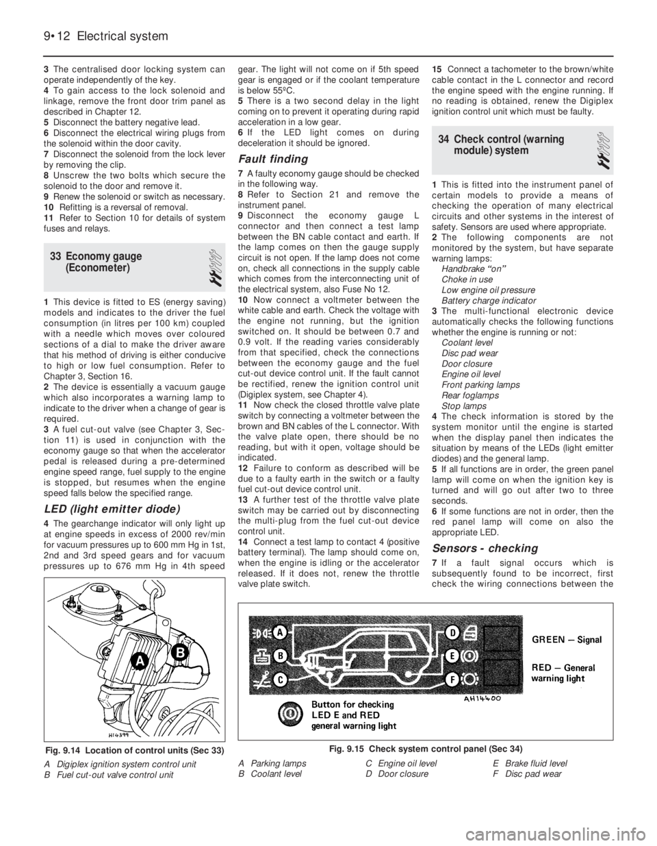
34 Check control (warning
module) system
2
1This is fitted into the instrument panel of
certain models to provide a means of
checking the operation of many electrical
circuits and other systems in the interest of
safety. Sensors are used where appropriate.
2The following components are not
monitored by the system, but have separate
warning lamps:
Handbrake “on”
Choke in use
Low engine oil pressure
Battery charge indicator
3The multi-functional electronic device
automatically checks the following functions
whether the engine is running or not:
Coolant level
Disc pad wear
Door closure
Engine oil level
Front parking lamps
Rear foglamps
Stop lamps
4The check information is stored by the
system monitor until the engine is started
when the display panel then indicates the
situation by means of the LEDs (light emitter
diodes) and the general lamp.
5If all functions are in order, the green panel
lamp will come on when the ignition key is
turned and will go out after two to three
seconds.
6If some functions are not in order, then the
red panel lamp will come on also the
appropriate LED.
Sensors - checking
7If a fault signal occurs which is
subsequently found to be incorrect, first
check the wiring connections between the
9•12 Electrical system
Fig. 9.15 Check system control panel (Sec 34)
A Parking lamps
B Coolant levelC Engine oil level
D Door closureE Brake fluid level
F Disc pad wearFig. 9.14 Location of control units (Sec 33)
A Digiplex ignition system control unit
B Fuel cut-out valve control unit
Page 115 of 303
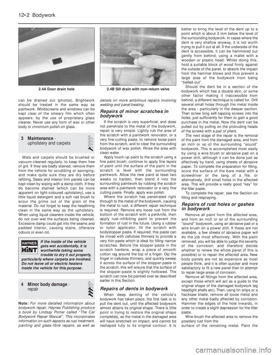
can be drained out (photos). Brightwork
should be treated in the same way as
paintwork. Windscreens and windows can be
kept clear of the smeary film which often
appears, by the use of proprietary glass
cleaner. Never use any form of wax or other
body or chromium polish on glass.
3 Maintenance-
upholstery and carpets
1
Mats and carpets should be brushed or
vacuum-cleaned regularly, to keep them free
of grit. If they are badly stained, remove them
from the vehicle for scrubbing or sponging,
and make quite sure they are dry before
refitting. Seats and interior trim panels can be
kept clean by wiping with a damp cloth. If they
do become stained (which can be more
apparent on light-coloured upholstery), use a
little liquid detergent and a soft nail brush to
scour the grime out of the grain of the
material. Do not forget to keep the headlining
clean in the same way as the upholstery.
When using liquid cleaners inside the vehicle,
do not over-wet the surfaces being cleaned.
Excessive damp could get into the seams and
padded interior, causing stains, offensive
odours or even rot.
4 Minor body damage-
repair
3
Note:For more detailed information about
bodywork repair, Haynes Publishing produce
a book by Lindsay Porter called “The Car
Bodywork Repair Manual”. This incorporates
information on such aspects as rust treatment,
painting and glass-fibre repairs, as well asdetails on more ambitious repairs involving
welding and panel beating.
Repairs of minor scratches in
bodywork
If the scratch is very superficial, and does
not penetrate to the metal of the bodywork,
repair is very simple. Lightly rub the area of
the scratch with a paintwork renovator, or a
very fine cutting paste, to remove loose paint
from the scratch, and to clear the surrounding
bodywork of wax polish. Rinse the area with
clean water.
Apply touch-up paint to the scratch using a
fine paint brush; continue to apply fine layers
of paint until the surface of the paint in the
scratch is level with the surrounding
paintwork. Allow the new paint at least two
weeks to harden, then blend it into the
surrounding paintwork by rubbing the scratch
area with a paintwork renovator or a very fine
cutting paste. Finally, apply wax polish.
Where the scratch has penetrated right
through to the metal of the bodywork, causing
the metal to rust, a different repair technique
is required. Remove any loose rust from the
bottom of the scratch with a penknife, then
apply rust-inhibiting paint to prevent the
formation of rust in the future. Using a rubber
or nylon applicator, fill the scratch with
bodystopper paste. If required, this paste can
be mixed with cellulose thinners to provide a
very thin paste which is ideal for filling narrow
scratches. Before the stopper-paste in the
scratch hardens, wrap a piece of smooth
cotton rag around the top of a finger. Dip the
finger in cellulose thinners, and quickly sweep
it across the surface of the stopper-paste in
the scratch; this will ensure that the surface of
the stopper-paste is slightly hollowed. The
scratch can now be painted over as described
earlier in this Section.
Repairs of dents in bodywork
When deep denting of the vehicle’s
bodywork has taken place, the first task is to
pull the dent out, until the affected bodywork
almost attains its original shape. There is little
point in trying to restore the original shape
completely, as the metal in the damaged area
will have stretched on impact, and cannot be
reshaped fully to its original contour. It isbetter to bring the level of the dent up to a
point which is about 3 mm below the level of
the surrounding bodywork. In cases where the
dent is very shallow anyway, it is not worth
trying to pull it out at all. If the underside of the
dent is accessible, it can be hammered out
gently from behind, using a mallet with a
wooden or plastic head. Whilst doing this,
hold a suitable block of wood firmly against
the outside of the panel, to absorb the impact
from the hammer blows and thus prevent a
large area of the bodywork from being
“belled-out”.
Should the dent be in a section of the
bodywork which has a double skin, or some
other factor making it inaccessible from
behind, a different technique is called for. Drill
several small holes through the metal inside
the area - particularly in the deeper section.
Then screw long self-tapping screws into the
holes, just sufficiently for them to gain a good
purchase in the metal. Now the dent can be
pulled out by pulling on the protruding heads
of the screws with a pair of pliers.
The next stage of the repair is the removal
of the paint from the damaged area, and from
an inch or so of the surrounding “sound”
bodywork. This is accomplished most easily
by using a wire brush or abrasive pad on a
power drill, although it can be done just as
effectively by hand, using sheets of abrasive
paper. To complete the preparation for filling,
score the surface of the bare metal with a
screwdriver or the tang of a file, or
alternatively, drill small holes in the affected
area. This will provide a really good “key” for
the filler paste.
To complete the repair, see the Section on
filling and respraying.
Repairs of rust holes or gashes
in bodywork
Remove all paint from the affected area,
and from an inch or so of the surrounding
“sound” bodywork, using an abrasive pad or a
wire brush on a power drill. If these are not
available, a few sheets of abrasive paper will
do the job most effectively. With the paint
removed, you will be able to judge the severity
of the corrosion, and therefore decide
whether to renew the whole panel (if this is
possible) or to repair the affected area. New
body panels are not as expensive as most
people think, and it is often quicker and more
satisfactory to fit a new panel than to attempt
to repair large areas of corrosion.
Remove all fittings from the affected area,
except those which will act as a guide to the
original shape of the damaged bodywork (eg
headlight shells etc). Then, using tin snips or a
hacksaw blade, remove all loose metal and
any other metal badly affected by corrosion.
Hammer the edges of the hole inwards, in
order to create a slight depression for the filler
paste.
Wire-brush the affected area to remove the
powdery rust from the
surface of the remaining metal. Paint the
12•2 Bodywork
2.4B Sill drain with non-return valve2.4A Door drain hole
If the inside of the vehicle
gets wet accidentally, it is
worthwhile taking some
trouble to dry it out properly,
particularly where carpets are involved.
Do not leave oil or electric heaters
inside the vehicle for this purpose.
Page 147 of 303
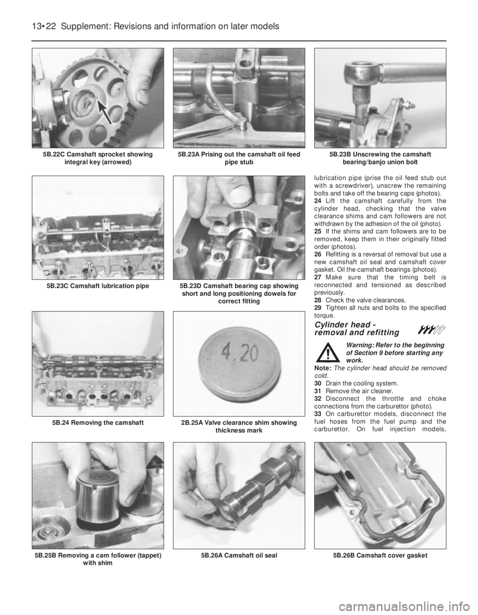
lubrication pipe (prise the oil feed stub out
with a screwdriver), unscrew the remaining
bolts and take off the bearing caps (photos).
24Lift the camshaft carefully from the
cylinder head, checking that the valve
clearance shims and cam followers are not
withdrawn by the adhesion of the oil (photo).
25If the shims and cam followers are to be
removed, keep them in their originally fitted
order (photos).
26Refitting is a reversal of removal but use a
new camshaft oil seal and camshaft cover
gasket. Oil the camshaft bearings (photos).
27Make sure that the timing belt is
reconnected and tensioned as described
previously.
28Check the valve clearances.
29Tighten all nuts and bolts to the specified
torque.
Cylinder head -
removal and refitting#
Warning: Refer to the beginning
of Section 9 before starting any
work.
Note: The cylinder head should be removed
cold.
30Drain the cooling system.
31Remove the air cleaner.
32Disconnect the throttle and choke
connections from the carburettor (photo).
33On carburettor models, disconnect the
fuel hoses from the fuel pump and the
carburettor. On fuel injection models,
13•22 Supplement: Revisions and information on later models
5B.26B Camshaft cover gasket5B.26A Camshaft oil seal5B.25B Removing a cam follower (tappet)
with shim
2B.25A Valve clearance shim showing
thickness mark5B.24 Removing the camshaft
5B.23D Camshaft bearing cap showing
short and long positioning dowels for
correct fitting5B.23C Camshaft lubrication pipe
5B.23B Unscrewing the camshaft
bearing/banjo union bolt5B.23A Prising out the camshaft oil feed
pipe stub5B.22C Camshaft sprocket showing
integral key (arrowed)
Page 157 of 303
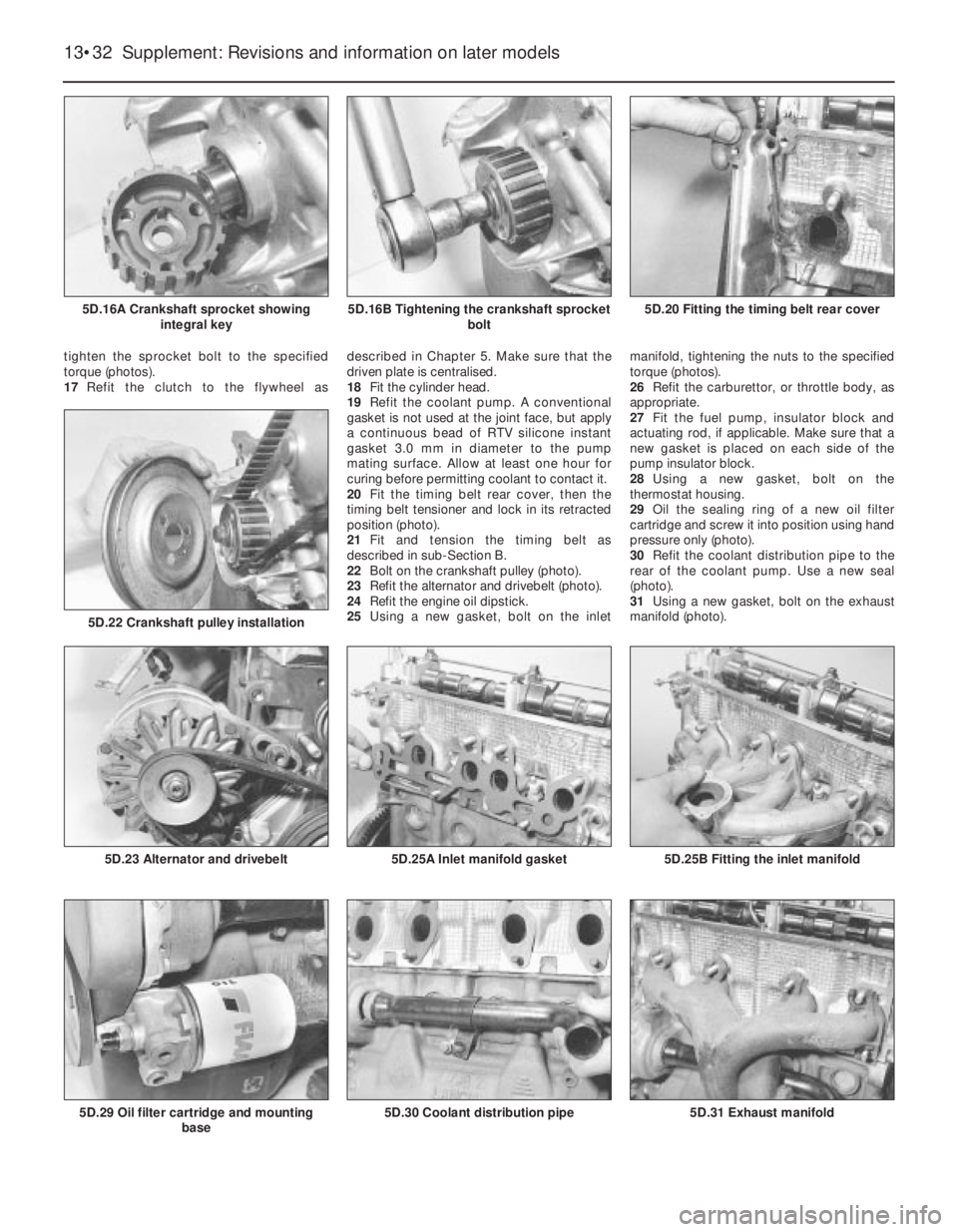
tighten the sprocket bolt to the specified
torque (photos).
17Refit the clutch to the flywheel asdescribed in Chapter 5. Make sure that the
driven plate is centralised.
18Fit the cylinder head.
19Refit the coolant pump. A conventional
gasket is not used at the joint face, but apply
a continuous bead of RTV silicone instant
gasket 3.0 mm in diameter to the pump
mating surface. Allow at least one hour for
curing before permitting coolant to contact it.
20Fit the timing belt rear cover, then the
timing belt tensioner and lock in its retracted
position (photo).
21Fit and tension the timing belt as
described in sub-Section B.
22Bolt on the crankshaft pulley (photo).
23Refit the alternator and drivebelt (photo).
24Refit the engine oil dipstick.
25Using a new gasket, bolt on the inletmanifold, tightening the nuts to the specified
torque (photos).
26Refit the carburettor, or throttle body, as
appropriate.
27Fit the fuel pump, insulator block and
actuating rod, if applicable. Make sure that a
new gasket is placed on each side of the
pump insulator block.
28Using a new gasket, bolt on the
thermostat housing.
29Oil the sealing ring of a new oil filter
cartridge and screw it into position using hand
pressure only (photo).
30Refit the coolant distribution pipe to the
rear of the coolant pump. Use a new seal
(photo).
31Using a new gasket, bolt on the exhaust
manifold (photo).
13•32 Supplement: Revisions and information on later models
5D.31 Exhaust manifold5D.30 Coolant distribution pipe5D.29 Oil filter cartridge and mounting
base
5D.25B Fitting the inlet manifold5D.25A Inlet manifold gasket5D.23 Alternator and drivebelt
5D.22 Crankshaft pulley installation
5D.20 Fitting the timing belt rear cover5D.16B Tightening the crankshaft sprocket
bolt5D.16A Crankshaft sprocket showing
integral key
Page 165 of 303
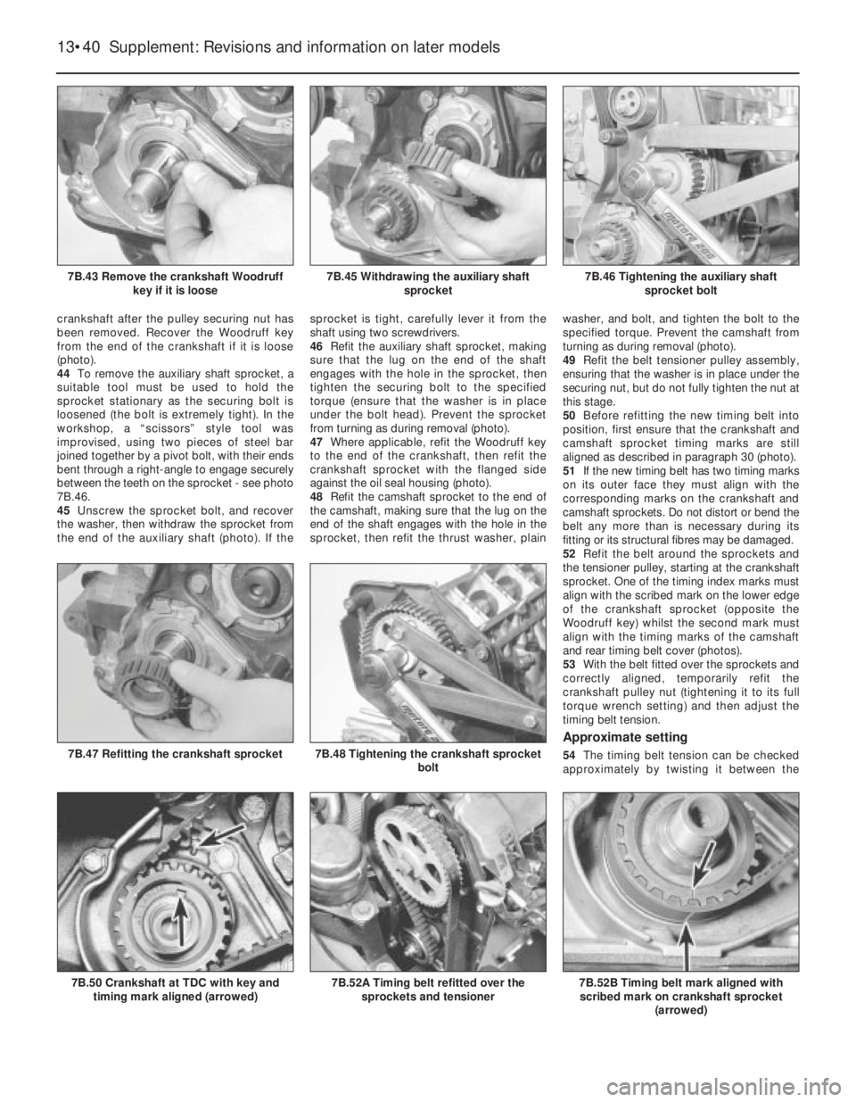
crankshaft after the pulley securing nut has
been removed. Recover the Woodruff key
from the end of the crankshaft if it is loose
(photo).
44To remove the auxiliary shaft sprocket, a
suitable tool must be used to hold the
sprocket stationary as the securing bolt is
loosened (the bolt is extremely tight). In the
workshop, a “scissors” style tool was
improvised, using two pieces of steel bar
joined together by a pivot bolt, with their ends
bent through a right-angle to engage securely
between the teeth on the sprocket - see photo
7B.46.
45Unscrew the sprocket bolt, and recover
the washer, then withdraw the sprocket from
the end of the auxiliary shaft (photo). If thesprocket is tight, carefully lever it from the
shaft using two screwdrivers.
46Refit the auxiliary shaft sprocket, making
sure that the lug on the end of the shaft
engages with the hole in the sprocket, then
tighten the securing bolt to the specified
torque (ensure that the washer is in place
under the bolt head). Prevent the sprocket
from turning as during removal (photo).
47Where applicable, refit the Woodruff key
to the end of the crankshaft, then refit the
crankshaft sprocket with the flanged side
against the oil seal housing (photo).
48Refit the camshaft sprocket to the end of
the camshaft, making sure that the lug on the
end of the shaft engages with the hole in the
sprocket, then refit the thrust washer, plainwasher, and bolt, and tighten the bolt to the
specified torque. Prevent the camshaft from
turning as during removal (photo).
49Refit the belt tensioner pulley assembly,
ensuring that the washer is in place under the
securing nut, but do not fully tighten the nut at
this stage.
50Before refitting the new timing belt into
position, first ensure that the crankshaft and
camshaft sprocket timing marks are still
aligned as described in paragraph 30 (photo).
51If the new timing belt has two timing marks
on its outer face they must align with the
corresponding marks on the crankshaft and
camshaft sprockets. Do not distort or bend the
belt any more than is necessary during its
fitting or its structural fibres may be damaged.
52Refit the belt around the sprockets and
the tensioner pulley, starting at the crankshaft
sprocket. One of the timing index marks must
align with the scribed mark on the lower edge
of the crankshaft sprocket (opposite the
Woodruff key) whilst the second mark must
align with the timing marks of the camshaft
and rear timing belt cover (photos).
53With the belt fitted over the sprockets and
correctly aligned, temporarily refit the
crankshaft pulley nut (tightening it to its full
torque wrench setting) and then adjust the
timing belt tension.
Approximate setting
54The timing belt tension can be checked
approximately by twisting it between the
13•40 Supplement: Revisions and information on later models
7B.52B Timing belt mark aligned with
scribed mark on crankshaft sprocket
(arrowed)7B.52A Timing belt refitted over the
sprockets and tensioner7B.50 Crankshaft at TDC with key and
timing mark aligned (arrowed)
7B.48 Tightening the crankshaft sprocket
bolt7B.47 Refitting the crankshaft sprocket
7B.46 Tightening the auxiliary shaft
sprocket bolt7B.45 Withdrawing the auxiliary shaft
sprocket7B.43 Remove the crankshaft Woodruff
key if it is loose
Page 191 of 303
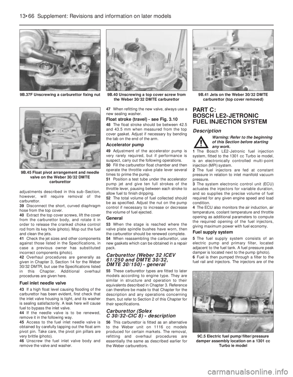
adjustments described in this sub-Section,
however, will require removal of the
carburettor.
39Disconnect the short, curved diaphragm
hose from the top cover.
40Extract the top cover screws, lift the cover
from the carburettor body, and rotate it in
order to release the cranked choke control
rod from its key hole (photo). Mop out the fuel
and clean the jets.
41Check the jet sizes and other components
against those listed in the Specifications, in
case a previous owner has substituted
incorrect components (photo).
42Overhaul procedures are generally as
given in Chapter 3, Section 14 for the Weber
30/32 DMTR, but use the Specifications listed
in this Chapter. Additional overhaul
procedures are given here.
Fuel inlet needle valve
43If a high float level causing flooding of the
carburettor has been evident, first check that
the inlet valve housing is tight, and its washer
is sealing satisfactorily. A leak here will cause
fuel to bypass the inlet valve.
44If the needle valve is to be renewed,
remove it in the following way.
45Access to the fuel inlet needle valve is
obtained by carefully tapping out the float arm
pivot pin. Take care, the pivot pin pillars are
very brittle (photo).
46Unscrew the fuel inlet valve body and
remove the valve and washer.47When refitting the new valve, always use a
new sealing washer.
Float stroke (travel) - see Fig. 3.10
48The float stroke should be between 42.5
and 43.5 mm when measured from the top
cover gasket. Adjust if necessary by bending
the tab on the end of the arm.
Accelerator pump
49Adjustment of the accelerator pump is
very rarely required, but if performance is
suspect, carry out the following operations.
50Fill the carburettor float chamber and then
operate the throttle valve plate lever several
times to prime the pump.
51Position a test tube under the accelerator
pump jet and give ten full strokes of the
throttle lever, pausing between each stroke to
allow fuel to finish dripping.
52The total volume of fuel collected should
be as specified. Adjust the nut on the pump
control if necessary to increase or decrease
the volume of fuel ejected.
General
53When the stage is reached where the
valve plate spindle bushes have worn, then
the carburettor should be renewed complete.
54When reassembling the carburettor, use
new gaskets which can be obtained in a repair
pack.
Carburettor (Weber 32 ICEV
61/250 and DMTE 30/32,
DMTE 30/150) - general
55These carburettor types are fitted to later
models according to engine type. They are
similar in structure and operation to their
equivalents described in Chapter 3. Reference
can therefore be made to that Chapter for the
description and any operations concerning
them, but refer to Section 2 of this Chapter for
their specifications.
Carburettor (Solex
C 30/32-CIC 8) - description
56This carburettor is fitted as an alternative
to the Weber unit on 1116 cc models
produced for certain markets. The removal,
refitting and overhaul procedures are
essentially the same as described earlier for
the Weber carburettors.
PART C:
BOSCH LE2-JETRONIC
FUEL INJECTION SYSTEM
Description
Warning: Refer to the beginning
of this Section before starting
any work.
1The Bosch LE2-Jetronic fuel injection
system, fitted to the 1301 cc Turbo ie model,
is an electronically controlled multi-point
injection (MPi) system.
2The fuel injectors are fed at constant
pressure in relation to inlet manifold vacuum
pressure.
3The system electronic control unit (ECU)
actuates the injectors for variable duration,
and so supplies the precise volume of fuel
required for any given engine speed and load
condition.
4The ECU also monitors the air induction, air
temperature, coolant temperature and throttle
opening as additional parameters to compute
the required opening of the fuel injectors,
giving maximum power with fuel economy.
Fuel supply system
5The fuel supply system consists of an
electric pump and primary filter, located
adjacent to the fuel tank. A fuel pressure peak
damper is located next to the pump (photo).
6Fuel is then pumped through a filter to the
fuel rail and injectors. The injectors are of the
13•66 Supplement: Revisions and information on later models
9C.5 Electric fuel pump/filter/pressure
damper assembly location on a 1301 cc
Turbo ie model
9B.41 Jets on the Weber 30/32 DMTE
carburettor (top cover removed)
9B.45 Float pivot arrangement and needle
valve on the Weber 30/32 DMTE
carburettor
9B.40 Unscrewing a top cover screw from
the Weber 30/32 DMTE carburettor9B.37F Unscrewing a carburettor fixing nut
Page 193 of 303
Idle speed and mixture
adjustment¢
29Before carrying out any adjustments, the
engine must be at operating temperature, the
fan having cut in at second speed and then
switched off.
30Release the locknut and turn the main idle
speed screw in the throttle valve housing until
the engine idles at the specified speed. This
should be all that is necessary to obtain the
correct idle speed, as the throttle valve plate
base setting is set during production.
However, if wear has taken place, or incorrect
adjustment has been carried out previously,
proceed in the following way.
31Disconnect the intake duct from the
throttle valve housing. Release the locknut on
the base (small) adjusting screw, and turn thescrew until there is a clearance between the
lower edge of the throttle valve plate and the
throat wall of between 0.05 and 0.1 mm
(photos).
32With the engine still at operating
temperature, start the engine, and having
released the locknut, turn the main (large) idle
speed screw fully clockwise to close the
bypass passage.
33Now turn the base (small) screw until the
engine idles at between 700 and 800 rpm.
Tighten the locknut.
34Finally, turn the main (large) adjusting
screw to give an idle speed of between 800
and 900 rpm.
35It is unlikely that the mixture will require
alteration, but if it does, connect an exhaust
gas analyser to the car in accordance with the
equipment manufacturer’s instructions.
36With the engine at operating temperature,
prise out the tamperproof cap, and turn the
mixture screw, which is located in the airflow
meter, until the CO level is as given in the
Specifications. Turning the screw clockwise
richens the mixture, turning it anti-clockwise
weakens the mixture. Use a close-fitting Allen
key for the adjustment (photo).
Fuel injection system -
electrical testsª
37When carrying out checks to trace a fault
in the system, an ohmmeter should be used
for the following tests.
38Disconnect the multipin connector from
the ECU, and also the one from the system
control relay, and apply the probes of the
ohmmeter in accordance with the following
sequence to check for continuity in thecables. The component wiring plug will of
course be disconnected for the test.
ECU connector Component connector
plug terminal plug terminal
1 1 of ignition coil
2 2 of throttle position
switch
3 3 of throttle position
switch
4 50 of ignition switch
5 Earth
5 5 of airflow meter
7 7 of airflow meter
8 8 of airflow meter
9 9 of airflow meter
9 9 of throttle position
switch
9 18 of supplementary air
valve
9 87 main relay socket
10 10 of coolant temperature
sensor
12 Injector terminals
13 Earth
System control Component connector
relay connector plug terminal
plug terminal
1 1 of ignition coil
15 15 of ignition switch
30 Battery positive
31 Earth
50 50 of ignition switch
87 Injector terminals
87 18 of throttle position
switch
87 9 of ECU multipin socket
87b Fuel pump (fused)
13•68 Supplement: Revisions and information on later models
Fig. 13.42 ECU and component connector plug terminals - 1301 cc Turbo ie engine (Sec 9C)
For colour code see main wiring diagrams
9C.31C Checking throttle valve plate
opening with a feeler blade
9C.36 Using an Allen key to adjust the
mixture (CO level)
9C.31B Idle speed base setting screw (1)
and main adjustment screw (2)9C.31A Disconnecting the throttle valve
housing intake duct9C.27B Removing the air cleaner element
Page 196 of 303
80The injector retaining plate socket-headed
screws may now be removed using an Allen
key. Withdraw the fuel injectors and insulators
(photos).
81New injectors, complete with the fuel rail,
must be purchased as an assembly. Always
use new seals when refitting the injectors and
the insulators (photos).
Electronic control unit (ECU)
82The ECU is located under the right-hand
side of the facia panel.
83Pull off the multipin connector plug and
extract the fixing screws (photo).
System control relay
84This is located adjacent to the airflow
meter. Pull off the multipin connector and
release the relay fixing (photo).
Fuel injector cooling fan
85This is located low down on the left-hand
side of the radiator (photo).
86Remove the spiral-wire-wound hose
which connects with the injector cooling duct.
87Pull off the wiring plug, and unbolt and
remove the fan.
Supplementary air valve
88Disconnect the hoses and wiring plug
from the valve, which is located on the front
face of the engine (photos).
89Unscrew the mounting bracket screws
and withdraw the valve.
Supplement: Revisions and information on later models 13•71
9C.80A Extracting a fuel injector screw9C.79 Fan thermostatic switch on
underside of injector cooling air duct (duct
removed for clarity)
9C.85 Fuel injector cooling fan9C.84 Fuel injector system relay9C.83 ECU multipin plug
9C.81C Injector wiring plug refitting9C.81B Fuel injector cooling air duct
refitting
9C.81A Fuel injectors attached to fuel rail9C.80B Fuel injector removal
13
9C.78 Throttle valve housing support
bracket