air bleeding FIAT UNO 1983 Service Repair Manual
[x] Cancel search | Manufacturer: FIAT, Model Year: 1983, Model line: UNO, Model: FIAT UNO 1983Pages: 303, PDF Size: 10.36 MB
Page 81 of 303
8
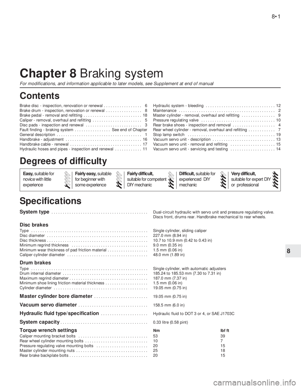
System type . . . . . . . . . . . . . . . . . . . . . . . . . . . . . . . . . . . . . . . . . . . Dual-circuit hydraulic with servo unit and pressure regulating valve.
Discs front, drums rear. Handbrake mechanical to rear wheels.
Disc brakes
Type . . . . . . . . . . . . . . . . . . . . . . . . . . . . . . . . . . . . . . . . . . . . . . . . . . . . Single cylinder, sliding caliper
Disc diameter . . . . . . . . . . . . . . . . . . . . . . . . . . . . . . . . . . . . . . . . . . . . . 227.0 mm (8.94 in)
Disc thickness . . . . . . . . . . . . . . . . . . . . . . . . . . . . . . . . . . . . . . . . . . . . . 10.7 to 10.9 mm (0.42 to 0.43 in)
Minimum regrind thickness . . . . . . . . . . . . . . . . . . . . . . . . . . . . . . . . . . 9.0 mm (0.35 in)
Minimum wear thickness of pad friction material . . . . . . . . . . . . . . . . . . 1.5 mm (0.06 in)
Caliper cylinder diameter . . . . . . . . . . . . . . . . . . . . . . . . . . . . . . . . . . . . 48.0 mm (1.89 in)
Drum brakes
Type . . . . . . . . . . . . . . . . . . . . . . . . . . . . . . . . . . . . . . . . . . . . . . . . . . . . Single cylinder, with automatic adjusters
Drum internal diameter . . . . . . . . . . . . . . . . . . . . . . . . . . . . . . . . . . . . . . 185.24 to 185.53 mm (7.30 to 7.31 in)
Maximum regrind diameter . . . . . . . . . . . . . . . . . . . . . . . . . . . . . . . . . . . 187.0 mm (7.37 in)
Minimum shoe lining friction material thickness . . . . . . . . . . . . . . . . . . . 1.5 mm (0.06 in)
Cylinder diameter . . . . . . . . . . . . . . . . . . . . . . . . . . . . . . . . . . . . . . . . . . 19.05 mm (0.75 in)
Master cylinder bore diameter . . . . . . . . . . . . . . . . . . . . . . . . 19.05 mm (0.75 in)
Vacuum servo diameter . . . . . . . . . . . . . . . . . . . . . . . . . . . . . . . 158.5 mm (6.0 in)
Hydraulic fluid type/specification . . . . . . . . . . . . . . . . . . . . . Hydraulic fluid to DOT 3 or 4, or SAE J1703C
System capacity . . . . . . . . . . . . . . . . . . . . . . . . . . . . . . . . . . . . . . . 0.33 litre (0.58 pint)
Torque wrench settingsNm lbf ft
Caliper mounting bracket bolts . . . . . . . . . . . . . . . . . . . . . . . . . . . . . . . 53 39
Rear wheel cylinder mounting bolts . . . . . . . . . . . . . . . . . . . . . . . . . . . . 10 7
Pressure regulating valve mounting bolts . . . . . . . . . . . . . . . . . . . . . . . 20 15
Master cylinder mounting nuts . . . . . . . . . . . . . . . . . . . . . . . . . . . . . . . . 25 18
Rear brake backplate bolts . . . . . . . . . . . . . . . . . . . . . . . . . . . . . . . . . . . 20 15
Chapter 8 Braking system
For modifications, and information applicable to later models, see Supplement at end of manual
Brake disc - inspection, renovation or renewal . . . . . . . . . . . . . . . . . 6
Brake drum - inspection, renovation or renewal . . . . . . . . . . . . . . . . 8
Brake pedal - removal and refitting . . . . . . . . . . . . . . . . . . . . . . . . . . 18
Caliper - removal, overhaul and refitting . . . . . . . . . . . . . . . . . . . . . . 5
Disc pads - inspection and renewal . . . . . . . . . . . . . . . . . . . . . . . . . 3
Fault finding - braking system . . . . . . . . . . . . . . . . See end of Chapter
General description . . . . . . . . . . . . . . . . . . . . . . . . . . . . . . . . . . . . . . 1
Handbrake - adjustment . . . . . . . . . . . . . . . . . . . . . . . . . . . . . . . . . . 16
Handbrake cable - renewal . . . . . . . . . . . . . . . . . . . . . . . . . . . . . . . . 17
Hydraulic hoses and pipes - inspection and renewal . . . . . . . . . . . . 11Hydraulic system - bleeding . . . . . . . . . . . . . . . . . . . . . . . . . . . . . . . 12
Maintenance . . . . . . . . . . . . . . . . . . . . . . . . . . . . . . . . . . . . . . . . . . . 2
Master cylinder - removal, overhaul and refitting . . . . . . . . . . . . . . . 9
Pressure regulating valve . . . . . . . . . . . . . . . . . . . . . . . . . . . . . . . . . 10
Rear brake shoes - inspection and removal . . . . . . . . . . . . . . . . . . . 4
Rear wheel cylinder - removal, overhaul and refitting . . . . . . . . . . . . 7
Stop lamp switch . . . . . . . . . . . . . . . . . . . . . . . . . . . . . . . . . . . . . . . 19
Vacuum servo unit - description . . . . . . . . . . . . . . . . . . . . . . . . . . . . 13
Vacuum servo unit - removal and refitting . . . . . . . . . . . . . . . . . . . . 15
Vacuum servo unit - servicing and testing . . . . . . . . . . . . . . . . . . . . 14
8•1
Specifications Contents
Easy,suitable for
novice with little
experienceFairly easy,suitable
for beginner with
some experienceFairly difficult,
suitable for competent
DIY mechanic
Difficult,suitable for
experienced DIY
mechanicVery difficult,
suitable for expert DIY
or professional
Degrees of difficulty
54321
Page 86 of 303
their originally fitted sequence and note in
which direction the seal lips are located.
11Inspect the surfaces of the piston and
cylinder bore. If scoring, corrosion or
metal-to-metal rubbing areas are evident,
renew the master cylinder complete.
12If the components are in good condition,
discard the oil seals and manipulate the new
ones into position, using the fingers only.
13Refit by reversing the removal operations;
apply pressure to the piston ends so that the
stop bolts can be fitted, then tighten the end
plug. Make sure that the grooves in the
pistons engage in the stop bolts.
14Before refitting the master cylinder to the
servo, measure the projection of the servo
piston pushrod. When the master cylinder is
fitted, there must be a clearance (see A in
Fig. 8.7) between the end of the pushrod and
the primary piston end face of between 0.825
and 1.025 mm (0.03 and 0.04 in). A depth
gauge will be required for these
measurements, the reference point being the
mating surfaces of the master cylinder and the
vacuum servo.
15Alter the adjusting screw on the servo as
necessary and lock it by applying locking fluid
to the threads on completion.16Bolt the master cylinder to the vacuum
servo or bulkhead, then reconnect the
pipelines and reservoir cap leads.
17Bleed the complete hydraulic system, as
described in Section 12.
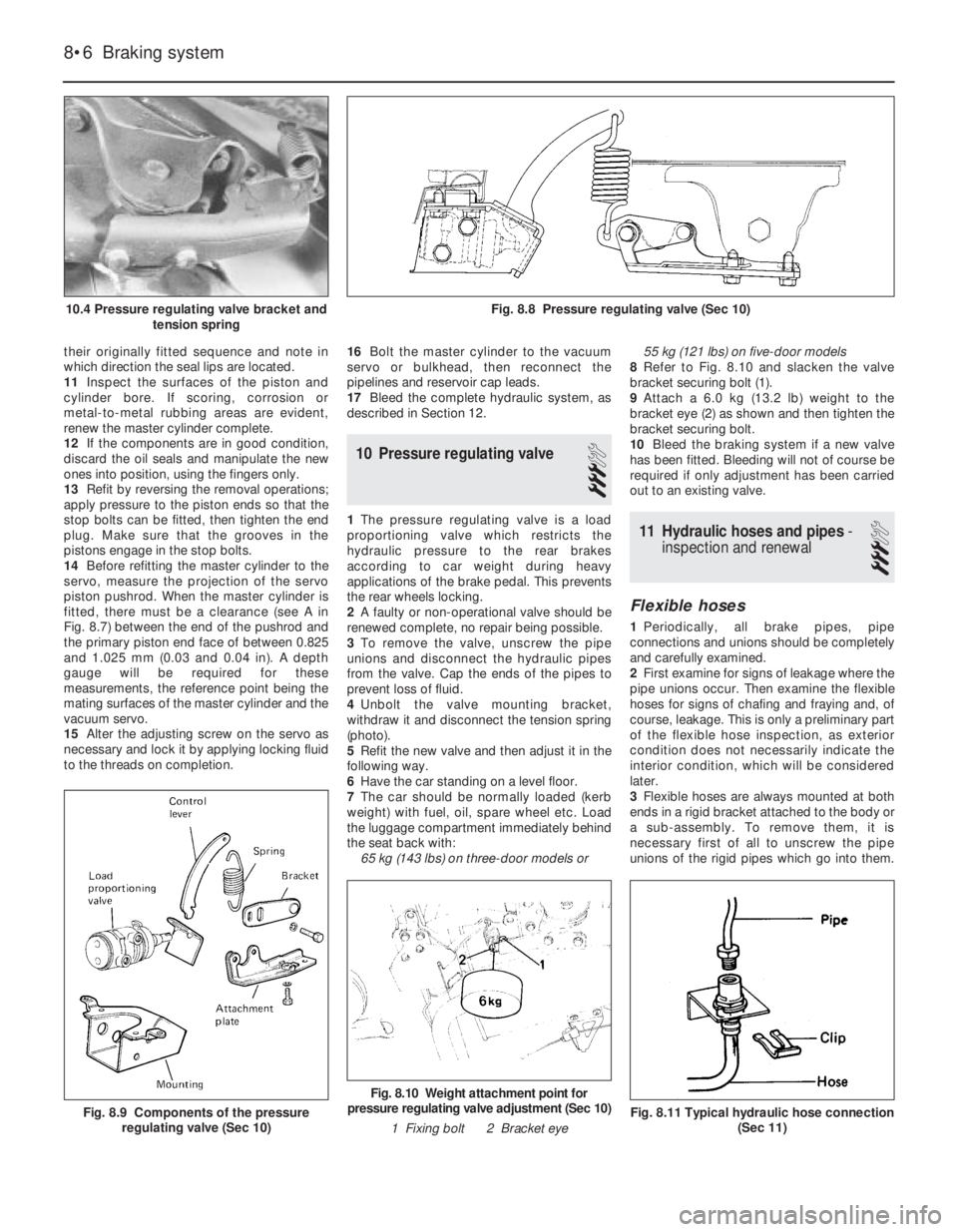
10 Pressure regulating valve
3
1The pressure regulating valve is a load
proportioning valve which restricts the
hydraulic pressure to the rear brakes
according to car weight during heavy
applications of the brake pedal. This prevents
the rear wheels locking.
2A faulty or non-operational valve should be
renewed complete, no repair being possible.
3To remove the valve, unscrew the pipe
unions and disconnect the hydraulic pipes
from the valve. Cap the ends of the pipes to
prevent loss of fluid.
4Unbolt the valve mounting bracket,
withdraw it and disconnect the tension spring
(photo).
5Refit the new valve and then adjust it in the
following way.
6Have the car standing on a level floor.
7The car should be normally loaded (kerb
weight) with fuel, oil, spare wheel etc. Load
the luggage compartment immediately behind
the seat back with:
65 kg (143 lbs) on three-door models or 55 kg (121 lbs) on five-door models
8Refer to Fig. 8.10 and slacken the valve
bracket securing bolt (1).
9Attach a 6.0 kg (13.2 lb) weight to the
bracket eye (2) as shown and then tighten the
bracket securing bolt.
10Bleed the braking system if a new valve
has been fitted. Bleeding will not of course be
required if only adjustment has been carried
out to an existing valve.11 Hydraulic hoses and pipes-
inspection and renewal
3
Flexible hoses
1Periodically, all brake pipes, pipe
connections and unions should be completely
and carefully examined.
2First examine for signs of leakage where the
pipe unions occur. Then examine the flexible
hoses for signs of chafing and fraying and, of
course, leakage. This is only a preliminary part
of the flexible hose inspection, as exterior
condition does not necessarily indicate the
interior condition, which will be considered
later.
3Flexible hoses are always mounted at both
ends in a rigid bracket attached to the body or
a sub-assembly. To remove them, it is
necessary first of all to unscrew the pipe
unions of the rigid pipes which go into them.
8•6 Braking system
Fig. 8.11 Typical hydraulic hose connection
(Sec 11)
Fig. 8.10 Weight attachment point for
pressure regulating valve adjustment (Sec 10)
1 Fixing bolt 2 Bracket eye
Fig. 8.9 Components of the pressure
regulating valve (Sec 10)
Fig. 8.8 Pressure regulating valve (Sec 10)10.4 Pressure regulating valve bracket and
tension spring
Page 87 of 303
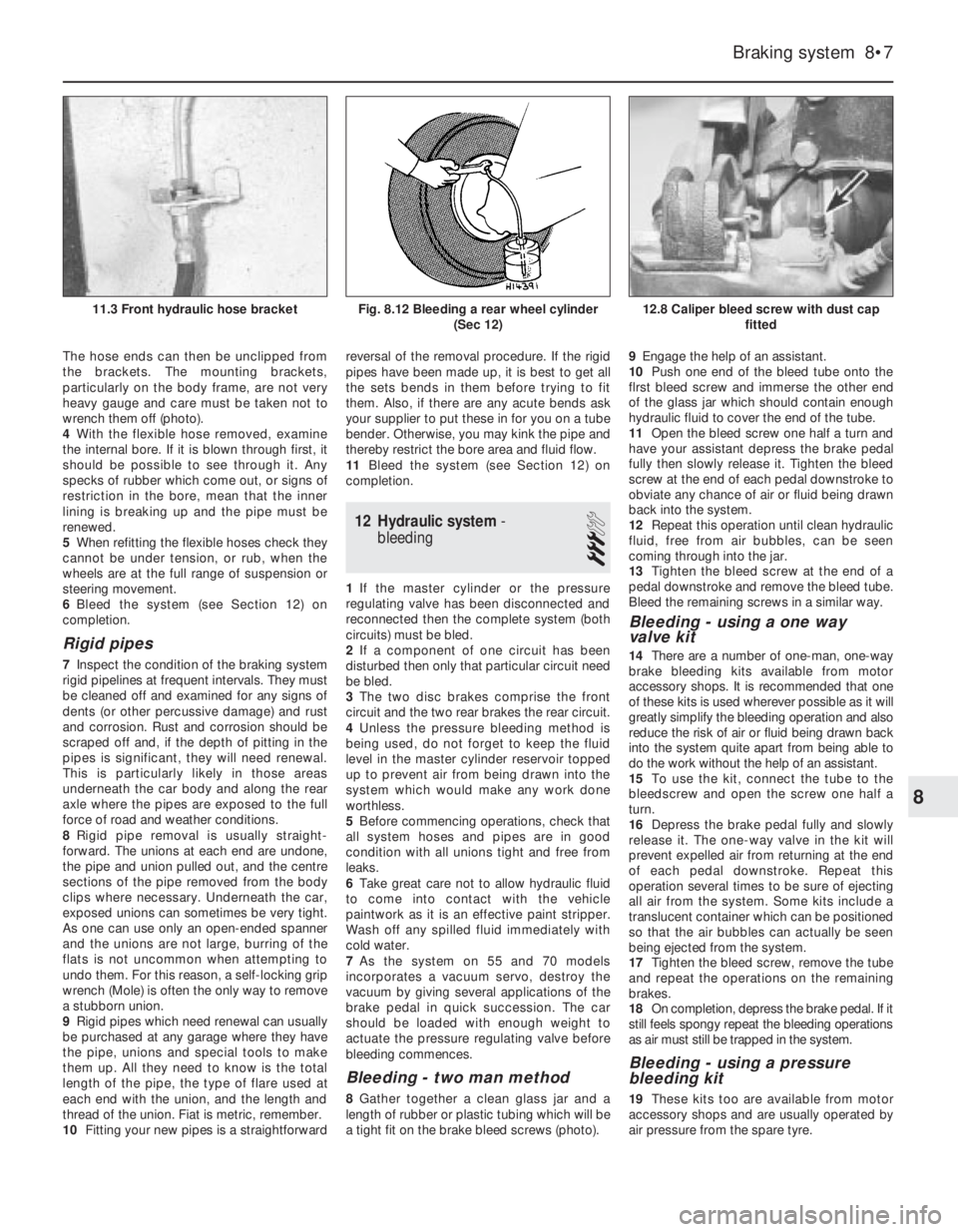
The hose ends can then be unclipped from
the brackets. The mounting brackets,
particularly on the body frame, are not very
heavy gauge and care must be taken not to
wrench them off (photo).
4With the flexible hose removed, examine
the internal bore. If it is blown through first, it
should be possible to see through it. Any
specks of rubber which come out, or signs of
restriction in the bore, mean that the inner
lining is breaking up and the pipe must be
renewed.
5When refitting the flexible hoses check they
cannot be under tension, or rub, when the
wheels are at the full range of suspension or
steering movement.
6Bleed the system (see Section 12) on
completion.
Rigid pipes
7Inspect the condition of the braking system
rigid pipelines at frequent intervals. They must
be cleaned off and examined for any signs of
dents (or other percussive damage) and rust
and corrosion. Rust and corrosion should be
scraped off and, if the depth of pitting in the
pipes is significant, they will need renewal.
This is particularly likely in those areas
underneath the car body and along the rear
axle where the pipes are exposed to the full
force of road and weather conditions.
8Rigid pipe removal is usually straight-
forward. The unions at each end are undone,
the pipe and union pulled out, and the centre
sections of the pipe removed from the body
clips where necessary. Underneath the car,
exposed unions can sometimes be very tight.
As one can use only an open-ended spanner
and the unions are not large, burring of the
flats is not uncommon when attempting to
undo them. For this reason, a self-locking grip
wrench (Mole) is often the only way to remove
a stubborn union.
9Rigid pipes which need renewal can usually
be purchased at any garage where they have
the pipe, unions and special tools to make
them up. All they need to know is the total
length of the pipe, the type of flare used at
each end with the union, and the length and
thread of the union. Fiat is metric, remember.
10Fitting your new pipes is a straightforwardreversal of the removal procedure. If the rigid
pipes have been made up, it is best to get all
the sets bends in them before trying to fit
them. Also, if there are any acute bends ask
your supplier to put these in for you on a tube
bender. Otherwise, you may kink the pipe and
thereby restrict the bore area and fluid flow.
11Bleed the system (see Section 12) on
completion.
12 Hydraulic system-
bleeding
3
1If the master cylinder or the pressure
regulating valve has been disconnected and
reconnected then the complete system (both
circuits) must be bled.
2If a component of one circuit has been
disturbed then only that particular circuit need
be bled.
3The two disc brakes comprise the front
circuit and the two rear brakes the rear circuit.
4Unless the pressure bleeding method is
being used, do not forget to keep the fluid
level in the master cylinder reservoir topped
up to prevent air from being drawn into the
system which would make any work done
worthless.
5Before commencing operations, check that
all system hoses and pipes are in good
condition with all unions tight and free from
leaks.
6Take great care not to allow hydraulic fluid
to come into contact with the vehicle
paintwork as it is an effective paint stripper.
Wash off any spilled fluid immediately with
cold water.
7As the system on 55 and 70 models
incorporates a vacuum servo, destroy the
vacuum by giving several applications of the
brake pedal in quick succession. The car
should be loaded with enough weight to
actuate the pressure regulating valve before
bleeding commences.
Bleeding - two man method
8Gather together a clean glass jar and a
length of rubber or plastic tubing which will be
a tight fit on the brake bleed screws (photo).9Engage the help of an assistant.
10Push one end of the bleed tube onto the
flrst bleed screw and immerse the other end
of the glass jar which should contain enough
hydraulic fluid to cover the end of the tube.
11Open the bleed screw one half a turn and
have your assistant depress the brake pedal
fully then slowly release it. Tighten the bleed
screw at the end of each pedal downstroke to
obviate any chance of air or fluid being drawn
back into the system.
12Repeat this operation until clean hydraulic
fluid, free from air bubbles, can be seen
coming through into the jar.
13Tighten the bleed screw at the end of a
pedal downstroke and remove the bleed tube.
Bleed the remaining screws in a similar way.
Bleeding - using a one way
valve kit
14There are a number of one-man, one-way
brake bleeding kits available from motor
accessory shops. It is recommended that one
of these kits is used wherever possible as it will
greatly simplify the bleeding operation and also
reduce the risk of air or fluid being drawn back
into the system quite apart from being able to
do the work without the help of an assistant.
15To use the kit, connect the tube to the
bleedscrew and open the screw one half a
turn.
16Depress the brake pedal fully and slowly
release it. The one-way valve in the kit will
prevent expelled air from returning at the end
of each pedal downstroke. Repeat this
operation several times to be sure of ejecting
all air from the system. Some kits include a
translucent container which can be positioned
so that the air bubbles can actually be seen
being ejected from the system.
17Tighten the bleed screw, remove the tube
and repeat the operations on the remaining
brakes.
18On completion, depress the brake pedal. If it
still feels spongy repeat the bleeding operations
as air must still be trapped in the system.
Bleeding - using a pressure
bleeding kit
19These kits too are available from motor
accessory shops and are usually operated by
air pressure from the spare tyre.
Braking system 8•7
12.8 Caliper bleed screw with dust cap
fittedFig. 8.12 Bleeding a rear wheel cylinder
(Sec 12)11.3 Front hydraulic hose bracket
8
Page 88 of 303
20By connecting a pressurised container to
the master cylinder fluid reservoir, bleeding is
then carried out by simply opening each bleed
screw in turn and allowing the fluid to run out,
rather like turning on a tap, until no air is
visible in the expelled fluid.
21By using this method, the large reserve of
hydraulic fluid provides a safeguard against
air being drawn into the master cylinder
during bleeding which often occurs if the fluid
level in the reservoir is not maintained.
22Pressure bleeding is particularly effective
when bleeding “difficult” systems or when
bleeding the complete system at time of
routine fluid renewal.
All methods
23When bleeding is completed, check and
top up the fluid level in the master cylinder
reservoir.
24Check the feel of the brake pedal. If it
feels at all spongy, air must still be present in
the system and further bleeding is indicated.
Failure to bleed satisfactorily after a
reasonable period of the bleeding operation,
may be due to worn master cylinder seals.
25Discard brake fluid which has been
expelled. lt is almost certain to be
contaminated with moisture, air and dirt
making it unsuitable for further use. Clean
fluid should always be stored in an airtight
container as it absorbs moisture readily
(hygroscopic) which lowers its boiling point
and could affect braking performance under
severe conditions.
13 Vacuum servo unit-
description
A vacuum servo unit is fitted into the brake
hydraulic circuit on 55 and 70 models in series
with the master cylinder, to provide assistance
to the driver when the brake pedal is
depressed. This reduces the effort required by
the driver to operate the brakes under all
braking conditions.
The unit operates by vacuum obtained from
the induction manifold and comprises basically
a booster diaphragm and non-return valve. The
servo unit and hydraulic master cylinder are
connected together so that the servo unit
piston rod acts as the master cylinder pushrod.
The driver’s braking effort is transmitted
through another pushrod to the servo unit
piston and its built-in control system. The servo
unit piston does not fit tightly into the cylinder,
but has a strong diaphragm to keep its edges
in constant contact with the cylinder wall, so
assuring an air tight seal between the two
parts. The forward chamber is held under
vacuum conditions created in the inlet manifold
of the engine and, during periods when the
brake pedal is not in use, the controls open a
passage to the rear chamber so placing it
under vacuum conditions as well. When the
brake pedal is depressed, the vacuum passageto the rear chamber is cut off and the chamber
opened to atmospheric pressure. The
consequent rush of air pushes the servo piston
forward in the vacuum chamber and operates
the main pushrod to the master cylinder.
The controls are designed so that
assistance is given under all conditions and,
when the brakes are not required, vacuum in
the rear chamber is established when the
brake pedal is released. All air from the
atmosphere entering the rear chamber is
passed through a small air filter.
Under normal operating conditions, the
vacuum servo unit is very reliable and does
not require overhaul except at very high
mileages. In this case, it is far better to obtain
a service exchange unit, rather than repair the
original unit.
It is emphasised that the servo unit assists
in reducing the braking effort required at the
foot pedal and in the event of its failure, the
hydraulic braking system is in no way affected
except that the need for higher pressures will
be noticed.
14 Vacuum servo unit-
servicing and testing
1Regularly, check that the vacuum hose
which runs between the servo unit and the
inlet manifold is in good condition and is a
tight fit at both ends.
2If broken or badly clogged, renew the air
filter which is located around the brake pedal
push rod. Access to this is obtained by
disconnecting the pushrod from the
cross-shaft or pedal arm, withdrawing the
pushrod, dust excluding boot and end cap.
3If the new filter is cut diagonally from its
centre hole, future renewal can be carried out
without the need for disconnection of the
pushrod.
4If the efficiency of the servo unit is suspect,
it can be checked out in the following way.
5Run the engine, then switch off the ignition.
Depress the footbrake pedal; the distinctive
in-rush of air into the servo should be clearly
heard. It should be possible to repeat this
operation several times before the vacuum in
the system is exhausted.
6Start the engine and have an assistant
apply the footbrake pedal and hold it down.
Disconnect the vacuuum hose from the servo.
There should not be any in-rush of air into the
servo through the connecting stub. lf there is,
the servo diaphragm is probably faulty. During
this test, expect the engine to idle roughly,
unless the open end of the hose to the inlet
manifold is plugged. Reconnect the hose.
7With the engine off, depress the brake
pedal fully. Start the engine with the brake
pedal still depressed; the pedal should be felt
to go down fractionally.
8If the results of these tests are not
satisfactory, remove the unit and fit a new one
as described in the next Section.
15 Vacuum servo unit-
removal and refitting
3
1Syphon as much fluid as possible out of the
master cylinder reservolr.
2Disconnect electrical leads from the
terminals in the reservoir cap then uncouple
the rigid pipelines from the master cylinder
body. Be prepared to catch leaking fluid and
plug the open ends of the pipelines.
3The master cylinder can be unbolted now
from the servo unit, or detached later when
the complete assembly is withdrawn.
4Working inside the car, disconnect the
servo pushrod from the pedal then remove the
servo mounting nuts.
5Withdraw the servo assembly into the
engine compartment, then remove it to the
bench. lf the master cylinder is still attached,
cover the wings with protective sheeting, in
case brake fluid is spilled during removal.
6Refitting is a reversal of the removal
process, but adjust the pushrod clearance as
described in Section 9. On completion of
refitting, bleed the complete hydraulic system
as described in Section 12. Note: Where the
help of an assistant is available, the servo
pushrod need not be disconnected from the
pedal. The rod is a sliding fit in the servo and
the servo can be simply pulled off the rod.
Refitting without having disconnected the rod
from the pedal can be difficult unless the help
of an assistant is available.
16 Handbrake- adjustment
1
Adjustment is normally automatic, by the
movement of the rear brake shoes on their
automatic adjusters.
However, owing to cable stretch,
supplementary adjustment is occasionally
required at the control lever adjuster nut. The
need for this adjustment is usually indicated
by excessive movement of the control lever
when fully applied.
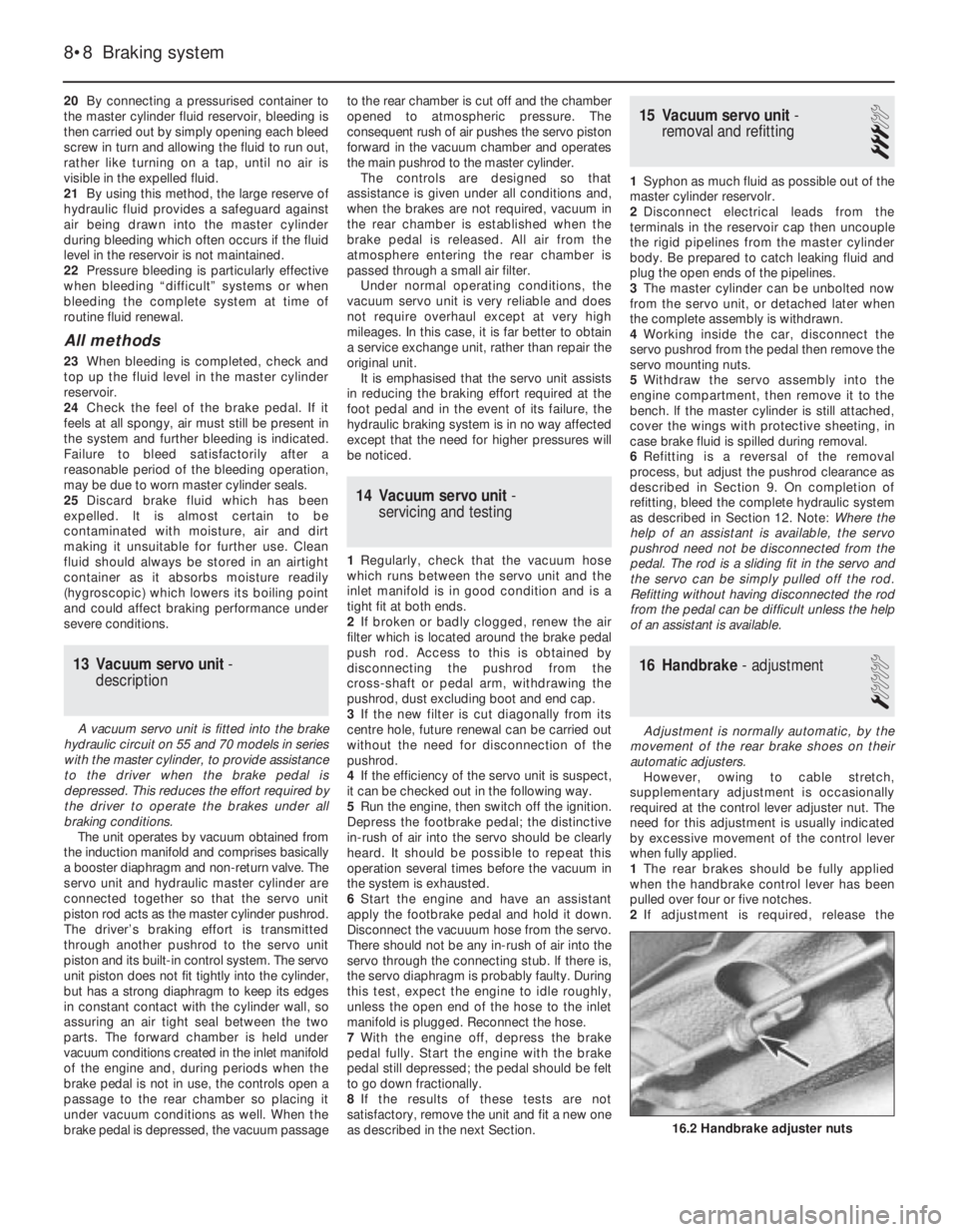
1The rear brakes should be fully applied
when the handbrake control lever has been
pulled over four or five notches.
2If adjustment is required, release the
8•8 Braking system
16.2 Handbrake adjuster nuts
Page 127 of 303
Cooling system................................................................................. 8
Part A: 999 cc engine
Description
Maintenance
Thermostat - removal and refitting
Coolant pump - removal and refitting
Part B: 1301 cc Turbo ie engine
Description
Part C: 1372 cc ie and 1372 cc Turbo ie engines
Description
Maintenance
Cooling system - draining, flushing and refilling
Radiator (and cooling fan) - removal and refitting
Thermostat - removal and refitting
Coolant pump - removal and refitting
Coolant pump/alternator drivebelt - checking, renewal and
tensioning
Part D: Heater unit later models
Heater unit - removal and refitting
Heater unit - dismantling and reassembly
Fuel and exhaust systems............................................................... 9
Part A: General
Unleaded fuel
Air cleaner modified types
Fuel pump (999 cc engine) - description, removal and
refitting
Fuel tank (999 cc engine)
Part B: Carburettor models
Carburettor (Weber 32 TLF) - description
Carburettor (Weber 32 TLF) - idle speed and mixture
Carburettor (Weber 32 TLF) - removal and refitting
Carburettor (Weber 32 TLF) - overhaul
Carburettor (Weber 30/32 DMTE) - general
Carburettor (Weber 30/32 DMTE) - overhaul
Carburettor (Weber 32 ICEV 61/250 and DMTE 30/32,
DMTE 30/150) - general
Carburettor (Solex C 30/32-CIC 8) - description
Part C: Bosch LE-2 Jetronic fuel injection system
Description
Maintenance
Fuel filter - renewal
Air cleaner element - renewal
Idle speed and mixture - adjustment
Fuel injection system - electrical tests
Fuel injection system - mechanical tests
Fuel injection system components - removal and
refitting
Throttle control linkage - general
Fuel tank - general
Part D: Bosch Mono-Jetronic fuel injection system
Description
Maintenance
Fuel filter - renewal
Air cleaner element - renewal
Idle speed and mixture adjustment
Accelerator control system - check and adjustment
Fuel system - depressurisation
Fuel pump and supply - system checks
Fuel pump - removal and refitting
Injector unit - removal and refitting
Intake air temperature sensor - removal and refitting
Fuel injector - removal and refitting
Electronic control unit (ECU) - removal and refitting
Inlet manifold - removal and refitting
Exhaust manifold - removal and refitting
Catalytic converter - general information
Fuel evaporation control system - generalPart E: Bosch L3.1/2 Jetronic fuel injection systems
Description
Fuel system - depressurisation
Maintenance
Fuel filter - renewal
Air cleaner element - renewal
Checks and adjustments
Injection system components - removal and refitting
Part G: Turbocharger system
Description
Precautions
Turbocharger (1301 cc ie engine) - removal and refitting
Turbocharger (1372 cc ie engine) - removal and refitting
Intercooler - removal and refitting
Injector cooling fan - removal and refitting
Fault finding - fuel injection system
Fault finding - turbocharger system
Ignition system................................................................................. 10
General
Ignition timing (all later models)
Breakerless ignition system - description
Distributor (breakerless type) - removal and refitting
Distributor (breakerless type) - overhaul
Breakerless ignition system components - testing
Microplex ignition system - description
Distributor (Microplex) - removal and refitting
Microplex ignition system components - testing
Digiplex 2 ignition system - description
Distributor (Digiplex 2) - removal and refitting
Spark plugs and HT leads - general
Fault finding - Microplex ignition system
Clutch................................................................................................ 11
Clutch pedal adjustment (cable clutch)
Hydraulic clutch - description
Maintenance (hydraulic clutch)
Clutch master cylinder - removal, overhaul and
refitting
Clutch operating cylinder - removal, overhaul and
refitting
Clutch hydraulic system - bleeding
Transmission.................................................................................... 12
Part A: 1301 cc Turbo ie engine
Description
Gearchange linkage - removal and refitting
Gearchange linkage (Antiskid models) - general
Final drive output shafts - description and oil seal
renewal
Part B: 1372 cc ie and 1372 cc Turbo ie engines
Description
Maintenance
Oil level - checking
Oil - renewal
Gearlever and linkages - general
Transmission - removal and refitting
Part C: 999 and 1108 cc with C514 type transmission
Description
Maintenance
Driveshafts........................................................................................ 13
Inboard joint boots (non-Turbo models, September 1987 on) -
modification
Intermediate driveshaft (Turbo ie models)
Inboard CV joints (Turbo ie models - overhaul
Right-hand driveshaft damper weight (1108 and 1372 cc
models) - removal and refitting
13•2 Supplement: Revisions and information on later models
Page 219 of 303
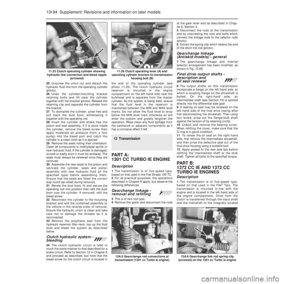
25Unscrew the union nut and detach the
hydraulic fluid line from the operating cylinder
(photo).
26Undo the cylinder/mounting bracket
retaining bolts and lift clear the cylinder
together with the bracket (photo). Release the
retaining clip and separate the cylinder from
the bracket.
27To dismantle the cylinder, prise free and
pull back the dust boot, withdrawing it
together with the operating rod.
28Invert the cylinder and shake free the
piston and seal assembly. If it is stuck inside
the cylinder, remove the bleed screw then
apply moderate air pressure (from a foot
pump) into the bleed port and catch the
cylinder in a clean cloth as it is ejected.
29Remove the seals noting their orientation.
Clean all components in methylated spirits or
new hydraulic fluid. If the cylinder is damaged,
scored or badly worn it must be renewed. The
seals must always be renewed once they are
removed.
30Assemble the new seals to the piston and
lubricate the cylinder, seals and piston
assembly with new hydraulic fluid (of the
specified type) before assembling them.
Ensure that the seals are fitted the correct
way round (as noted during removal).
31Renew the dust boot, fit and secure the
operating rod into position then refit the dust
boot over the cylinder. If removed, refit the
bleed screw.
32Reconnect the cylinder to the mounting
bracket and refit the combined assembly to
the vehicle in the reverse order of removal.
Ensure the hydraulic union is clean and take
care not to damage the threads as it is
reconnected.
33Remove the polythene seal from the
hydraulic reservoir filler neck, top up the fluid
level and bleed the system as described
below.
Clutch hydraulic system -
bleeding#
34The clutch hydraulic circuit is bled in
much the same manner to that described for a
brake circuit. Refer to Section 12 in Chapter 8
and proceed as described, but note that the
bleed screw for the clutch circuit is located inthe end of the operating cylinder (see
photo 11.25). The clutch hydraulic circuit
reservoir is mounted in the engine
compartment on the left-hand side near the
bulkhead and is separate from the master
cylinder. As the system is being bled, ensure
that the fluid level in the reservoir is
maintained between the MIN and MAX level
marks. Do not allow the fluid level to drop
below the MIN level mark otherwise air will
enter the system and greatly lengthen the
operation. Wipe clean any fluid spillage from
the paintwork or adjacent components as it
has a corrosive effect if left.
12 Transmission
PART A:
1301 CC TURBO IE ENGINE
Description
1The transmission is of five-speed type,
based on that used in the Fiat Strada 105 TC.
2For all practical purposes, the operations
described in Chapter 6 apply, but observe the
following differences.
Gearchange linkage -
removal and refitting Á
3This is of two-rod type.
4Remove the gaiter and disconnect the rodsat the gear lever end as described in Chap-
ter 6, Section 3.
5Disconnect the rods at the transmission
end by unscrewing the nuts and bolts which
connect the linkage rods to the selector rods
(photo).
6Extract the spring clip which retains the end
of the short link rod (photo).
Gearchange linkage
(Antiskid models) - general
7The gearchange linkage and internal
selector arrangement has been modified, as
shown in Fig. 13.89.
Final drive output shafts -
description and
oil seal renewal
#
8The output shafts on this transmission
incorporate a flange on the left-hand side, to
which a coupling flange on the driveshaft is
bolted. On the right-hand side, an
intermediate shaft (see Section 13) is splined
directly into the differential side gear.
9A leaking oil seal may be renewed on the
left-hand side of the final drive casing after
first disconnecting the driveshaft. Then using
two levers, prise out the flange/stub shaft
against the tension of its retaining circlip.
10Unbolt and remove the bearing cover.
When refitting the cover, make sure that the
O-ring is in good condition.
11To renew the oil seal on the right-hand
side, first remove the intermediate driveshaft,
and then prise the defective seal out of the
final drive housing using a suitable tool.
12Apply grease to the new seal lips before
refitting the intermediate shaft or the stub
shaft. Tighten all bolts to the specified torque.
PART B:
1372 CC IE AND 1372 CC
TURBO IE ENGINES
Description
1The transmission is of five-speed type,
based on that used in the FIAT Tipo. The
transmission is mounted in-line with the
engine and is located in the left-hand side of
the engine compartment. Drive from the
clutch is transferred through the input shaft
and the mainshaft to the integrally-located
13•94 Supplement: Revisions and information on later models
12A.6 Gearchange link rod spring clip
(arrowed) on the 1301 cc Turbo ie engine12A.5 Gearchange rod connections at
transmission (1301 cc Turbo ie engine)
11.26 Clutch operating lever (A) and
operating cylinder bracket-to-transmission
housing bolt (B)11.25 Clutch operating cylinder showing
hydraulic line connection and bleed nipple
(arrowed)
Page 284 of 303
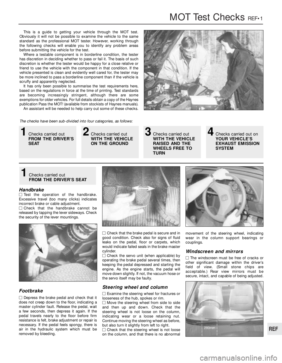
MOT Test ChecksREF•1
This is a guide to getting your vehicle through the MOT test.
Obviously it will not be possible to examine the vehicle to the same
standard as the professional MOT tester. However, working through
the following checks will enable you to identify any problem areas
before submitting the vehicle for the test.
Where a testable component is in borderline condition, the tester
has discretion in deciding whether to pass or fail it. The basis of such
discretion is whether the tester would be happy for a close relative or
friend to use the vehicle with the component in that condition. If the
vehicle presented is clean and evidently well cared for, the tester may
be more inclined to pass a borderline component than if the vehicle is
scruffy and apparently neglected.
It has only been possible to summarise the test requirements here,
based on the regulations in force at the time of printing. Test standards
are becoming increasingly stringent, although there are some
exemptions for older vehicles. For full details obtain a copy of the Haynes
publication Pass the MOT! (available from stockists of Haynes manuals).
An assistant will be needed to help carry out some of these checks.
The checks have been sub-divided into four categories, as follows:
HandbrakeMTest the operation of the handbrake.
Excessive travel (too many clicks) indicates
incorrect brake or cable adjustment.
MCheck that the handbrake cannot be
released by tapping the lever sideways. Check
the security of the lever mountings.
Footbrake
MDepress the brake pedal and check that it
does not creep down to the floor, indicating a
master cylinder fault. Release the pedal, wait
a few seconds, then depress it again. If the
pedal travels nearly to the floor before firm
resistance is felt, brake adjustment or repair is
necessary. If the pedal feels spongy, there is
air in the hydraulic system which must be
removed by bleeding.MCheck that the brake pedal is secure and in
good condition. Check also for signs of fluid
leaks on the pedal, floor or carpets, which
would indicate failed seals in the brake master
cylinder.
MCheck the servo unit (when applicable) by
operating the brake pedal several times, then
keeping the pedal depressed and starting the
engine. As the engine starts, the pedal will
move down slightly. If not, the vacuum hose or
the servo itself may be faulty.
Steering wheel and column
MExamine the steering wheel for fractures or
looseness of the hub, spokes or rim.
MMove the steering wheel from side to side
and then up and down. Check that the
steering wheel is not loose on the column,
indicating wear or a loose retaining nut.
Continue moving the steering wheel as before,
but also turn it slightly from left to right.
MCheck that the steering wheel is not loose
on the column, and that there is no abnormalmovement of the steering wheel, indicating
wear in the column support bearings or
couplings.
Windscreen and mirrors
MThe windscreen must be free of cracks or
other significant damage within the driver’s
field of view. (Small stone chips are
acceptable.) Rear view mirrors must be
secure, intact, and capable of being adjusted.
1Checks carried out
FROM THE DRIVER’S SEAT
1Checks carried out
FROM THE DRIVER’S
SEAT2Checks carried out
WITH THE VEHICLE
ON THE GROUND3Checks carried out
WITH THE VEHICLE
RAISED AND THE
WHEELS FREE TO
TURN4Checks carried out on
YOUR VEHICLE’S
EXHAUST EMISSION
SYSTEM
REF
Page 288 of 303
Introduction
A selection of good tools is a fundamental
requirement for anyone contemplating the
maintenance and repair of a motor vehicle.
For the owner who does not possess any,
their purchase will prove a considerable
expense, offsetting some of the savings made
by doing-it-yourself. However, provided that
the tools purchased meet the relevant national
safety standards and are of good quality, they
will last for many years and prove an
extremely worthwhile investment.
To help the average owner to decide which
tools are needed to carry out the various tasks
detailed in this manual, we have compiled
three lists of tools under the following
headings: Maintenance and minor repair,
Repair and overhaul, and Special. Newcomers
to practical mechanics should start off with
the Maintenance and minor repairtool kit, and
confine themselves to the simpler jobs around
the vehicle. Then, as confidence and
experience grow, more difficult tasks can be
undertaken, with extra tools being purchased
as, and when, they are needed. In this way, a
Maintenance and minor repairtool kit can be
built up into a Repair and overhaultool kit over
a considerable period of time, without any
major cash outlays. The experienced do-it-
yourselfer will have a tool kit good enough for
most repair and overhaul procedures, and will
add tools from the Specialcategory when it is
felt that the expense is justified by the amount
of use to which these tools will be put.
Maintenance and minor repair
tool kit
The tools given in this list should be
considered as a minimum requirement if
routine maintenance, servicing and minor
repair operations are to be undertaken. We
recommend the purchase of combination
spanners (ring one end, open-ended the
other); although more expensive than open-
ended ones, they do give the advantages of
both types of spanner.
MCombination spanners: 8, 9, 10, 11, 12, 13,
14, 15, 16, 17, 19, 21, 22, 24 & 26 mm
MAdjustable spanner - 35 mm jaw (approx)
MSet of feeler gauges
MSpark plug spanner (with rubber insert)
MSpark plug gap adjustment tool
MBrake bleed nipple spannerMScrewdrivers: Flat blade and cross blade –
approx 100 mm long x 6 mm dia
MCombination pliers
MHacksaw (junior)
MTyre pump
MTyre pressure gauge
MOil can
MOil filter removal tool
MFine emery cloth
MWire brush (small)
MFunnel (medium size)
Repair and overhaul tool kit
These tools are virtually essential for
anyone undertaking any major repairs to a
motor vehicle, and are additional to those
given in the Maintenance and minor repairlist.
Included in this list is a comprehensive set of
sockets. Although these are expensive, they
will be found invaluable as they are so
versatile - particularly if various drives are
included in the set. We recommend the half-
inch square-drive type, as this can be used
with most proprietary torque wrenches. If you
cannot afford a socket set, even bought
piecemeal, then inexpensive tubular box
spanners are a useful alternative.
The tools in this list will occasionally need
to be supplemented by tools from the Special
list:
MSockets (or box spanners) to cover range in
previous list
MReversible ratchet drive (for use with
sockets) (see illustration)
MExtension piece, 250 mm (for use with
sockets)
MUniversal joint (for use with sockets)
MTorque wrench (for use with sockets)
MSelf-locking grips
MBall pein hammer
MSoft-faced mallet (plastic/aluminium or
rubber)
MScrewdrivers:
Flat blade - long & sturdy, short (chubby),
and narrow (electrician’s) types
Cross blade - Long & sturdy, and short
(chubby) types
MPliers:
Long-nosed
Side cutters (electrician’s)
Circlip (internal and external)
MCold chisel - 25 mm
MScriber
MScraperMCentre-punch
MPin punch
MHacksaw
MBrake hose clamp
MBrake bleeding kit
MSelection of twist drills
MSteel rule/straight-edge
MAllen keys
MSelection of files
MWire brush
MAxle stands
MJack (strong trolley or hydraulic type)
MLight with extension lead
Special tools
The tools in this list are those which are not
used regularly, are expensive to buy, or which
need to be used in accordance with their
manufacturers’ instructions. Unless relatively
difficult mechanical jobs are undertaken
frequently, it will not be economic to buy
many of these tools. Where this is the case,
you could consider clubbing together with
friends (or joining a motorists’ club) to make a
joint purchase, or borrowing the tools against
a deposit from a local garage or tool hire
specialist. It is worth noting that many of the
larger DIY superstores now carry a large
range of special tools for hire at modest rates.
The following list contains only those tools
and instruments freely available to the public,
and not those special tools produced by the
vehicle manufacturer specifically for its dealer
network. You will find occasional references
to these manufacturers’ special tools in the
text of this manual. Generally, an alternative
method of doing the job without the vehicle
manufacturers’ special tool is given. However,
sometimes there is no alternative to using
them. Where this is the case and the relevant
tool cannot be bought or borrowed, you will
have to entrust the work to a franchised
garage.
MValve spring compressor (see illustration)
MValve grinding tool
MPiston ring compressor (see illustration)
MPiston ring removal/installation tool (see
illustration)
MCylinder bore hone (see illustration)
MBalljoint separator
MCoil spring compressors (where applicable)
MTwo/three-legged hub and bearing puller
(see illustration)
Tools and Working FacilitiesREF•5
REF
Page 296 of 303
Glossary of Technical TermsREF•13
REF
A
ABS (Anti-lock brake system)A system,
usually electronically controlled, that senses
incipient wheel lockup during braking and
relieves hydraulic pressure at wheels that are
about to skid.
Air bag An inflatable bag hidden in the
steering wheel (driver’s side) or the dash or
glovebox (passenger side). In a head-on
collision, the bags inflate, preventing the
driver and front passenger from being thrown
forward into the steering wheel or windscreen.
Air cleanerA metal or plastic housing,
containing a filter element, which removes
dust and dirt from the air being drawn into the
engine.
Air filter elementThe actual filter in an air
cleaner system, usually manufactured from
pleated paper and requiring renewal at regular
intervals.
Allen keyA hexagonal wrench which fits into
a recessed hexagonal hole.
Alligator clipA long-nosed spring-loaded
metal clip with meshing teeth. Used to make
temporary electrical connections.
AlternatorA component in the electrical
system which converts mechanical energy
from a drivebelt into electrical energy to
charge the battery and to operate the starting
system, ignition system and electrical
accessories.
Ampere (amp)A unit of measurement for the
flow of electric current. One amp is the
amount of current produced by one volt
acting through a resistance of one ohm.
Anaerobic sealerA substance used to
prevent bolts and screws from loosening.
Anaerobic means that it does not require
oxygen for activation. The Loctite brand is
widely used.
AntifreezeA substance (usually ethylene
glycol) mixed with water, and added to a
vehicle’s cooling system, to prevent freezing
of the coolant in winter. Antifreeze also
contains chemicals to inhibit corrosion and
the formation of rust and other deposits that
would tend to clog the radiator and coolant
passages and reduce cooling efficiency.
Anti-seize compoundA coating that
reduces the risk of seizing on fasteners that
are subjected to high temperatures, such as
exhaust manifold bolts and nuts.
AsbestosA natural fibrous mineral with great
heat resistance, commonly used in the
composition of brake friction materials.Asbestos is a health hazard and the dust
created by brake systems should never be
inhaled or ingested.
AxleA shaft on which a wheel revolves, or
which revolves with a wheel. Also, a solid
beam that connects the two wheels at one
end of the vehicle. An axle which also
transmits power to the wheels is known as a
live axle.
AxleshaftA single rotating shaft, on either
side of the differential, which delivers power
from the final drive assembly to the drive
wheels. Also called a driveshaft or a halfshaft.
BBall bearingAn anti-friction bearing
consisting of a hardened inner and outer race
with hardened steel balls between two races.
BearingThe curved surface on a shaft or in a
bore, or the part assembled into either, that
permits relative motion between them with
minimum wear and friction.
Big-end bearingThe bearing in the end of
the connecting rod that’s attached to the
crankshaft.
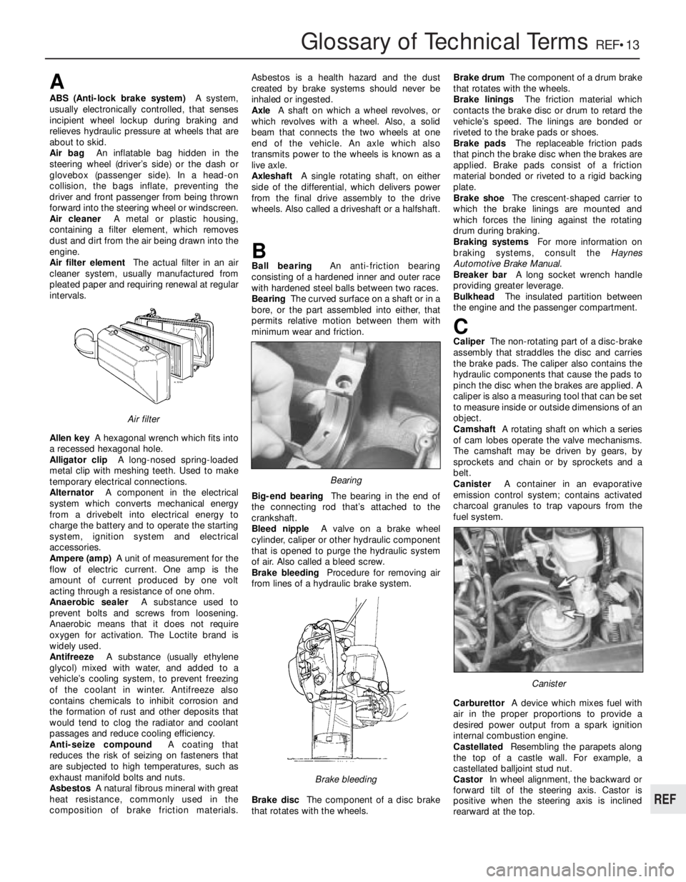
Bleed nippleA valve on a brake wheel
cylinder, caliper or other hydraulic component
that is opened to purge the hydraulic system
of air. Also called a bleed screw.
Brake bleedingProcedure for removing air
from lines of a hydraulic brake system.
Brake discThe component of a disc brake
that rotates with the wheels.Brake drumThe component of a drum brake
that rotates with the wheels.
Brake liningsThe friction material which
contacts the brake disc or drum to retard the
vehicle’s speed. The linings are bonded or
riveted to the brake pads or shoes.
Brake padsThe replaceable friction pads
that pinch the brake disc when the brakes are
applied. Brake pads consist of a friction
material bonded or riveted to a rigid backing
plate.
Brake shoeThe crescent-shaped carrier to
which the brake linings are mounted and
which forces the lining against the rotating
drum during braking.
Braking systemsFor more information on
braking systems, consult the Haynes
Automotive Brake Manual.
Breaker barA long socket wrench handle
providing greater leverage.
BulkheadThe insulated partition between
the engine and the passenger compartment.
CCaliperThe non-rotating part of a disc-brake
assembly that straddles the disc and carries
the brake pads. The caliper also contains the
hydraulic components that cause the pads to
pinch the disc when the brakes are applied. A
caliper is also a measuring tool that can be set
to measure inside or outside dimensions of an
object.
CamshaftA rotating shaft on which a series
of cam lobes operate the valve mechanisms.
The camshaft may be driven by gears, by
sprockets and chain or by sprockets and a
belt.
CanisterA container in an evaporative
emission control system; contains activated
charcoal granules to trap vapours from the
fuel system.
CarburettorA device which mixes fuel with
air in the proper proportions to provide a
desired power output from a spark ignition
internal combustion engine.
CastellatedResembling the parapets along
the top of a castle wall. For example, a
castellated balljoint stud nut.
CastorIn wheel alignment, the backward or
forward tilt of the steering axis. Castor is
positive when the steering axis is inclined
rearward at the top.
Canister
Brake bleeding
Bearing
Air filter
Page 300 of 303
A
Accelerator cable - 3•12, 13•80
Accelerator control system - 13•75
Accelerator pump -3•7, 3•8, 3•11, 13•66
Acknowledgements - 0•4
Aerial -9•10
Air bags - 0•5
Air cleaner -3•4, 13•60, 13•69, 13•67,
13•75, 13•79
Air pressure switch - 13•70
Air temperature sensor - 13•76
Airflow meter - 13•67, 13•69, 13•80
Alternator -9•3, 13•58, 13•103, 13•104
Alternator fault -9•14
Anti-flooding device -3•8, 3•9, 3•10, 3•11,
13•64
Anti-knock sensor - 13•86, 13•90
Anti-roll bar - 13•111
Antifreeze - 0•6, 0•13, 2•1, 2•2
Antiskid system - 13•103
Armrest - 13•112
Asbestos - 0•5
Auxiliary shaft -1•29, 1•30, 13•51, 13•53
B
Battery -0•5, 9•2
Battery fault -9•14
Bleeding brakes -8•7
Bleeding clutch - 13•94
Bodywork- 12•1et seq, 13•111, REF•4
Bonnet - 12•3, 12•4
Boots -7•2, 10•2, 13•98
Brake fluid -0•13, 8•1, 13•110, 13•111
Braking system-8•1et seq, 13•100,
REF•1, REF•2, REF•3
Braking system fault finding -8•9
Breakerless ignition system - 13•85, 13•86
Bumpers - 12•4, 12•11, 13•113
Burning -0•5
C
Cables -3•12, 5•1, 8•9, 9•8, 13•80
Calipers -8•3, 13•101, 13•102Camshaft -1•19, 1•21, 1•24, 1•29, 1•32,
13•21, 13•30, 13•34, 13•41, 13•42
Capacities -0•6, 13•17
Carburettors -3•6 to 3•11, 13•62 to 13•66
Carpets - 12•2
Cassette player-9•10
Catalytic converter - 13•77
Central door locking -9•11, 13•109
Centre console - 12•9
Check control (warning module) system -
9•12, 9•13, 13•110, 13•111
Choke -3•11, 3•12
Cigar lighter -9•13, 13•109
Clock -9•13, 13•108
Clutch-5•1et seq, 13•83, 13•92, 13•94
Clutch fault finding -5•3
Clutch fluid -0•13
CO emissions (mixture) - REF•4
Coil -4•6, 13•86, 13•90, 13•91
Coil spring - 11•3, 11•4
Condenser -4•5
Connecting rods -1•12, 1•18, 1•22, 1•26,
1•30, 13•25, 13•26, 13•30, 13•35,
13•47, 13•48, 13•53
Console - 12•9
Constant velocity joint -0•13, 7•3, 13•98,
13•99
Contact breaker points -4•2, 4•3
Contents -0•2
Control panel - 13•108
Conversion factors -0•14
Coolant -0•6, 0•13, 2•1, 2•2, 13•69, 13•70,
13•110, 13•111
Coolant pump -2•4, 13•55, 13•58
Cooling and heating systems-2•1et seq,
13•54, 13•55
Cooling and heating systems fault finding -
2•8
Courtesy lamp -9•5, 9•8
Crankcase -1•17
Crankcase ventilation system -1•8
Crankshaft -1•18, 1•20, 1•30, 1•31, 13•44,
13•45, 13•52
Crossmember - 11•4
Crushing -0•5
CV joints -0•13, 7•3, 13•98, 13•99
Cylinder block -1•17Cylinder head -1•10, 1•16, 1•19, 1•22,
1•25, 1•28, 1•32, 13•19, 13•22, 13•30,
13•34, 13•43, 13•44, 13•53
D
Dents in bodywork - 12•2
Depressurisation (fuel system) - 13•75
Digiplex 2 ignition system - 13•90
Dim-dip system - 13•106
Dimensions -0•6, 13•17
Direction indicators -9•7
Discs -8•4, 13•101, 13•102
Distributor -4•3, 4•5, 13•86, 13•89, 13•90,
13•92
Doors -9•11, 12•5, 12•6, 12•7, 13•111,
13•112, 13•114, REF•2
Drivebelts -2•3, 13•58
Driveshaft
Driveshafts and hubs fault finding -7•6
Driveshafts,hubs,roadwheels and tyres-
0•13, 7•1et seq, 10•4, 11•3, 11•6,
13•98, 13•99, REF•3, REF•4
Drums -8•4
Dwell angle -4•4
E
Economy gauge (Econometer) -3•11, 9•12
Electric shock -0•5
Electric windows -9•11, 13•109
Electrical control circuit (ECU) - 13•67,
13•71, 13•81, 13•86, 13•90
Electrical system-9•1et seq,13•103,
REF•2
Electrical system fault finding -9•14,
REF•9
Electronic ignition -4•3, 4•6, 4•7
Engine-1•1et seq, 13•19, 13•33, 13•37
Engine fault finding -1•35, 1•36, 2•8, 3•13,
4•9, 13•92, REF•10, REF•11
Engine oil -0•6, 0•13, 1•3, 1•4, 1•8
Engine speed sensor -4•7, 13•89, 13•91
Environmental considerations - REF•8
Exhaust emission checks - REF•4
Exhaust manifold - 13•77
Exhaust system -3•12, REF•3
IndexREF•17
REF
Note: References throughout this index relate to Chapter•page number