stop start FIAT UNO 1983 Service Repair Manual
[x] Cancel search | Manufacturer: FIAT, Model Year: 1983, Model line: UNO, Model: FIAT UNO 1983Pages: 303, PDF Size: 10.36 MB
Page 37 of 303
removed and the weight of the car is again on
its roadwheels.
4Fill the cooling system.
5Fill the engine with oil.
6Replenish lost transmission oil.
7Reconnect the battery.
8Adjust the clutch pedal as described in
Chapter 5.
24 Engine- initial start-up after
overhaul or major repair
4
1Make sure that the battery is fully charged
and that all lubricants, coolant and fuel are
replenished.
2If the fuel system has been dismantled it will
require several revolutions of the engine on
the starter motor to pump the petrol up to the
carburettor.
3Turn the carburettor throttle speed screwthrough one complete turn to increase the idle
speed in order to offset the initial stiffness of
new engine internal components.
4As soon as the engine fires and runs, keep
it going at a fast idle speed and bring it up to
normal working temperature.
5As the engine warms up there will be odd
smells and some smoke from parts getting
hot and burning off oil deposits. The signs to
look for are leaks of water or oil which will be
obvious.
6Check also the exhaust pipe and manifold
connections as these do not always “find”
their exact gas tight position until the warmth
and vibration have acted on them and it is
almost certain that they will need tightening
further. This should be done, of course, with
the engine stopped.
7When normal running temperature has
been reached, adjust the engine idle speed as
described in Chapter 3.
8Stop the engine and wait a few minutes tosee if any lubricant or coolant is dripping out
when the engine is stationary.
9Road test the car to check that the timing is
correct and that the engine is giving the
necessary smoothness and power. Do not
race the engine - if new bearings and/or
pistons have been fitted it should be treated
as a new engine and run in at a reduced
speed for the first 500 km (300 miles).
10After the first 1500 km (900 miles) the
cylinder head bolts must be re-torqued in the
following way (engine cold).
11Remove the air cleaner and rocker cover.
Unscrew the first bolt (Fig. 1.7) through a
quarter turn and then tighten it to final stage 2
torque (see Specifications).
12Repeat on the remaining bolts, one at a
time.
13Check and adjust the valve clearances
(Section 5).
14Refit the rocker cover and air cleaner.
903 cc engine 1•23
26.4 Shim engraved mark26.2 Removing a shim from a cam follower25.4 Checking a valve clearance
1
Part 3: 1116 cc and 1301 cc engines
25 Valve clearances- checking
2
This should only be required if the valves
have been renewed or ground in, or at high
mileages when noise or poor engine
performance indicates that a check is
necessary.
It is important that each valve clearance is
set correct otherwise the timing will be
wrong and engine performance poor. If there
is no clearance at all, the valve and its seat
will soon burn. Always set the clearances
with the engine cold.
1Remove the camshaft cover. Jack-up a
front wheel and engage top gear so that by
turning the wheel, the crankshaft can be
rotated.
2Each valve clearance must be checked
when the high point of the cam is pointing
directly upward away from the cam follower.
3Check the clearances in the firing order
1-3-4-2, No. 1 cylinder being at the timing
belt end of the engine. This will minimise the
amount of crankshaft rotation required.4Insert the appropriate feeler blade
between the heel of the cam and the cam
follower shim of the first valve. If necessary
alter the thickness of the feeler blade until it
is a stiff, sliding fit. Record the thickness,
which will, of course, represent the valve
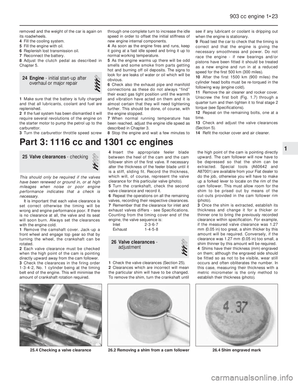
clearance for this particular valve (photo).
5Turn the crankshaft, check the second
valve clearance and record it.
6Repeat the operations on all the remaining
valves, recording their respective clearances.
7Remember that the clearance for inlet and
exhaust valves differs - see Specifications.
Counting from the timing cover end of the
engine, the valve sequence is:
Inlet 2-3-6-7
Exhaust 1-4-5-8
26 Valve clearances-
adjustment
3
1Check the valve clearances (Section 25).
2Clearances which are incorrect will mean
the particular shim will have to be changed.
To remove the shim, turn the crankshaft untilthe high point of the cam is pointing directly
upward. The cam follower will now have to
be depressed so that the shim can be
extracted. Special tools (A60642 and
A87001) are available from your Fiat dealer to
do the job, otherwise you will have to make
up a forked lever to locate on the rim of the
cam follower. This must allow room for the
shim to be prised out by means of the
cut-outs provided in the cam follower rim
(photo).
3Once the shim is extracted, establish its
thickness and change it for a thicker or
thinner one to bring the previously recorded
clearance within specification. For example,
if the measured valve clearance was 1.27
mm (0.05 in) too great, a shim thicker by this
amount will be required. Conversely, if the
clearance was 1.27 mm (0.05 in) too small, a
shim thinner by this amount will be required.
4Shims have their thickness (mm) engraved
on them; although the engraved side should
be fitted so as not to be visible, wear still
occurs and often obliterates the number. In
this case, measuring their thickness with a
metric micrometer is the only method to
establish their thickness (photo).
Page 48 of 303
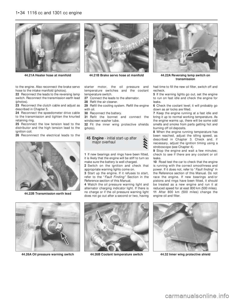
to the engine. Also reconnect the brake servo
hose to the intake manifold (photos).
22Reconnect the leads to the reversing lamp
switch. Reconnect the transmission earth lead
(photos).
23Reconnect the clutch cable and adjust as
described in Chapter 5.
24Reconnect the speedometer drive cable
to the transmission and tighten the knurled
retaining ring.
25Reconnect the low tension lead to the
distributor and the high tension lead to the
ignition coil.
26Reconnnect the electrical leads to thestarter motor, the oil pressure and
temperature switches and the coolant
temperature switch.
27Connect the leads to the alternator.
28Refit the air cleaner.
29Refill the cooling system. Refill the engine
with oil.
30Reconnect the battery.
31Refit the bonnet and connect the
windscreen washer tube.
32Fit the inner wing protective shields
(photo).
45 Engine- initial start-up after
major overhaul
4
1If new bearings and rings have been fitted,
it is likely that the engine will be stiff to turn so
make sure the battery is well charged.
2Switch on the ignition and check that
appropriate warning lights come on.
3Start up the engine. If it refuses to start,
refer to the “Fault Finding” Section in the
Reference section of this Manual.
4Watch the oil pressure warning light and
alternator charging indicator light. If there is
no charge or if the oil pressure warning light
does not go out after a second or two, havinghad time to fill the new oil filter, switch off and
recheck.
5If the warning lights go out, set the engine
to run on fast idle and check the engine for
leaks.
6Check the coolant level; it will probably go
down as air locks are filled.
7Keep the engine running at a fast idle and
bring it up to normal working temperature. As
the engine warms up, there will be some odd
smells and smoke from parts getting hot and
burning off oil deposits.
8When the engine running temperature has
been reached, adjust the idling speed, as
described in Chapter 3. Check and, if
necessary, adjust the ignition timing using a
stroboscope (see Chapter 4).
9Stop the engine and wait a few minutes;
check to see if there are any coolant or oil
leaks.
10Road test the car to check that the engine
is running with the correct smoothness and
power. If it does not, refer to “Fault finding” in
the Reference section of this Manual. Do not
race the engine. If new bearings and/or
pistons and rings have been fitted, it should
be treated as a new engine and run it at
reduced speed for at east 800 km (500 miles).
11After 800 km (500 miles) change the
engine oil and filter.
1•34 1116 cc and 1301 cc engine
44.32 Inner wing protective shield44.26B Coolant temperature switch44.26A Oil pressure warning switch
44.22B Transmission earth lead
44.22A Reversing lamp switch on
transmission44.21B Brake servo hose at manifold44.21A Heater hose at manifold
Page 49 of 303
Fault finding - all engines
Note: When investigating starting and uneven running faults, do not be tempted into snap diagnosis. Start from the beginning of the check
procedure and follow it through. It will take less time in the long run. Poor performance from an engine in terms of power and economy is not
normally diagnosed quickly. In any event, the ignition and fuel systems must be checked first before assuming any further investigation needs to
be made.
All engines 1•35
1
Engine fails to turn when starter operated
m mBattery discharged
m mBattery terminals loose or corroded
m mBattery earth to body defective
m mEngine/transmission earth strap broken or loose
m mDisconnected or broken wire in starter circuit
m mIgnition/starter switch defective
m mStarter motor or solenoid defective (see Chapter 9)
m mMajor mechanical failure (seizure) or long disuse (piston rings rusted
to bores)
Engine turns and fails to start
m mBattery discharged
m mBattery terminals loose or corroded
m mBattery or engine earth strap loose
m mStarter motor connections loose
m mOil in engine/transmission too thick
m mStarter motor defective
m mVapour lock in fuel line (in hot conditions or at high altitude)
m mBlocked float chamber needle valve
m mFuel pump filter blocked
m mChoked or blocked carburettor jets
m mFaulty fuel pump
m mFuel tank empty
m mOther fuel system fault (see Chapter 3)
m mShorted or disconnected low tension leads
m mDirty, incorrectly set, or pitted contact breaker points
m mContact breaker point spring earthed or broken
m mFaulty condenser
m mDefective ignition switch
m mFaulty coil
m mDamp or dirty HT leads, distributor cap or plug bodies
m mBroken, loose or disconnected LT leads
m mIgnition leads connected wrong way round
m mOther ignition fault (see Chapter 4)
m mValve timing incorrect (after rebuild)
Engine fires but will not run
m
mInsufficient choke (cold engine)
m mFuel starvation or tank empty
m mIgnition fault (see Chapter 4)
m mOther fuel system fault (see Chapter 3)
Engine stalls and will not restart
m
mToo much choke allowing too rich a mixture to wet plugs
m mFloat damaged or leaking or needle not seating
m mFloat lever incorrectly adjusted
m mIgnition failure - sudden
m mIgnition failure - misfiring precedes total stoppage
m mIgnition failure - in severe rain or after traversing water splash
m mNo petrol in petrol tank
m mPetrol tank breather choked
m mSudden obstruction in carburettor
m mWater in fuel system
Engine slow to warm up
m
mChoke linkage maladjusted
m mAir cleaner temperature control unit defective
m mThermostat stuck open (see Chapter 2)
m mOther fuel system fault (see Chapter 3)
Difficult starting when cold
m
mInsufficient choke
m mFouled or incorrectly gapped spark plugs
m mDamp or dirty HT leads, distributor cap or spark plug bodies
m mDirty or maladjusted contact breaker points
m mOther ignition fault or timing maladjustment (see Chapter 4)
m mFuel system or emission control fault (see Chapter 3)
m mPoor compression (may be due to incorrect valve clearances, burnt
or sticking valves, blown head gasket, worn or damaged pistons,
rings or bores)
m mIncorrect valve timing (after rebuild)
Difficult starting when hot
m
mIncorrect use of manual choke
m mFuel line vapour lock (especially in hot weather or at high altitudes)
m mIncorrect ignition timing
m mOther fuel system or emission control fault (see Chapter 3)
m mPoor compression (see above)
Engine lacks power
m
mIgnition timing incorrect
m mContact breaker points incorrectly gapped
m mIncorrectly set spark plugs
m mDirty contact breaker points
m mDistributor automatic advance and retard mechanisms not
functioning correctly
m mOther ignition system fault (see Chapter 4)
m mAir cleaner choked
m mCarburation too rich or too weak
m mFuel filter blocked
m mAir filter blocked
m mFaulty fuel pump giving top and fuel starvation
m mOther fuel system fault (see Chapter 3)
m mPoor compression
m mValve clearances incorrect
m mCarbon build-up in cylinder head
m mSticking or leaking valves
m mWeak or broken valve springs
m mWorn valve guides or stems
m mWorn pistons and piston rings
m mBurnt out valves
m mBlown cylinder head gasket (accompanied by increase in noise)
m mWorn pistons and piston rings
m mWorn or scored cylinder bore
m mBrakes binding
Engine misfires throughout speed range
m
mDefective or fouled spark plug
m mLoose, cracked or defective HT lead
m mMaladjusted, sticking or burnt valves
m mIgnition timing incorrect
m mBlown head gasket
m mFuel contaminated
m mOther ignition fault (see Chapter 4)
m mOther fuel system fault (see Chapter 3)
Poor engine braking
m
mHigh idle speed
m mOther fuel system fault (see Chapter 3)
m mLow compression
Page 54 of 303
towards the engine. Slip the belt off the
pulleys. If this is difficult, turn the crankshaft
pulley using a spanner on its retaining nut
while pressing the belt over the edge of the
pulley rim. Use this method to fit the new belt
after first having engaged it with the coolant
pump and alternator pulley grooves.
5Tension the belt as previously described.
6The tension of a new belt should be
checked and adjusted after the first few
hundred miles of running.
9 Coolant pump- removal,
overhaul and refitting
4
Note: The design of the pump differs between
the 903 cc and the other two engines, but the
removal, overhaul and refitting operations are
essentially similar.
1To gain access to the coolant pump, open
the bonnet and remove the air cleaner.
2Slacken the alternator pivot and adjustment
nuts, push the alternator in towards the
engine and slip the drivebelt from the coolant
pump pulley. Unplug and remove the
alternator.3Drain the cooling system as previously
described.
4Disconnect the hoses from the coolant
pump, also the metal coolant transfer pipe
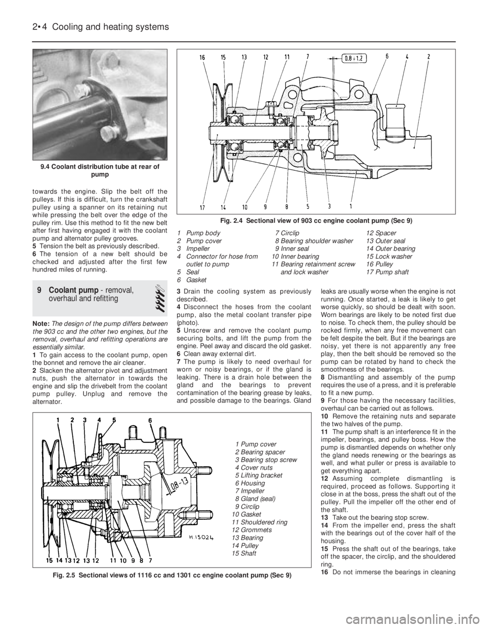
(photo).
5Unscrew and remove the coolant pump
securing bolts, and lift the pump from the
engine. Peel away and discard the old gasket.
6Clean away external dirt.
7The pump is likely to need overhaul for
worn or noisy bearings, or if the gland is
leaking. There is a drain hole between the
gland and the bearings to prevent
contamination of the bearing grease by leaks,
and possible damage to the bearings. Glandleaks are usually worse when the engine is not
running. Once started, a leak is likely to get
worse quickly, so should be dealt with soon.
Worn bearings are likely to be noted first due
to noise. To check them, the pulley should be
rocked firmly, when any free movement can
be felt despite the belt. But if the bearings are
noisy, yet there is not apparently any free
play, then the belt should be removed so the
pump can be rotated by hand to check the
smoothness of the bearings.
8Dismantling and assembly of the pump
requires the use of a press, and it is preferable
to fit a new pump.
9For those having the necessary facilities,
overhaul can be carried out as follows.
10Remove the retaining nuts and separate
the two halves of the pump.
11The pump shaft is an interference fit in the
impeller, bearings, and pulley boss. How the
pump is dismantled depends on whether only
the gland needs renewing or the bearings as
well, and what puller or press is available to
get everything apart.
12Assuming complete dismantling is
required, proceed as follows. Supporting it
close in at the boss, press the shaft out of the
pulley. Pull the impeller off the other end of
the shaft.
13Take out the bearing stop screw.
14From the impeller end, press the shaft
with the bearings out of the cover half of the
housing.
15Press the shaft out of the bearings, take
off the spacer, the circlip, and the shouldered
ring.
16Do not immerse the bearings in cleaning
2•4 Cooling and heating systems
1 Pump body
2 Pump cover
3 Impeller
4 Connector for hose from
outlet to pump
5 Seal
6 Gasket7 Circlip
8 Bearing shoulder washer
9 Inner seal
10 Inner bearing
11 Bearing retainment screw
and lock washer12 Spacer
13 Outer seal
14 Outer bearing
15 Lock washer
16 Pulley
17 Pump shaft
Fig. 2.5 Sectional views of 1116 cc and 1301 cc engine coolant pump (Sec 9)
Fig. 2.4 Sectional view of 903 cc engine coolant pump (Sec 9)
9.4 Coolant distribution tube at rear of
pump
1 Pump cover
2 Bearing spacer
3 Bearing stop screw
4 Cover nuts
5 Lifting bracket
6 Housing
7 Impeller
8 Gland (seal)
9 Circlip
10 Gasket
11 Shouldered ring
12 Grommets
13 Bearing
14 Pulley
15 Shaft
Page 55 of 303
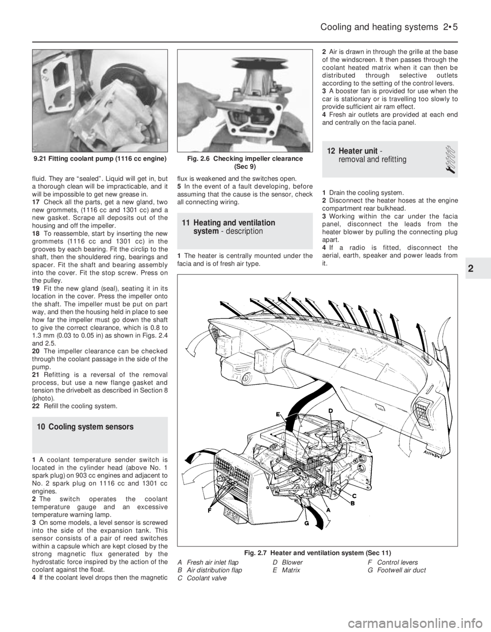
fluid. They are “sealed”. Liquid will get in, but
a thorough clean will be impracticable, and it
will be impossible to get new grease in.
17Check all the parts, get a new gland, two
new grommets, (1116 cc and 1301 cc) and a
new gasket. Scrape all deposits out of the
housing and off the impeller.
18To reassemble, start by inserting the new
grommets (1116 cc and 1301 cc) in the
grooves by each bearing. Fit the circlip to the
shaft, then the shouldered ring, bearings and
spacer. Fit the shaft and bearing assembly
into the cover. Fit the stop screw. Press on
the pulley.
19Fit the new gland (seal), seating it in its
location in the cover. Press the impeller onto
the shaft. The impeller must be put on part
way, and then the housing held in place to see
how far the impeller must go down the shaft
to give the correct clearance, which is 0.8 to
1.3 mm (0.03 to 0.05 in) as shown in Figs. 2.4
and 2.5.
20The impeller clearance can be checked
through the coolant passage in the side of the
pump.
21Refitting is a reversal of the removal
process, but use a new flange gasket and
tension the drivebelt as described in Section 8
(photo).
22Refill the cooling system.
10 Cooling system sensors
1A coolant temperature sender switch is
located in the cylinder head (above No. 1
spark plug) on 903 cc engines and adjacent to
No. 2 spark plug on 1116 cc and 1301 cc
engines.
2The switch operates the coolant
temperature gauge and an excessive
temperature warning lamp.
3On some models, a level sensor is screwed
into the side of the expansion tank. This
sensor consists of a pair of reed switches
within a capsule which are kept closed by the
strong magnetic flux generated by the
hydrostatic force inspired by the action of the
coolant against the float.
4If the coolant level drops then the magneticflux is weakened and the switches open.
5In the event of a fault developing, before
assuming that the cause is the sensor, check
all connecting wiring.
11 Heating and ventilation
system- description
1The heater is centrally mounted under the
facia and is of fresh air type.2Air is drawn in through the grille at the base
of the windscreen. It then passes through the
coolant heated matrix when it can then be
distributed through selective outlets
according to the setting of the control levers.
3A booster fan is provided for use when the
car is stationary or is travelling too slowly to
provide sufficient air ram effect.
4Fresh air outlets are provided at each end
and centrally on the facia panel.
12 Heater unit-
removal and refitting
1
1Drain the cooling system.
2Disconnect the heater hoses at the engine
compartment rear bulkhead.
3Working within the car under the facia
panel, disconnect the leads from the
heater blower by pulling the connecting plug
apart.
4If a radio is fitted, disconnect the
aerial, earth, speaker and power leads from
it.
Cooling and heating systems 2•5
Fig. 2.6 Checking impeller clearance
(Sec 9)9.21 Fitting coolant pump (1116 cc engine)
Fig. 2.7 Heater and ventilation system (Sec 11)
A Fresh air inlet flap
B Air distribution flap
C Coolant valveD Blower
E MatrixF Control levers
G Footwell air duct
2
Page 71 of 303
6On 1116 cc and 1301 cc models, the
exhaust system is of dual downpipe, two
silencer, two section type.
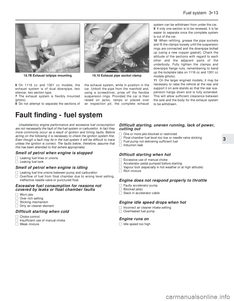
7The exhaust system is flexibly mounted
(photo).
8Do not attempt to separate the sections ofthe exhaust system, while in position in the
car. Unbolt the pipe from the manifold and,
using a screwdriver, prise off the flexible
suspension rings. Provided the car is then
raised on jacks, ramps or placed over
an inspection pit, the complete exhaust system can be withdrawn from under the car.
9If only one section is to be renewed, it is far
easier to separate once the complete system
is out of the car.
10When refitting, grease the pipe sockets
and fit the clamps loosely until the suspension
rings are connected and the downpipe bolted
up (using a new copper gasket). Check the
attitude of the sections with regard to each
other and the adjacent parts of the
underbody. Fully tighten the clamps and
downpipe flange nuts, remembering to bend
up the lockplate tabs on 1116 cc and 1301 cc
models (photo).
11On the larger engined models, it may be
necessary to raise the vehicle at the rear and
support it on axle stands so that the rear sus-
pension hangs down and is fully extended.
This will allow sufficient clearance between
the axle and the body for the exhaust system
to be withdrawn.
Fuel system 3•13
3
19.10 Exhaust pipe socket clamp19.7B Exhaust tailpipe mounting
Fault finding - fuel system
Unsatisfactory engine performance and excessive fuel consumption
are not necessarily the fault of the fuel system or carburettor. In fact they
more commonly occur as a result of ignition and timing faults. Before
acting on the following it is necessary to check the ignition system first.
Even though a fault may lie in the fuel system it will be difficult to trace
unless the ignition is correct. The faults below, therefore, assume that
this has been attended to first (where appropriate).
Smell of petrol when engine is stopped
m mLeaking fuel lines or unions
m mLeaking fuel tank
Smell of petrol when engine is idling
m
mLeaking fuel line unions between pump and carburettor
m mOverflow of fuel from float chamber due to wrong level setting,
ineffective needle valve or punctured float
Excessive fuel consumption for reasons not
covered by leaks or float chamber faults
m mWorn jets
m mOver-rich setting
m mSticking mechanism
m mDirty air cleaner element
Difficult starting when cold
m
mChoke control
m mInsufficient use of manual choke
m mWeak mixture
Difficult starting, uneven running, lack of power,
cutting out
m mOne or more jets blocked or restricted
m mFloat chamber fuel level too low or needle valve sticking
m mFuel pump not delivering sufficient fuel
m mInduction leak
Difficult starting when hot
m
mExcessive use of manual choke
m mAccelerator pedal pumped before starting
m mVapour lock (especially in hot weather or at high altitude)
m mRich mixture
Engine does not respond properly to throttle
m
mFaulty accelerator pump
m mBlocked jet(s)
m mSlack in accelerator cable
Engine idle speed drops when hot
m
mIncorrect air cleaner intake setting
m mOverheated fuel pump
Engine runs on
m
mIdle speed too high
Page 78 of 303
important that the following precautions are
observed.
3Never start the engine if the battery leads
are loose.
4Do not stop the engine by pulling off a
battery lead.
5Remove the control unit if ambient
temperature (paint drying oven) is above 80ºC
(176ºF).
6Never connect or disconnect the multi-plug
at the control unit unless the ignition is
switched off.
7Disconnect the battery negative lead before
carrying out electric body welding.10 Digiplex (electronic) ignition
- checks and adjustments
3
1Without special equipment, any work on the
system components should be restricted to
the following.
Engine speed sensor
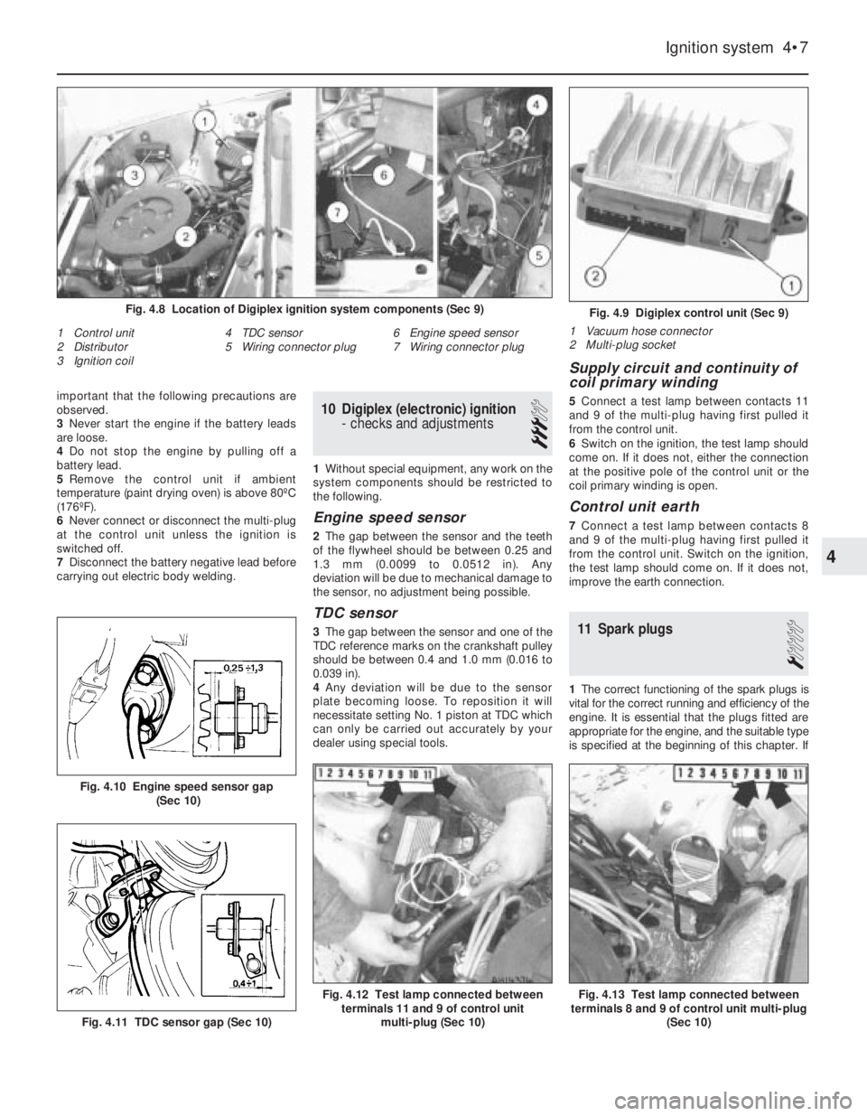
2The gap between the sensor and the teeth
of the flywheel should be between 0.25 and
1.3 mm (0.0099 to 0.0512 in). Any
deviation will be due to mechanical damage to
the sensor, no adjustment being possible.
TDC sensor
3The gap between the sensor and one of the
TDC reference marks on the crankshaft pulley
should be between 0.4 and 1.0 mm (0.016 to
0.039 in).
4Any deviation will be due to the sensor
plate becoming loose. To reposition it will
necessitate setting No. 1 piston at TDC which
can only be carried out accurately by your
dealer using special tools.
Supply circuit and continuity of
coil primary winding
5Connect a test lamp between contacts 11
and 9 of the multi-plug having first pulled it
from the control unit.
6Switch on the ignition, the test lamp should
come on. If it does not, either the connection
at the positive pole of the control unit or the
coil primary winding is open.
Control unit earth
7Connect a test lamp between contacts 8
and 9 of the multi-plug having first pulled it
from the control unit. Switch on the ignition,
the test lamp should come on. If it does not,
improve the earth connection.
11 Spark plugs
1
1The correct functioning of the spark plugs is
vital for the correct running and efficiency of the
engine. It is essential that the plugs fitted are
appropriate for the engine, and the suitable type
is specified at the beginning of this chapter. If
Ignition system 4•7
Fig. 4.9 Digiplex control unit (Sec 9)
1 Vacuum hose connector
2 Multi-plug socket
1 Control unit
2 Distributor
3 Ignition coil4 TDC sensor
5 Wiring connector plug6 Engine speed sensor
7 Wiring connector plug
Fig. 4.8 Location of Digiplex ignition system components (Sec 9)
Fig. 4.13 Test lamp connected between
terminals 8 and 9 of control unit multi-plug
(Sec 10)Fig. 4.12 Test lamp connected between
terminals 11 and 9 of control unit
multi-plug (Sec 10)
Fig. 4.11 TDC sensor gap (Sec 10)
Fig. 4.10 Engine speed sensor gap
(Sec 10)
4
Page 79 of 303
this type is used and the engine is in good
condition, the spark plugs should not need
attention between scheduled replacement
intervals. Spark plug cleaning is rarely
necessary and should not be attempted unless
specialised equipment is available as damage
can easily be caused to the firing ends.
2At the specified intervals, the plugs should
be renewed. The condition of the spark plug
will also tell much about the overall condition
of the engine.
3If the insulator nose of the spark plug is
clean and white, with no deposits, this is
indicative of a weak mixture, or too hot a plug.
(A hot plug transfers heat away from the
electrode slowly - a cold plug transfers it away
quickly.)
4If the tip of the insulator nose is covered
with sooty black deposits, then this is
indicative that the mixture is too rich. Should
the plug be black and oily, then it is likely that
the engine is fairly worn, as well as the mixture
being too rich.
5The spark plug gap is of considerable
importance, as, if it is too large or too small
the size of the spark and its efficiency will be
seriously impaired. The spark plug gap should
be set to the gap shown in the Specifications
for the best results.
6To set it, measure the gap with a feeler
gauge, and then bend open, or close, the
outer plug electrode until the correct gap is
achieved. The centre electrode should never
be bent as this may crack the insulation and
cause plug failure, if nothing worse.
7When fitting new plugs, check that the plug
seats in the cylinder head are quite clean.
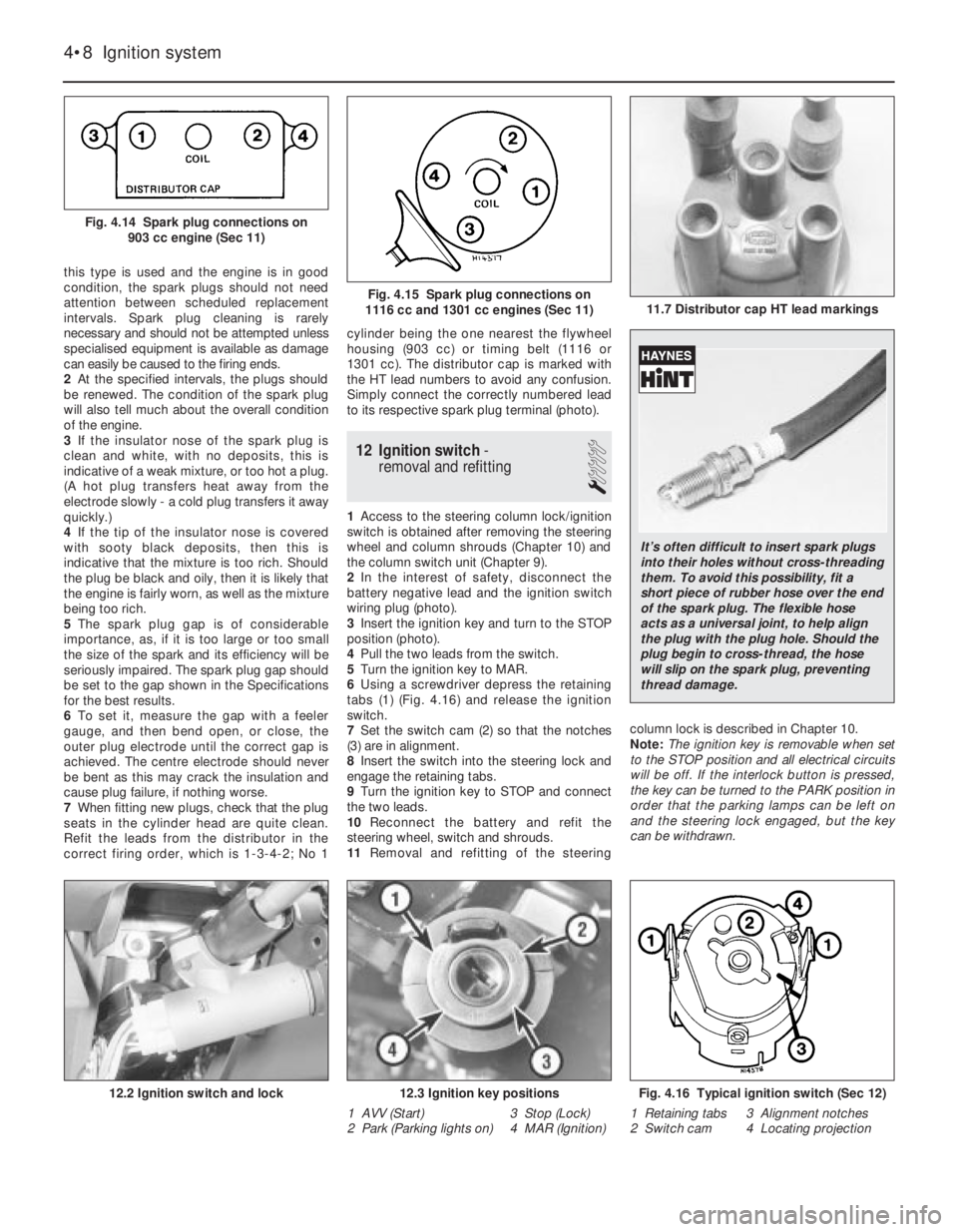
Refit the leads from the distributor in the
correct firing order, which is 1-3-4-2; No 1cylinder being the one nearest the flywheel
housing (903 cc) or timing belt (1116 or
1301 cc). The distributor cap is marked with
the HT lead numbers to avoid any confusion.
Simply connect the correctly numbered lead
to its respective spark plug terminal (photo).
12 Ignition switch-
removal and refitting
1
1Access to the steering column lock/ignition
switch is obtained after removing the steering
wheel and column shrouds (Chapter 10) and
the column switch unit (Chapter 9).
2In the interest of safety, disconnect the
battery negative lead and the ignition switch
wiring plug (photo).
3Insert the ignition key and turn to the STOP
position (photo).
4Pull the two leads from the switch.
5Turn the ignition key to MAR.
6Using a screwdriver depress the retaining
tabs (1) (Fig. 4.16) and release the ignition
switch.
7Set the switch cam (2) so that the notches
(3) are in alignment.
8Insert the switch into the steering lock and
engage the retaining tabs.
9Turn the ignition key to STOP and connect
the two leads.
10Reconnect the battery and refit the
steering wheel, switch and shrouds.
11Removal and refitting of the steeringcolumn lock is described in Chapter 10.
Note: The ignition key is removable when set
to the STOP position and all electrical circuits
will be off. If the interlock button is pressed,
the key can be turned to the PARK position in
order that the parking lamps can be left on
and the steering lock engaged, but the key
can be withdrawn.
4•8 Ignition system
Fig. 4.16 Typical ignition switch (Sec 12)
1 Retaining tabs 3 Alignment notches
2 Switch cam 4 Locating projection12.3 Ignition key positions
1 AVV (Start) 3 Stop (Lock)
2 Park (Parking lights on) 4 MAR (Ignition)12.2 Ignition switch and lock
11.7 Distributor cap HT lead markingsFig. 4.15 Spark plug connections on
1116 cc and 1301 cc engines (Sec 11)
Fig. 4.14 Spark plug connections on
903 cc engine (Sec 11)
It’s often difficult to insert spark plugs
into their holes without cross-threading
them. To avoid this possibility, fit a
short piece of rubber hose over the end
of the spark plug. The flexible hose
acts as a universal joint, to help align
the plug with the plug hole. Should the
plug begin to cross-thread, the hose
will slip on the spark plug, preventing
thread damage.
Page 91 of 303
1 General description
The electrical system is of 12 volt negative
earth type and employs a belt-driven
alternator and a pre-engaged type starter
motor.
The models in the range are all adequately
equipped with electrical accessories, while SX
versions also have power windows and
centralised door locking plus a check control
system (Section 34).
2 Battery- inspection, charging,
removal and refitting
2
1The battery is of maintenance-free type and
under normal circumstances, no topping up
will be required, but regularly check that the
electrolyte level is between the minimum and
maximum lines on the translucent battery
casing.
2If the electrolyte level does drop below theminimum line, suspect a leak in the battery
casing or that the alternator is overcharging. If
the latter is the case, rectify the alternator fault
and then prise out the two rectangular plugs
from the top of the battery and top up with
distilled or purified water.
3Always keep the battery terminals clean
and smear them with petroleum jelly to
prevent corrosion.
4The battery will normally be kept fully
charged by the alternator, but it is possible for
the battery to become discharged if the daily
mileage is very low with much use being
made of the starter and electrical accessories.
5When the battery begins to deteriorate with
age it may also require a boost from a mains
charger.
6Disconnect both battery leads before
connecting the mains charger. 7To remove the battery from the car, first
disconnect the leads from the battery
terminals (earth first) and then unscrew the
securing clamp from the casing projection at
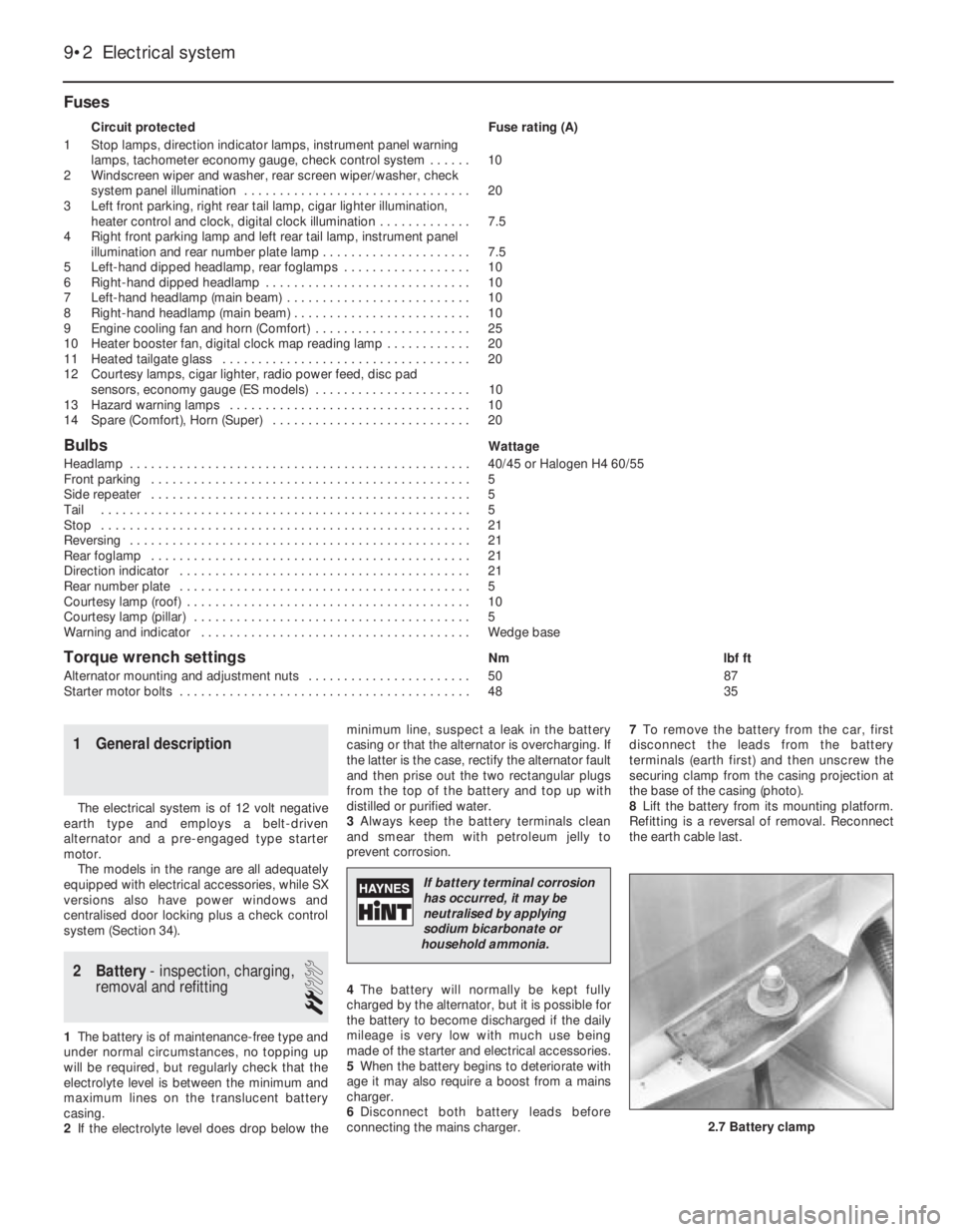
the base of the casing (photo).
8Lift the battery from its mounting platform.
Refitting is a reversal of removal. Reconnect
the earth cable last.
Fuses
Circuit protected Fuse rating (A)
1 Stop lamps, direction indicator lamps, instrument panel warning
lamps, tachometer economy gauge, check control system . . . . . . 10
2 Windscreen wiper and washer, rear screen wiper/washer, check
system panel illumination . . . . . . . . . . . . . . . . . . . . . . . . . . . . . . . . 20
3 Left front parking, right rear tail lamp, cigar lighter illumination,
heater control and clock, digital clock illumination . . . . . . . . . . . . . 7.5
4 Right front parking lamp and left rear tail lamp, instrument panel
illumination and rear number plate lamp . . . . . . . . . . . . . . . . . . . . . 7.5
5 Left-hand dipped headlamp, rear foglamps . . . . . . . . . . . . . . . . . . 10
6 Right-hand dipped headlamp . . . . . . . . . . . . . . . . . . . . . . . . . . . . . 10
7 Left-hand headlamp (main beam) . . . . . . . . . . . . . . . . . . . . . . . . . . 10
8 Right-hand headlamp (main beam) . . . . . . . . . . . . . . . . . . . . . . . . . 10
9 Engine cooling fan and horn (Comfort) . . . . . . . . . . . . . . . . . . . . . . 25
10 Heater booster fan, digital clock map reading lamp . . . . . . . . . . . . 20
11 Heated tailgate glass . . . . . . . . . . . . . . . . . . . . . . . . . . . . . . . . . . . 20
12 Courtesy lamps, cigar lighter, radio power feed, disc pad
sensors, economy gauge (ES models) . . . . . . . . . . . . . . . . . . . . . . 10
13 Hazard warning lamps . . . . . . . . . . . . . . . . . . . . . . . . . . . . . . . . . . 10
14 Spare (Comfort), Horn (Super) . . . . . . . . . . . . . . . . . . . . . . . . . . . . 20
BulbsWattage
Headlamp . . . . . . . . . . . . . . . . . . . . . . . . . . . . . . . . . . . . . . . . . . . . . . . . 40/45 or Halogen H4 60/55
Front parking . . . . . . . . . . . . . . . . . . . . . . . . . . . . . . . . . . . . . . . . . . . . . 5
Side repeater . . . . . . . . . . . . . . . . . . . . . . . . . . . . . . . . . . . . . . . . . . . . . 5
Tail . . . . . . . . . . . . . . . . . . . . . . . . . . . . . . . . . . . . . . . . . . . . . . . . . . . . 5
Stop . . . . . . . . . . . . . . . . . . . . . . . . . . . . . . . . . . . . . . . . . . . . . . . . . . . . 21
Reversing . . . . . . . . . . . . . . . . . . . . . . . . . . . . . . . . . . . . . . . . . . . . . . . . 21
Rear foglamp . . . . . . . . . . . . . . . . . . . . . . . . . . . . . . . . . . . . . . . . . . . . . 21
Direction indicator . . . . . . . . . . . . . . . . . . . . . . . . . . . . . . . . . . . . . . . . . 21
Rear number plate . . . . . . . . . . . . . . . . . . . . . . . . . . . . . . . . . . . . . . . . . 5
Courtesy lamp (roof) . . . . . . . . . . . . . . . . . . . . . . . . . . . . . . . . . . . . . . . . 10
Courtesy lamp (pillar) . . . . . . . . . . . . . . . . . . . . . . . . . . . . . . . . . . . . . . . 5
Warning and indicator . . . . . . . . . . . . . . . . . . . . . . . . . . . . . . . . . . . . . . Wedge base
Torque wrench settingsNm lbf ft
Alternator mounting and adjustment nuts . . . . . . . . . . . . . . . . . . . . . . . 50 87
Starter motor bolts . . . . . . . . . . . . . . . . . . . . . . . . . . . . . . . . . . . . . . . . . 48 35
9•2 Electrical system
2.7 Battery clamp
If battery terminal corrosion
has occurred, it may be
neutralised by applying
sodium bicarbonate or
household ammonia.
Page 92 of 303
3 Alternator-
maintenance and precautions
1
To avoid damage to the alternator, the
following precautions should be observed.
1Disconnect the leads from the battery
before connecting a mains charger to the
battery terminals.
2Never stop the engine by pulling off one of
the battery leads.
3Disconnect the battery if electric welding is
to be carried out on the vehicle.
4If using booster cables from another battery
to start the car, make sure that they are
connected positive to positive and negative to
negative.
5Maintenance consists of keeping the
outside of the alternator clean, the electrical
connections secure and the drivebelt correctly
tensioned, see Chapter 2, Section 8.
4 Alternator-
removal and refitting
1
Note: Depending on the model, access to the
alternator from above may be poor in which
case it will be necessary to work from the
underside of the vehicle, through the
right-hand wheel arch (after removing the
roadwheel and the lower undershield). Refer
to Chapter 13 for details.
1Disconnect the leads from the rear of the
alternator.2Release the mounting and adjuster link nuts
and push the alternator as far as it will go in
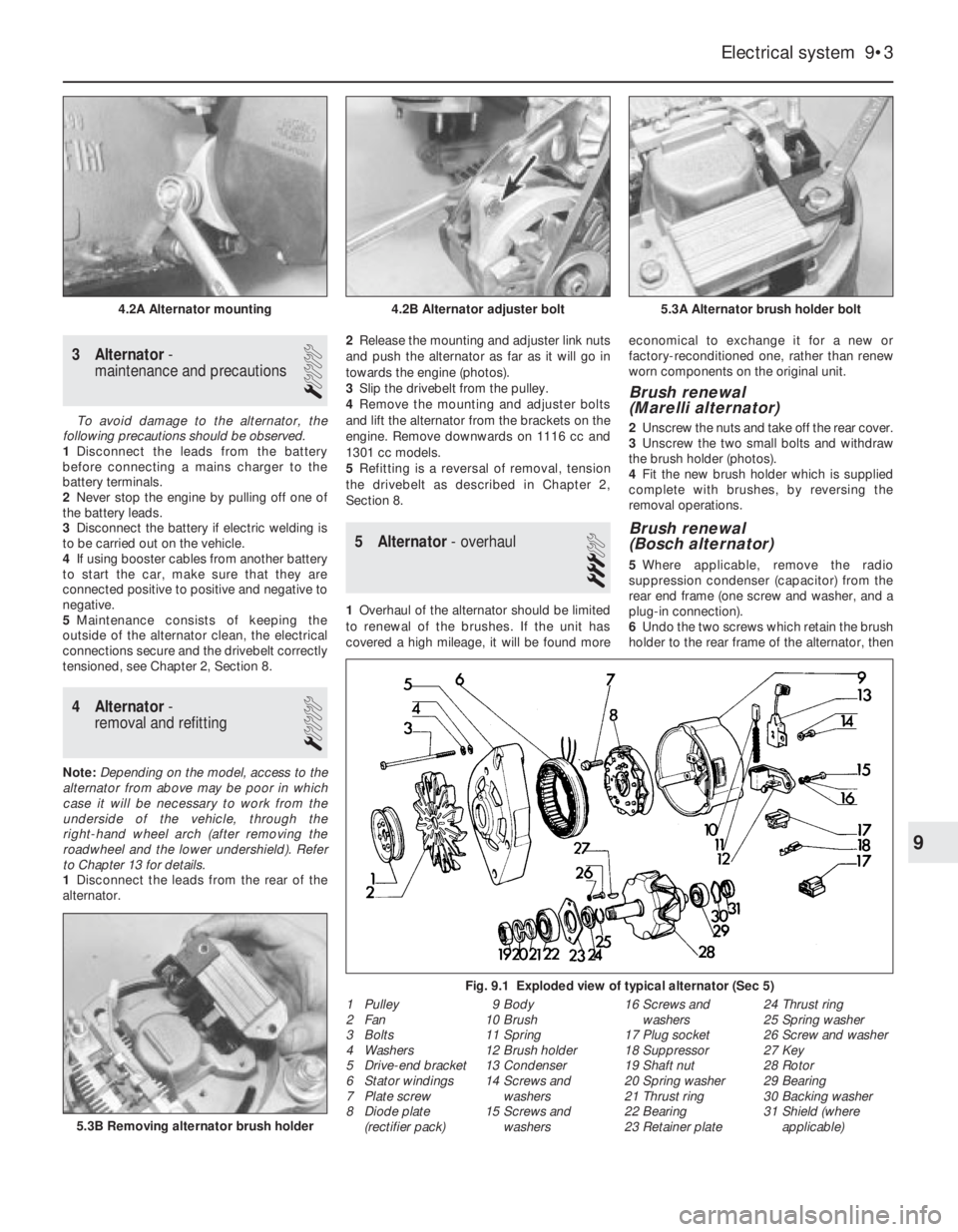
towards the engine (photos).
3Slip the drivebelt from the pulley.
4Remove the mounting and adjuster bolts
and lift the alternator from the brackets on the
engine. Remove downwards on 1116 cc and
1301 cc models.
5Refitting is a reversal of removal, tension
the drivebelt as described in Chapter 2,
Section 8.
5 Alternator- overhaul
3
1Overhaul of the alternator should be limited
to renewal of the brushes. If the unit has
covered a high mileage, it will be found moreeconomical to exchange it for a new or
factory-reconditioned one, rather than renew
worn components on the original unit.
Brush renewal
(Marelli alternator)
2Unscrew the nuts and take off the rear cover.
3Unscrew the two small bolts and withdraw
the brush holder (photos).
4Fit the new brush holder which is supplied
complete with brushes, by reversing the
removal operations.
Brush renewal
(Bosch alternator)
5Where applicable, remove the radio
suppression condenser (capacitor) from the
rear end frame (one screw and washer, and a
plug-in connection).
6Undo the two screws which retain the brush
holder to the rear frame of the alternator, then
Electrical system 9•3
5.3A Alternator brush holder bolt4.2B Alternator adjuster bolt4.2A Alternator mounting
Fig. 9.1 Exploded view of typical alternator (Sec 5)
1 Pulley
2 Fan
3 Bolts
4 Washers
5 Drive-end bracket
6 Stator windings
7 Plate screw
8 Diode plate
(rectifier pack)9 Body
10 Brush
11 Spring
12 Brush holder
13 Condenser
14 Screws and
washers
15 Screws and
washers16 Screws and
washers
17 Plug socket
18 Suppressor
19 Shaft nut
20 Spring washer
21 Thrust ring
22 Bearing
23 Retainer plate24 Thrust ring
25 Spring washer
26 Screw and washer
27 Key
28 Rotor
29 Bearing
30 Backing washer
31 Shield (where
applicable)
5.3B Removing alternator brush holder
9