fuel pressure FIAT UNO 1983 Service Repair Manual
[x] Cancel search | Manufacturer: FIAT, Model Year: 1983, Model line: UNO, Model: FIAT UNO 1983Pages: 303, PDF Size: 10.36 MB
Page 5 of 303
Safety First!0•5
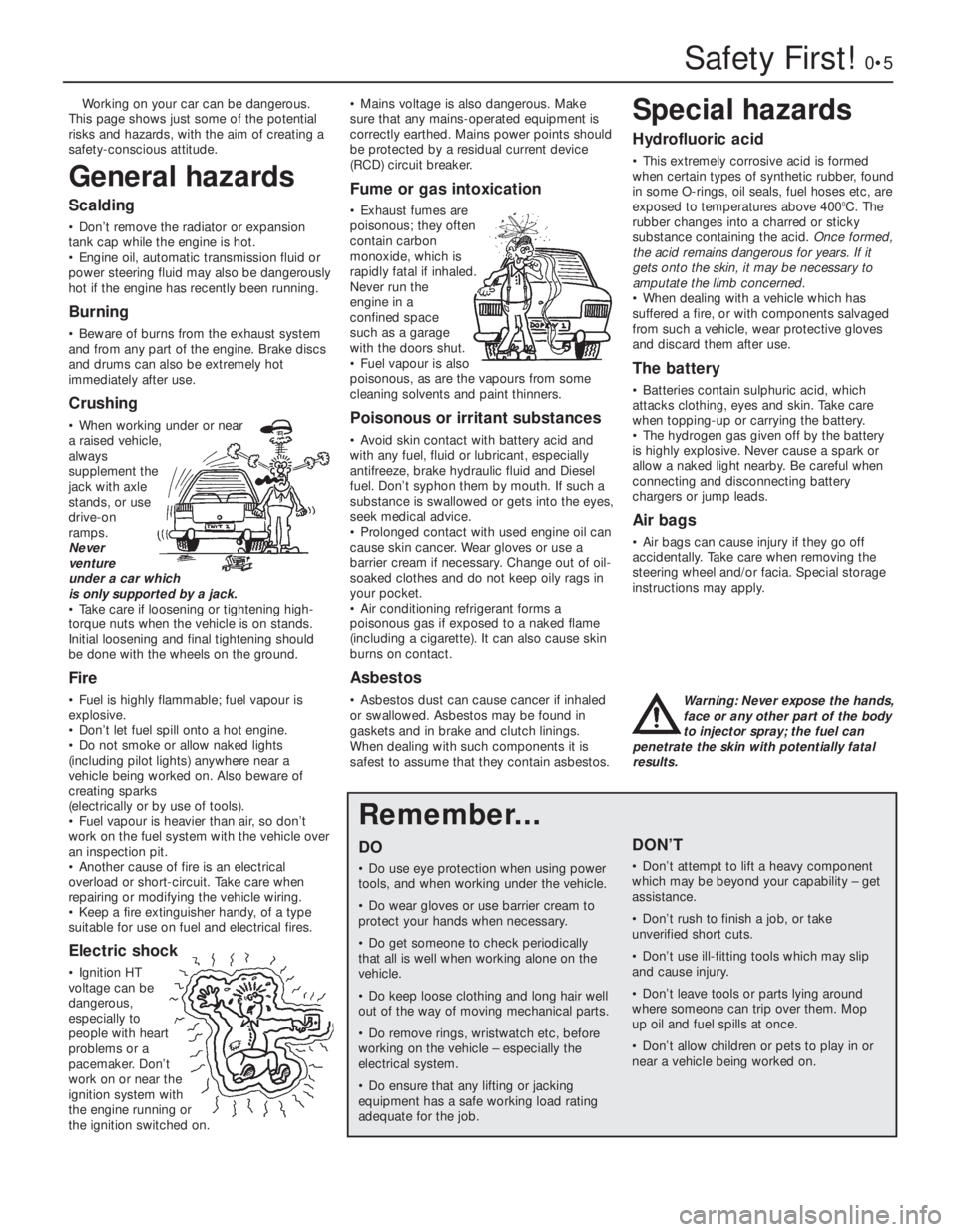
Working on your car can be dangerous.
This page shows just some of the potential
risks and hazards, with the aim of creating a
safety-conscious attitude.
General hazards
Scalding
• Don’t remove the radiator or expansion
tank cap while the engine is hot.
• Engine oil, automatic transmission fluid or
power steering fluid may also be dangerously
hot if the engine has recently been running.
Burning
• Beware of burns from the exhaust system
and from any part of the engine. Brake discs
and drums can also be extremely hot
immediately after use.
Crushing
• When working under or near
a raised vehicle,
always
supplement the
jack with axle
stands, or use
drive-on
ramps.
Never
venture
under a car which
is only supported by a jack.
• Take care if loosening or tightening high-
torque nuts when the vehicle is on stands.
Initial loosening and final tightening should
be done with the wheels on the ground.
Fire
• Fuel is highly flammable; fuel vapour is
explosive.
• Don’t let fuel spill onto a hot engine.
• Do not smoke or allow naked lights
(including pilot lights) anywhere near a
vehicle being worked on. Also beware of
creating sparks
(electrically or by use of tools).
• Fuel vapour is heavier than air, so don’t
work on the fuel system with the vehicle over
an inspection pit.
• Another cause of fire is an electrical
overload or short-circuit. Take care when
repairing or modifying the vehicle wiring.
• Keep a fire extinguisher handy, of a type
suitable for use on fuel and electrical fires.
Electric shock
• Ignition HT
voltage can be
dangerous,
especially to
people with heart
problems or a
pacemaker. Don’t
work on or near the
ignition system with
the engine running or
the ignition switched on.• Mains voltage is also dangerous. Make
sure that any mains-operated equipment is
correctly earthed. Mains power points should
be protected by a residual current device
(RCD) circuit breaker.
Fume or gas intoxication
• Exhaust fumes are
poisonous; they often
contain carbon
monoxide, which is
rapidly fatal if inhaled.
Never run the
engine in a
confined space
such as a garage
with the doors shut.
• Fuel vapour is also
poisonous, as are the vapours from some
cleaning solvents and paint thinners.
Poisonous or irritant substances
• Avoid skin contact with battery acid and
with any fuel, fluid or lubricant, especially
antifreeze, brake hydraulic fluid and Diesel
fuel. Don’t syphon them by mouth. If such a
substance is swallowed or gets into the eyes,
seek medical advice.
• Prolonged contact with used engine oil can
cause skin cancer. Wear gloves or use a
barrier cream if necessary. Change out of oil-
soaked clothes and do not keep oily rags in
your pocket.
• Air conditioning refrigerant forms a
poisonous gas if exposed to a naked flame
(including a cigarette). It can also cause skin
burns on contact.
Asbestos
• Asbestos dust can cause cancer if inhaled
or swallowed. Asbestos may be found in
gaskets and in brake and clutch linings.
When dealing with such components it is
safest to assume that they contain asbestos.
Special hazards
Hydrofluoric acid
• This extremely corrosive acid is formed
when certain types of synthetic rubber, found
in some O-rings, oil seals, fuel hoses etc, are
exposed to temperatures above 400
0C. The
rubber changes into a charred or sticky
substance containing the acid. Once formed,
the acid remains dangerous for years. If it
gets onto the skin, it may be necessary to
amputate the limb concerned.
• When dealing with a vehicle which has
suffered a fire, or with components salvaged
from such a vehicle, wear protective gloves
and discard them after use.
The battery
• Batteries contain sulphuric acid, which
attacks clothing, eyes and skin. Take care
when topping-up or carrying the battery.
• The hydrogen gas given off by the battery
is highly explosive. Never cause a spark or
allow a naked light nearby. Be careful when
connecting and disconnecting battery
chargers or jump leads.
Air bags
• Air bags can cause injury if they go off
accidentally. Take care when removing the
steering wheel and/or facia. Special storage
instructions may apply.
Diesel injection equipment
• Diesel injection pumps supply fuel at very
high pressure. Take care when working on
the fuel injectors and fuel pipes.
Warning: Never expose the hands,
face or any other part of the body
to injector spray; the fuel can
penetrate the skin with potentially fatal
results.
Remember...
DO
• Do use eye protection when using power
tools, and when working under the vehicle.
• Do wear gloves or use barrier cream to
protect your hands when necessary.
• Do get someone to check periodically
that all is well when working alone on the
vehicle.
• Do keep loose clothing and long hair well
out of the way of moving mechanical parts.
• Do remove rings, wristwatch etc, before
working on the vehicle – especially the
electrical system.
• Do ensure that any lifting or jacking
equipment has a safe working load rating
adequate for the job.
A few tips
DON’T
• Don’t attempt to lift a heavy component
which may be beyond your capability – get
assistance.
• Don’t rush to finish a job, or take
unverified short cuts.
• Don’t use ill-fitting tools which may slip
and cause injury.
• Don’t leave tools or parts lying around
where someone can trip over them. Mop
up oil and fuel spills at once.
• Don’t allow children or pets to play in or
near a vehicle being worked on.
Page 14 of 303

0•14Conversion Factors
Length (distance)
Inches (in) x 25.4 = Millimetres (mm) x 0.0394 = Inches (in)
Feet (ft) x 0.305 = Metres (m) x 3.281 = Feet (ft)
Miles x 1.609 = Kilometres (km) x 0.621 = Miles
Volume (capacity)
Cubic inches (cu in; in3) x 16.387 = Cubic centimetres (cc; cm3) x 0.061 = Cubic inches (cu in; in3)
Imperial pints (Imp pt) x 0.568 = Litres (l) x 1.76 = Imperial pints (Imp pt)
Imperial quarts (Imp qt) x 1.137 = Litres (l) x 0.88 = Imperial quarts (Imp qt)
Imperial quarts (Imp qt) x 1.201 = US quarts (US qt) x 0.833 = Imperial quarts (Imp qt)
US quarts (US qt) x 0.946 = Litres (l) x 1.057 = US quarts (US qt)
Imperial gallons (Imp gal) x 4.546 = Litres (l) x 0.22 = Imperial gallons (Imp gal)
Imperial gallons (Imp gal) x 1.201 = US gallons (US gal) x 0.833 = Imperial gallons (Imp gal)
US gallons (US gal) x 3.785 = Litres (l) x 0.264 = US gallons (US gal)
Mass (weight)
Ounces (oz) x 28.35 = Grams (g) x 0.035 = Ounces (oz)
Pounds (lb) x 0.454 = Kilograms (kg) x 2.205 = Pounds (lb)
Force
Ounces-force (ozf; oz) x 0.278 = Newtons (N) x 3.6 = Ounces-force (ozf; oz)
Pounds-force (lbf; lb) x 4.448 = Newtons (N) x 0.225 = Pounds-force (lbf; lb)
Newtons (N) x 0.1 = Kilograms-force (kgf; kg) x 9.81 = Newtons (N)
Pressure
Pounds-force per square inch x 0.070 = Kilograms-force per square x 14.223 = Pounds-force per square inch
(psi; lbf/in2; lb/in2) centimetre (kgf/cm2; kg/cm2) (psi; lbf/in2; lb/in2)
Pounds-force per square inch x 0.068 = Atmospheres (atm) x 14.696 = Pounds-force per square inch
(psi; lbf/in
2; lb/in2)(psi; lbf/in2; lb/in2)
Pounds-force per square inch x 0.069 = Bars x 14.5 = Pounds-force per square inch
(psi; lbf/in
2; lb/in2)(psi; lbf/in2; lb/in2)
Pounds-force per square inch x 6.895 = Kilopascals (kPa) x 0.145 = Pounds-force per square inch
(psi; lbf/in
2; lb/in2)(psi; lbf/in2; lb/in2)
Kilopascals (kPa) x 0.01 = Kilograms-force per square x 98.1 = Kilopascals (kPa)
centimetre (kgf/cm
2; kg/cm2)
Millibar (mbar) x 100 = Pascals (Pa) x 0.01 = Millibar (mbar)
Millibar (mbar) x 0.0145 = Pounds-force per square inch x 68.947 = Millibar (mbar)
(psi; lbf/in
2; lb/in2)
Millibar (mbar) x 0.75 = Millimetres of mercury (mmHg) x 1.333 = Millibar (mbar)
Millibar (mbar) x 0.401 = Inches of water (inH
2O) x 2.491 = Millibar (mbar)
Millimetres of mercury (mmHg) x 0.535 = Inches of water (inH
2O) x 1.868 = Millimetres of mercury (mmHg)
Inches of water (inH
2O) x 0.036 = Pounds-force per square inch x 27.68 = Inches of water (inH2O)
(psi; lbf/in2; lb/in2)
Torque (moment of force)
Pounds-force inches x 1.152 = Kilograms-force centimetre x 0.868 = Pounds-force inches
(lbf in; lb in) (kgf cm; kg cm) (lbf in; lb in)
Pounds-force inches x 0.113 = Newton metres (Nm) x 8.85 = Pounds-force inches
(lbf in; lb in)(lbf in; lb in)
Pounds-force inches x 0.083 = Pounds-force feet (lbf ft; lb ft) x 12 = Pounds-force inches
(lbf in; lb in)(lbf in; lb in)
Pounds-force feet (lbf ft; lb ft) x 0.138 = Kilograms-force metres x 7.233 = Pounds-force feet (lbf ft; lb ft)
(kgf m; kg m)
Pounds-force feet (lbf ft; lb ft) x 1.356 = Newton metres (Nm) x 0.738 = Pounds-force feet (lbf ft; lb ft)
Newton metres (Nm) x 0.102 = Kilograms-force metres x 9.804 = Newton metres (Nm)
(kgf m; kg m)
Power
Horsepower (hp) x 745.7 = Watts (W) x 0.0013 = Horsepower (hp)
Velocity (speed)
Miles per hour (miles/hr; mph) x 1.609 = Kilometres per hour (km/hr; kph) x 0.621 = Miles per hour (miles/hr; mph)
Fuel consumption*
Miles per gallon (mpg) x 0.354 = Kilometres per litre (km/l) x 2.825 = Miles per gallon (mpg)
Temperature
Degrees Fahrenheit = (°C x 1.8) + 32 Degrees Celsius (Degrees Centigrade; °C) = (°F - 32) x 0.56
* It is common practice to convert from miles per gallon (mpg) to litres/100 kilometres (l/100km), where mpg x l/100 km = 282
Page 20 of 303
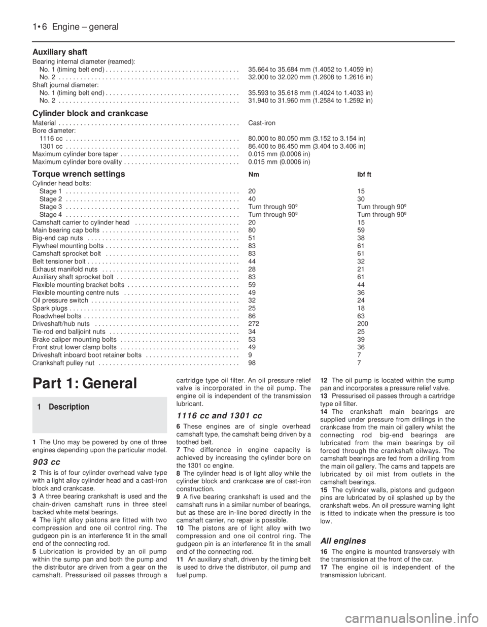
Auxiliary shaft
Bearing internal diameter (reamed):
No. 1 (timing belt end) . . . . . . . . . . . . . . . . . . . . . . . . . . . . . . . . . . . . . 35.664 to 35.684 mm (1.4052 to 1.4059 in)
No. 2 . . . . . . . . . . . . . . . . . . . . . . . . . . . . . . . . . . . . . . . . . . . . . . . . . . 32.000 to 32.020 mm (1.2608 to 1.2616 in)
Shaft journal diameter:
No. 1 (timing belt end) . . . . . . . . . . . . . . . . . . . . . . . . . . . . . . . . . . . . . 35.593 to 35.618 mm (1.4024 to 1.4033 in)
No. 2 . . . . . . . . . . . . . . . . . . . . . . . . . . . . . . . . . . . . . . . . . . . . . . . . . . 31.940 to 31.960 mm (1.2584 to 1.2592 in)
Cylinder block and crankcase
Material . . . . . . . . . . . . . . . . . . . . . . . . . . . . . . . . . . . . . . . . . . . . . . . . . . Cast-iron
Bore diameter:
1116 cc . . . . . . . . . . . . . . . . . . . . . . . . . . . . . . . . . . . . . . . . . . . . . . . . 80.000 to 80.050 mm (3.152 to 3.154 in)
1301 cc . . . . . . . . . . . . . . . . . . . . . . . . . . . . . . . . . . . . . . . . . . . . . . . . 86.400 to 86.450 mm (3.404 to 3.406 in)
Maximum cylinder bore taper . . . . . . . . . . . . . . . . . . . . . . . . . . . . . . . . . 0.015 mm (0.0006 in)
Maximum cylinder bore ovality . . . . . . . . . . . . . . . . . . . . . . . . . . . . . . . . 0.015 mm (0.0006 in)
Torque wrench settingsNm lbf ft
Cylinder head bolts:
Stage 1 . . . . . . . . . . . . . . . . . . . . . . . . . . . . . . . . . . . . . . . . . . . . . . . . 20 15
Stage 2 . . . . . . . . . . . . . . . . . . . . . . . . . . . . . . . . . . . . . . . . . . . . . . . . 40 30
Stage 3 . . . . . . . . . . . . . . . . . . . . . . . . . . . . . . . . . . . . . . . . . . . . . . . . Turn through 90º Turn through 90º
Stage 4 . . . . . . . . . . . . . . . . . . . . . . . . . . . . . . . . . . . . . . . . . . . . . . . . Turn through 90º Turn through 90º
Camshaft carrier to cylinder head . . . . . . . . . . . . . . . . . . . . . . . . . . . . . 20 15
Main bearing cap bolts . . . . . . . . . . . . . . . . . . . . . . . . . . . . . . . . . . . . . . 80 59
Big-end cap nuts . . . . . . . . . . . . . . . . . . . . . . . . . . . . . . . . . . . . . . . . . . 51 38
Flywheel mounting bolts . . . . . . . . . . . . . . . . . . . . . . . . . . . . . . . . . . . . . 83 61
Camshaft sprocket bolt . . . . . . . . . . . . . . . . . . . . . . . . . . . . . . . . . . . . . 83 61
Belt tensioner bolt . . . . . . . . . . . . . . . . . . . . . . . . . . . . . . . . . . . . . . . . . . 44 32
Exhaust manifold nuts . . . . . . . . . . . . . . . . . . . . . . . . . . . . . . . . . . . . . . 28 21
Auxiliary shaft sprocket bolt . . . . . . . . . . . . . . . . . . . . . . . . . . . . . . . . . . 83 61
Flexible mounting bracket bolts . . . . . . . . . . . . . . . . . . . . . . . . . . . . . . . 59 44
Flexible mounting centre nuts . . . . . . . . . . . . . . . . . . . . . . . . . . . . . . . . 49 36
Oil pressure switch . . . . . . . . . . . . . . . . . . . . . . . . . . . . . . . . . . . . . . . . . 32 24
Spark plugs . . . . . . . . . . . . . . . . . . . . . . . . . . . . . . . . . . . . . . . . . . . . . . . 25 18
Roadwheel bolts . . . . . . . . . . . . . . . . . . . . . . . . . . . . . . . . . . . . . . . . . . . 86 63
Driveshaft/hub nuts . . . . . . . . . . . . . . . . . . . . . . . . . . . . . . . . . . . . . . . . 272 200
Tie-rod end balljoint nuts . . . . . . . . . . . . . . . . . . . . . . . . . . . . . . . . . . . . 34 25
Brake caliper mounting bolts . . . . . . . . . . . . . . . . . . . . . . . . . . . . . . . . . 53 39
Front strut lower clamp bolts . . . . . . . . . . . . . . . . . . . . . . . . . . . . . . . . . 49 36
Driveshaft inboard boot retainer bolts . . . . . . . . . . . . . . . . . . . . . . . . . . 9 7
Crankshaft pulley nut . . . . . . . . . . . . . . . . . . . . . . . . . . . . . . . . . . . . . . . 98 7
1•6 Engine – general
Part 1: General
1 Description
1The Uno may be powered by one of three
engines depending upon the particular model.
903 cc
2This is of four cylinder overhead valve type
with a light alloy cylinder head and a cast-iron
block and crankcase.
3A three bearing crankshaft is used and the
chain-driven camshaft runs in three steel
backed white metal bearings.
4The light alloy pistons are fitted with two
compression and one oil control ring. The
gudgeon pin is an interference fit in the small
end of the connecting rod.
5Lubrication is provided by an oil pump
within the sump pan and both the pump and
the distributor are driven from a gear on the
camshaft. Pressurised oil passes through acartridge type oil filter. An oil pressure relief
valve is incorporated in the oil pump. The
engine oil is independent of the transmission
lubricant.
1116 cc and 1301 cc
6These engines are of single overhead
camshaft type, the camshaft being driven by a
toothed belt.
7The difference in engine capacity is
achieved by increasing the cylinder bore on
the 1301 cc engine.
8The cylinder head is of light alloy while the
cylinder block and crankcase are of cast-iron
construction.
9A five bearing crankshaft is used and the
camshaft runs in a similar number of bearings,
but as these are in-line bored directly in the
camshaft carrier, no repair is possible.
10The pistons are of light alloy with two
compression and one oil control ring. The
gudgeon pin is an interference fit in the small
end of the connecting rod.
11An auxiliary shaft, driven by the timing belt
is used to drive the distributor, oil pump and
fuel pump.12The oil pump is located within the sump
pan and incorporates a pressure relief valve.
13Pressurised oil passes through a cartridge
type oil filter.
14The crankshaft main bearings are
supplied under pressure from drillings in the
crankcase from the main oil gallery whilst the
connecting rod big-end bearings are
lubricated from the main bearings by oil
forced through the crankshaft oilways. The
camshaft bearings are fed from a drilling from
the main oil gallery. The cams and tappets are
lubricated by oil mist from outlets in the
camshaft bearings.
15The cylinder walls, pistons and gudgeon
pins are lubricated by oil splashed up by the
crankshaft webs. An oil pressure warning light
is fitted to indicate when the pressure is too
low.
All engines
16The engine is mounted transversely with
the transmission at the front of the car.
17The engine oil is independent of the
transmission lubricant.
Page 41 of 303
2The big-end bearing shells can be renewed
without having to remove the cylinder head if
the caps are unbolted and the
piston/connecting rod pushed gently about
one inch up the bore (the crankpin being at its
lowest point). If these shells are worn,
however, the main bearing shells will almost
certainly be worn as well. In this case, the
engine should be removed for complete
overhaul including crankshaft removal.
3To remove the piston/connecting rods,
remove the cylinder head as described in
Section 29.
4Grip the oil pick-up pipe and twist or rock it
from its hole in the crankcase. It is an
interference fit in the hole.
5Unscrew the nuts from the big-end caps,
then remove the caps with their bearing
shells. The caps and their connecting rods are
numbered 1, 2, 3 and 4 from the timing cover
end of the engine. The numbers are adjacent
at the big-end cap joint and on the side of the
crankcase furthest from the auxiliary shaft.
6If the bearing shells are to be used again,
tape them to their respective big-end caps.
7Push each connecting rod/piston assembly
up the bore and out of the cylinder block.
There is one reservation; if a wear ridge has
developed at the top of the bores, remove this
by careful scraping before trying to remove
the piston/rod assemblies. The ridge will
otherwise prevent removal or break the piston
rings during the attempt.
8If the connecting rod bearing shells are to
be used again, tape the shells to their
respective rods.
9Dismantling the piston/connecting rod is
described in Section 18.
Refitting
10Fit the new shells into the connecting rod
and caps, ensuring the surfaces on which the
shells seat, are clean and dry.
11Check that the piston ring gaps are evenly
spaced at 120º intervals. Liberally oil the rings
and the cylinder bores.
12Fit a piston ring clamp to compress the
rings.
13Insert the piston/connecting rod into the
cylinder bore, checking that the rod assembly
is correct for that particular bore. The cap and
rod matching numbers must be furthest away
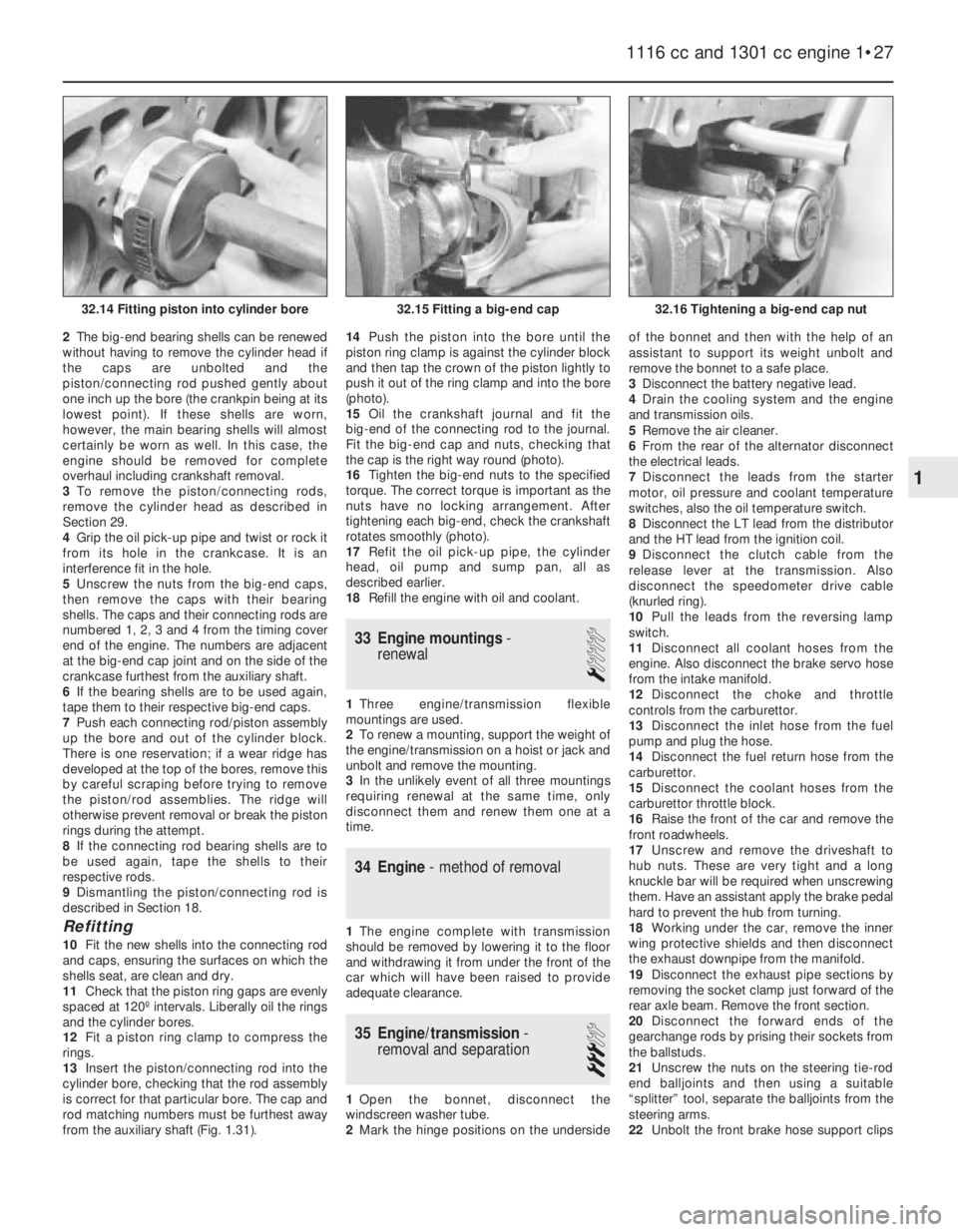
from the auxiliary shaft (Fig. 1.31).14Push the piston into the bore until the
piston ring clamp is against the cylinder block
and then tap the crown of the piston lightly to
push it out of the ring clamp and into the bore
(photo).
15Oil the crankshaft journal and fit the
big-end of the connecting rod to the journal.
Fit the big-end cap and nuts, checking that
the cap is the right way round (photo).
16Tighten the big-end nuts to the specified
torque. The correct torque is important as the
nuts have no locking arrangement. After
tightening each big-end, check the crankshaft
rotates smoothly (photo).
17Refit the oil pick-up pipe, the cylinder
head, oil pump and sump pan, all as
described earlier.
18Refill the engine with oil and coolant.
33 Engine mountings-
renewal
1
1Three engine/transmission flexible
mountings are used.
2To renew a mounting, support the weight of
the engine/transmission on a hoist or jack and
unbolt and remove the mounting.
3In the unlikely event of all three mountings
requiring renewal at the same time, only
disconnect them and renew them one at a
time.
34 Engine- method of removal
1The engine complete with transmission
should be removed by lowering it to the floor
and withdrawing it from under the front of the
car which will have been raised to provide
adequate clearance.
35 Engine/transmission-
removal and separation
3
1Open the bonnet, disconnect the
windscreen washer tube.
2Mark the hinge positions on the undersideof the bonnet and then with the help of an
assistant to support its weight unbolt and
remove the bonnet to a safe place.
3Disconnect the battery negative lead.
4Drain the cooling system and the engine
and transmission oils.
5Remove the air cleaner.
6From the rear of the alternator disconnect
the electrical leads.
7Disconnect the leads from the starter
motor, oil pressure and coolant temperature
switches, also the oil temperature switch.
8Disconnect the LT lead from the distributor
and the HT lead from the ignition coil.
9Disconnect the clutch cable from the
release lever at the transmission. Also
disconnect the speedometer drive cable
(knurled ring).
10Pull the leads from the reversing lamp
switch.
11Disconnect all coolant hoses from the
engine. Also disconnect the brake servo hose
from the intake manifold.
12Disconnect the choke and throttle
controls from the carburettor.
13Disconnect the inlet hose from the fuel
pump and plug the hose.
14Disconnect the fuel return hose from the
carburettor.
15Disconnect the coolant hoses from the
carburettor throttle block.
16Raise the front of the car and remove the
front roadwheels.
17Unscrew and remove the driveshaft to
hub nuts. These are very tight and a long
knuckle bar will be required when unscrewing
them. Have an assistant apply the brake pedal
hard to prevent the hub from turning.
18Working under the car, remove the inner
wing protective shields and then disconnect
the exhaust downpipe from the manifold.
19Disconnect the exhaust pipe sections by
removing the socket clamp just forward of the
rear axle beam. Remove the front section.
20Disconnect the forward ends of the
gearchange rods by prising their sockets from
the ballstuds.
21Unscrew the nuts on the steering tie-rod
end balljoints and then using a suitable
“splitter” tool, separate the balljoints from the
steering arms.
22Unbolt the front brake hose support clips
1116 cc and 1301 cc engine 1•27
32.16 Tightening a big-end cap nut32.15 Fitting a big-end cap32.14 Fitting piston into cylinder bore
1
Page 43 of 303
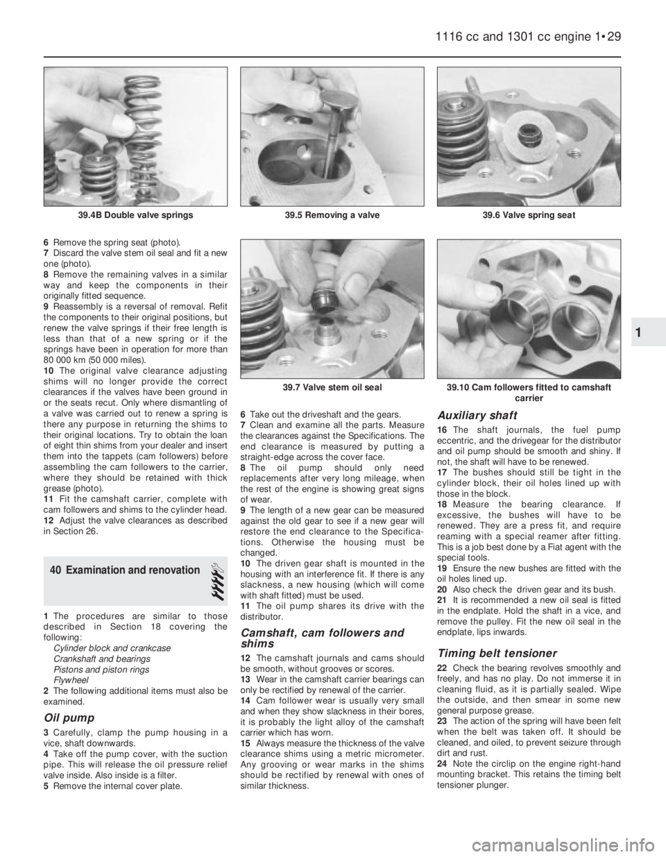
6Remove the spring seat (photo).
7Discard the valve stem oil seal and fit a new
one (photo).
8Remove the remaining valves in a similar
way and keep the components in their
originally fitted sequence.
9Reassembly is a reversal of removal. Refit
the components to their original positions, but
renew the valve springs if their free length is
less than that of a new spring or if the
springs have been in operation for more than
80 000 km (50 000 miles).
10The original valve clearance adjusting
shims will no longer provide the correct
clearances if the valves have been ground in
or the seats recut. Only where dismantling of
a valve was carried out to renew a spring is
there any purpose in returning the shims to
their original locations. Try to obtain the loan
of eight thin shims from your dealer and insert
them into the tappets (cam followers) before
assembling the cam followers to the carrier,
where they should be retained with thick
grease (photo).
11Fit the camshaft carrier, complete with
cam followers and shims to the cylinder head.
12Adjust the valve clearances as described
in Section 26.
40 Examination and renovation
4
1The procedures are similar to those
described in Section 18 covering the
following:
Cylinder block and crankcase
Crankshaft and bearings
Pistons and piston rings
Flywheel
2The following additional items must also be
examined.
Oil pump
3Carefully, clamp the pump housing in a
vice, shaft downwards.
4Take off the pump cover, with the suction
pipe. This will release the oil pressure relief
valve inside. Also inside is a filter.
5Remove the internal cover plate.6Take out the driveshaft and the gears.
7Clean and examine all the parts. Measure
the clearances against the Specifications. The
end clearance is measured by putting a
straight-edge across the cover face.
8The oil pump should only need
replacements after very long mileage, when
the rest of the engine is showing great signs
of wear.
9The length of a new gear can be measured
against the old gear to see if a new gear will
restore the end clearance to the Specifica-
tions. Otherwise the housing must be
changed.
10The driven gear shaft is mounted in the
housing with an interference fit. If there is any
slackness, a new housing (which will come
with shaft fitted) must be used.
11The oil pump shares its drive with the
distributor.
Camshaft, cam followers and
shims
12The camshaft journals and cams should
be smooth, without grooves or scores.
13Wear in the camshaft carrier bearings can
only be rectified by renewal of the carrier.
14Cam follower wear is usually very small
and when they show slackness in their bores,
it is probably the light alloy of the camshaft
carrier which has worn.
15Always measure the thickness of the valve
clearance shims using a metric micrometer.
Any grooving or wear marks in the shims
should be rectified by renewal with ones of
similar thickness.
Auxiliary shaft
16The shaft journals, the fuel pump
eccentric, and the drivegear for the distributor
and oil pump should be smooth and shiny. If
not, the shaft will have to be renewed.
17The bushes should still be tight in the
cylinder block, their oil holes lined up with
those in the block.
18Measure the bearing clearance. If
excessive, the bushes will have to be
renewed. They are a press fit, and require
reaming with a special reamer after fitting.
This is a job best done by a Fiat agent with the
special tools.
19Ensure the new bushes are fitted with the
oil holes lined up.
20Also check the driven gear and its bush.
21It is recommended a new oil seal is fitted
in the endplate. Hold the shaft in a vice, and
remove the pulley. Fit the new oil seal in the
endplate, lips inwards.
Timing belt tensioner
22Check the bearing revolves smoothly and
freely, and has no play. Do not immerse it in
cleaning fluid, as it is partially sealed. Wipe
the outside, and then smear in some new
general purpose grease.
23The action of the spring will have been felt
when the belt was taken off. It should be
cleaned, and oiled, to prevent seizure through
dirt and rust.
24Note the circlip on the engine right-hand
mounting bracket. This retains the timing belt
tensioner plunger.
1116 cc and 1301 cc engine 1•29
39.6 Valve spring seat39.5 Removing a valve39.4B Double valve springs
39.10 Cam followers fitted to camshaft
carrier39.7 Valve stem oil seal
1
Page 46 of 303
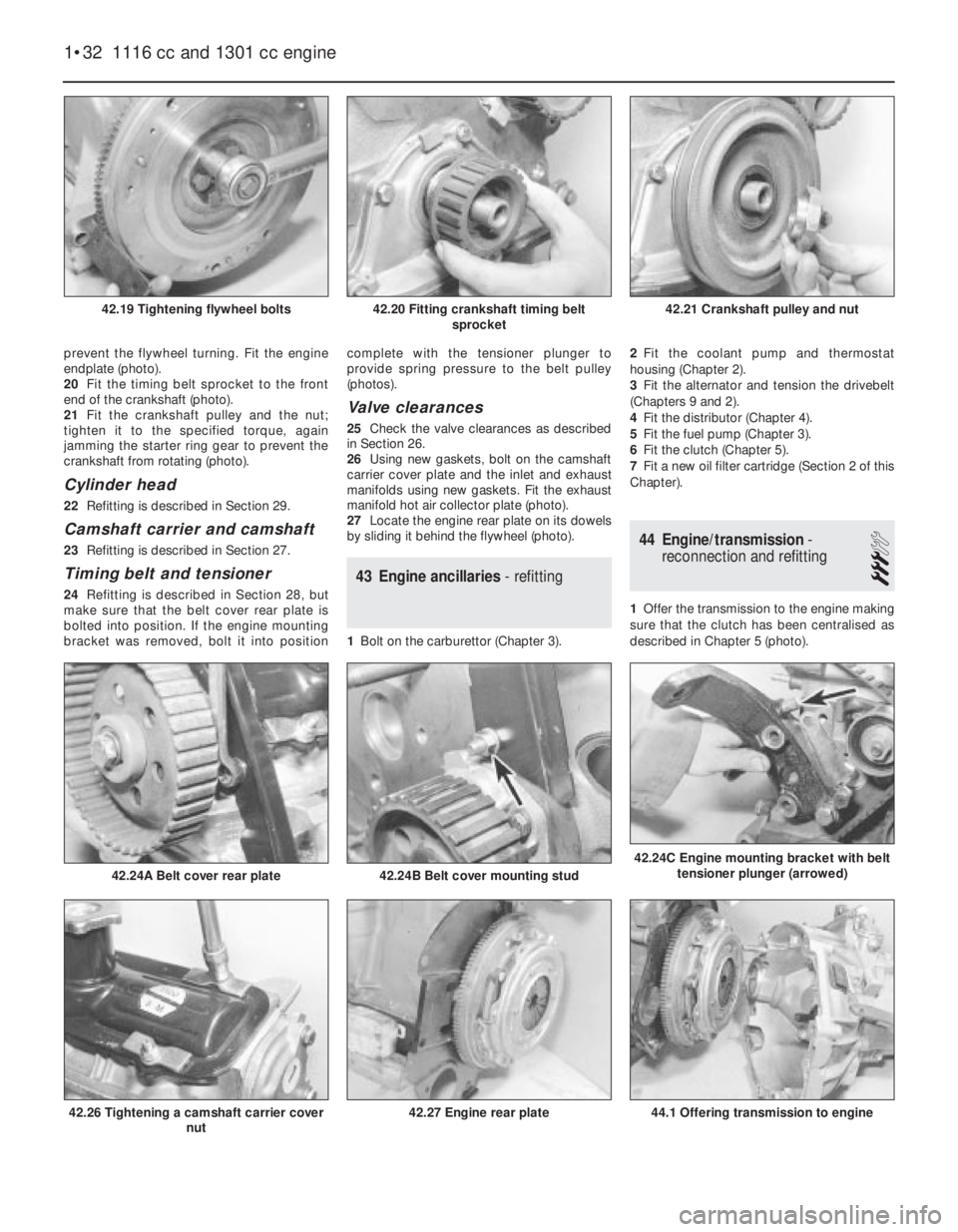
prevent the flywheel turning. Fit the engine
endplate (photo).
20Fit the timing belt sprocket to the front
end of the crankshaft (photo).
21Fit the crankshaft pulley and the nut;
tighten it to the specified torque, again
jamming the starter ring gear to prevent the
crankshaft from rotating (photo).
Cylinder head
22Refitting is described in Section 29.
Camshaft carrier and camshaft
23Refitting is described in Section 27.
Timing belt and tensioner
24Refitting is described in Section 28, but
make sure that the belt cover rear plate is
bolted into position. If the engine mounting
bracket was removed, bolt it into positioncomplete with the tensioner plunger to
provide spring pressure to the belt pulley
(photos).
Valve clearances
25Check the valve clearances as described
in Section 26.
26Using new gaskets, bolt on the camshaft
carrier cover plate and the inlet and exhaust
manifolds using new gaskets. Fit the exhaust
manifold hot air collector plate (photo).
27Locate the engine rear plate on its dowels
by sliding it behind the flywheel (photo).
43 Engine ancillaries- refitting
1Bolt on the carburettor (Chapter 3). 2Fit the coolant pump and thermostat
housing (Chapter 2).
3Fit the alternator and tension the drivebelt
(Chapters 9 and 2).
4Fit the distributor (Chapter 4).
5Fit the fuel pump (Chapter 3).
6Fit the clutch (Chapter 5).
7Fit a new oil filter cartridge (Section 2 of this
Chapter).
44 Engine/transmission-
reconnection and refitting
3
1Offer the transmission to the engine making
sure that the clutch has been centralised as
described in Chapter 5 (photo).
1•32 1116 cc and 1301 cc engine
44.1 Offering transmission to engine42.27 Engine rear plate42.26 Tightening a camshaft carrier cover
nut
42.24C Engine mounting bracket with belt
tensioner plunger (arrowed)
42.24B Belt cover mounting stud42.24A Belt cover rear plate
42.21 Crankshaft pulley and nut42.20 Fitting crankshaft timing belt
sprocket42.19 Tightening flywheel bolts
Page 50 of 303
Engine idles roughly
m mMixture too weak
m mAir leak in carburettor
m mAir leak at inlet manifold to cylinder head, or inlet manifold to
carburettor
m mCarburettor incorrectly adjusted
m mOther fuel system fault (see Chapter 3)
m mLow tension leads on coil loose
m mLow tension lead to distributor loose
m mDirty, incorrectly set, or pitted contact breaker points
m mTracking across inside of distributor cover
m mFaulty coil
m mIgnition leads loose
m mSpark plugs fouled or incorrectly gapped.
m mIgnition timing incorrect
m mOther ignition fault (see Chapter 4)
m mIncorrect valve clearances
m mWidely differing cylinder compressions
m mLow battery voltage (charging fault)
m mBattery leads loose on terminals
m mBattery earth strap loose on body attachment point
m mEngine earth lead loose
Pre-ignition (pinking) during acceleration
m
mIncorrect grade of fuel being used
m mIgnition timing over-advanced
m mOther ignition fault (see Chapter 4)
m mEngine overheated
m mExcessive carbon build-up
m mFuel system fault (see Chapter 3)
m mValve timing incorrect (after rebuild)
m mMixture too weak
Engine runs on after switching off
m
mIdle speed too high
m mIncorrect type of spark plug
m mOverheating
m mExcessive carbon build-up
m mOther emission control fault (see Chapter 3)
Oil being lost due to leaks
m
mLeaking oil filter gasket
m mLeaking rocker cover gasket
m mLeaking timing gear cover gasket
m mLeaking sump gasket
m mLoose sump plug
Low oil pressure (verify accuracy of sender before
dismantling engine!)
m mOil level low
m mEngine overheating
m mIncorrect grade of oil in use
m mOil filter clogged or bypass valve stuck
m mPressure relief valve stuck or defective
m mOil pick-up strainer clogged or loose
m mMain or big-end bearings worn
m mOil pump worn or mountings loose
Excessive oil consumption
m
mOverfilling
m mLeaking gaskets or drain plug washer
m mValve stem oil seals worn, damaged or missing after rebuild
m mValve stems and/or guides worn
m mPiston rings and/or bores worn
m mPiston oil return holes clogged
Oil contaminated with water
m
mExcessive cold running
m mLeaking head gasket
m mCracked block or head
Oil contaminated with fuel
m
mExcessive use of choke
m mWorn piston rings and/or bores
Unusual mechanical noises
m
mUnintentional mechanical contact (eg fan blade)
m mWorn drivebelt
m mWorn valvegear (tapping noises from top of engine) or incorrect
clearance
m mPeripheral component fault (generator, coolant pump)
m mWorn big-end bearings (regular heavy knocking, perhaps less under
load)
m mWorn main bearings (rumbling and knocking, perhaps worsening
under load)
m mSmall-end bushes or gudgeon pins worn (light metallic tapping)
m mPiston slap (most noticeable when engine cold)
m mWorn timing chain and gears (rattling from front of engine)
m mWorn crankshaft (knocking, rumbling and vibration)
1•36 All engines
Page 51 of 303
2
System type . . . . . . . . . . . . . . . . . . . . . . . . . . . . . . . . . . . . . . . . . . . “No loss” with radiator and integral expansion tank. Electric cooling
fan, belt-driven coolant pump, thermostat on cylinder head
General
Radiator fan cuts in . . . . . . . . . . . . . . . . . . . . . . . . . . . . . . . . . . . . . . . . . 90 to 94ºC (194 to 201ºF)
Radiator fan switches off . . . . . . . . . . . . . . . . . . . . . . . . . . . . . . . . . . . . 85 to 89ºC (185 to 192ºF)
Thermostat opens:
903 cc engine . . . . . . . . . . . . . . . . . . . . . . . . . . . . . . . . . . . . . . . . . . . 85 to 89ºC (185 to 192ºF)
1116 cc and 1301 cc engines . . . . . . . . . . . . . . . . . . . . . . . . . . . . . . . 83 to 87ºC (181 to 188.6ºF)
Fully open:
903 cc . . . . . . . . . . . . . . . . . . . . . . . . . . . . . . . . . . . . . . . . . . . . . . . . . 100ºC (212ºF)
1116 cc and 1301 cc . . . . . . . . . . . . . . . . . . . . . . . . . . . . . . . . . . . . . 95ºC (203ºF)
Expansion tank pressure cap rating . . . . . . . . . . . . . . . . . . . . . . . . . . . . 0.78 bar (11 lbf/in2)
Coolant
Capacity:
903 cc . . . . . . . . . . . . . . . . . . . . . . . . . . . . . . . . . . . . . . . . . . . . . . . . . 4.6 litre (8.1 pint)
1116 cc . . . . . . . . . . . . . . . . . . . . . . . . . . . . . . . . . . . . . . . . . . . . . . . . 6.0 litre (10.6 pint)
1301 cc . . . . . . . . . . . . . . . . . . . . . . . . . . . . . . . . . . . . . . . . . . . . . . . . 6.2 litre (10.9 pint)
Type . . . . . . . . . . . . . . . . . . . . . . . . . . . . . . . . . . . . . . . . . . . . . . . . . . . . Ethylene glycol based antifreeze
Torque wrench settingsNm lbf ft
Temperature sender switch . . . . . . . . . . . . . . . . . . . . . . . . . . . . . . . . . . 49 36
Coolant pump mounting bolts . . . . . . . . . . . . . . . . . . . . . . . . . . . . . . . . 34 25
Alternator adjuster and mountings nuts . . . . . . . . . . . . . . . . . . . . . . . . . 49 36
Chapter 2 Cooling and heating systems
For modifications, and information applicable to later models, see Supplement at end of manual
Coolant mixtures . . . . . . . . . . . . . . . . . . . . . . . . . . . . . . . . . . . . . . . . 3
Coolant pump - removal, overhaul and refitting . . . . . . . . . . . . . . . . 9
Cooling system - draining, flushing and refilling . . . . . . . . . . . . . . . . 2
Cooling system sensors . . . . . . . . . . . . . . . . . . . . . . . . . . . . . . . . . . 10
Description and maintenance . . . . . . . . . . . . . . . . . . . . . . . . . . . . . . 1
Drivebelt - tensioning and renewal . . . . . . . . . . . . . . . . . . . . . . . . . . 8
Fault finding - cooling and heating . . . . . . . . . . . . See end of ChapterHeater - dismantling, overhaul and reassembly . . . . . . . . . . . . . . . . 13
Heater unit - removal and refitting . . . . . . . . . . . . . . . . . . . . . . . . . . 12
Heating and ventilation system - description . . . . . . . . . . . . . . . . . . 11
Radiator - removal and refitting . . . . . . . . . . . . . . . . . . . . . . . . . . . . 7
Radiator fan thermostatic switch - removal, checking and refitting . 5
Radiator fan - removal and refitting . . . . . . . . . . . . . . . . . . . . . . . . . 6
Thermostat - removal, testing and refitting . . . . . . . . . . . . . . . . . . . . 4
2•1
Specifications Contents
1 Description and
maintenance
1
1The cooling system consists of a
front-mounted radiator with built-in expansion
tank, a coolant pump (belt-driven from the
crankshaft pulley) and a thermostatically-
controlled electric cooling fan.
2In order to assist rapid warm-up, athermostat is located in a housing at the
left-hand end of the cylinder head. The hose
connections to the thermostat housing vary
according to model.
3The heater is supplied with coolant from the
engine and incorporates a matrix and blower
with the necessary controls.
4The throttle valve plate block of the
carburettor is coolant-heated as a means of
improving fuel atomisation.
5Maintenance is minimal as in theory no
coolant should ever be lost from theexpansion tank. Regularly check that the
coolant level is between 50.0 and 70.0 mm
(1.97 and 2.8 in) above the MIN mark on the
tank with the engine cold. The need for
regular topping up will indicate a leak
somewhere in the system. If one cannot be
found suspect an internal leak in the engine
although this is usually confirmed by a rise in
the engine oil level and water on the dipstick
(photo). Any topping-up should be done using
an antifreeze mixture (see Section 3), not plain
water.
Easy,suitable for
novice with little
experienceFairly easy,suitable
for beginner with
some experienceFairly difficult,
suitable for competent
DIY mechanic
Difficult,suitable for
experienced DIY
mechanicVery difficult,
suitable for expert DIY
or professional
Degrees of difficulty
54321
Page 63 of 303
12The air cleaner on the 1301 cc engine is
mounted on the four flange studs of the
carburettors, their nuts being accessible after
the air cleaner lid has been removed and the
filter element extracted.
13Refitting of all types of air cleaner is a
reversal of removal.
3 Fuel pump-
removal and refitting
2
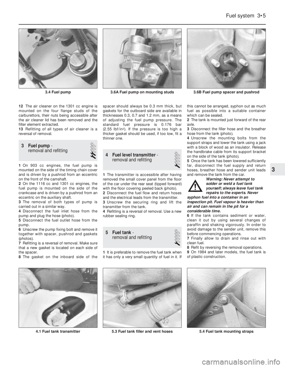
1On 903 cc engines, the fuel pump is
mounted on the side of the timing chain cover
and is driven by a pushrod from an eccentric
on the front of the camshaft.
2On the 1116 cc and 1301 cc engines, the
fuel pump is mounted on the side of the
crankcase and is driven by a pushrod from an
eccentric on the auxiliary shaft.
3The removal of both types of pump is
carried out in a similar way.
4Disconnect the fuel inlet hose from the
pump and plug the hose (photo).
5Disconnect the fuel outlet hose from the
pump.
6Unscrew the pump fixing bolt and remove it
together with spacer, pushrod and gaskets
(photos).
7Refitting is a reversal of removal. Make sure
that a new gasket is located on each side of
the spacer.
8The gasket on the inboard side of thespacer should always be 0.3 mm thick, but
gaskets for the outboard side are available in
thicknesses 0.3, 0.7 and 1.2 mm, as a means
of adjusting the fuel pump pressure. The
standard fuel pressure is 0.176 bar
(2.55 lbf/in
2). If the pressure is too high a
thicker gasket should be used, if too low, fit a
thinner one.
4 Fuel level transmitter-
removal and refitting
1
1The transmitter is accessible after having
removed the small cover panel from the floor
of the car under the rear seat (tipped forward)
with the floor covering peeled back (photo).
2Disconnect the fuel flow and return hoses
and the electrical leads from the transmitter.
3Unscrew the securing ring and lift the
transmitter from the tank.
4Refitting is a reversal of removal. Use a new
rubber sealing ring.
5 Fuel tank-
removal and refitting
1
1It is preferable to remove the fuel tank when
it has only a very small quantity of fuel in it. Ifthis cannot be arranged, syphon out as much
fuel as possible into a suitable container
which can be sealed.
2The tank is mounted just forward of the rear
axle.
3Disconnect the filler hose and the breather
hose from the tank (photo).
4Unscrew the mounting bolts from the
support straps and lower the tank using a jack
with a block of wood as an insulator. Release
the handbrake cable from its support bracket
on the side of the tank (photo).
5Once the tank has been lowered sufficiently
far, disconnect the fuel supply and return
hoses, breather hose and sender unit leads
and remove the tank from the car.
Warning: Never attempt to
solder or weld a fuel tank
yourself; always leave fuel tank
repairs to the experts. Never
syphon fuel into a container in an
inspection pit. Fuel vapour is heavier than
air and can remain in the pit for a
considerable time.
6If the tank contains sediment or water,
clean it out by using several changes of
paraffin and shaking vigorously. In order to
avoid damage to the sender unit, remove this
before commencing operations.
7Finally allow to drain and rinse out with
clean fuel.
8Refit by reversing the removal operations.
9On 1984 and later models, the fuel tank is
of plastic construction.
Fuel system 3•5
3.6B Fuel pump spacer and pushrod3.6A Fuel pump on mounting studs3.4 Fuel pump
5.4 Fuel tank mounting straps5.3 Fuel tank filler and vent hoses4.1 Fuel tank transmitter
3
Page 65 of 303
7 Carburettor idle speed and
mixture- adjustment
4
1All carburettors have their mixture
adjustment set in production. The screw is
fitted with a tamperproof cap.
2Under normal circumstances, only the idle
speed screw need be adjusted to set the
engine idle speed to the specified level.
3Before attempting to adjust the idle speed
or mixture, it is important to have the ignition
and valve clearances correctly set and the
engine at normal operating temperature with
the air cleaner fitted.
4Where the mixture must be adjusted, prise
out the tamperproof plug and turn the mixture
screw in to weaken or out to enrich the
mixture until the engine runs smoothly without
any tendency to “hunt”.
5Ideally an exhaust gas analyser should be
used to make sure that the CO level is within
the specified range.
6Once the mixture has been correctly set,
re-adjust the idle speed screw.
8 Carburettor-
removal and refitting
2
1Remove the air cleaner.
2Disconnect the flow and return fuel hoses
from the carburettor and plug them.3Disconnect the coolant hoses from the
carburettor throttle valve plate block.
Provided the cooling system is cold and not
under pressure there should be almost no loss
of coolant. Tie the hoses up as high as
possible with a piece of wire.
4Disconnect the vacuum and vent hoses
from the carburettor.
5Disconnect the throttle and choke controls
from the carburettor.
6Unscrew the mounting flange nuts and lift
the carburettor from the intake manifold
(photo).
7Refitting is a reversal of removal. Use a new
flange gasket and make sure that the fuel
return hose is routed above the air cleaner
intake.
9 Carburettor
(Weber 32 ICEV 50/250/1)-
servicing and adjustment
4
1The carburettor top cover with float may be
removed without the need to withdraw the
carburettor from the manifold. The other
adjustments described will require removal of
the carburettor.
2Unscrew the filter plug from the top cover,
clean the filter screen and refit it.
3Extract the top cover fixing screws, lift the
cover and tilt it to unhook it from the
diaphragm capsule link rod.
4Access to the fuel inlet needle valve isobtained by carefully tapping out the float arm
pivot pin. Take care, the pivot pin pillars are
very brittle.
5Check that the needle valve body is tight
otherwise fuel can bypass the needle valve
and cause flooding.
Float adjustment
6Reassemble and check the float setting. Do
this by holding the top cover vertically so that
the float hangs down under its own weight.
Measure dimension (A) (Fig. 3.10) which
should be between 1 0.50 and 11.10 mm
(0.41 to 0.44 in) with the gasket in position. If
necessary, bend the float arm tab to adjust.
7Now check the float travel which should be
45.0 mm (1.77 in). If adjustment is required,
bend the end of the float arm.
Accelerator pump stroke
8Using a twist drill as a gauge, open the
throttle valve plate through 3.5 mm (0.138 in).
9Turn the nut on the accelerator pump rod
until it just makes contact with the pump
control lever.
Fast idle adjustment
10With the choke valve plate fully closed by
means of the control lever, the throttle valve
Fuel system 3•7
Fig. 3.9 Fuel return hose correctly located
(Sec 8)
8.6 Carburettor mounting flange nut8.2 Fuel hose at carburettor
Fig. 3.10 Float setting diagram (Weber 32 ICEV 50/250) (Sec 9)
A = 10.5 to 11.0 mm (0.41 to 0.44 in) B = 45.0 mm (1.77 in)Fig. 3.11 Accelerator pump setting diagram
(Weber 32 ICEV 50/250) (Sec 9)
X = 3.5 mm (0.138 in)
3