fuel tank removal FIAT UNO 1983 Service Repair Manual
[x] Cancel search | Manufacturer: FIAT, Model Year: 1983, Model line: UNO, Model: FIAT UNO 1983Pages: 303, PDF Size: 10.36 MB
Page 51 of 303
2
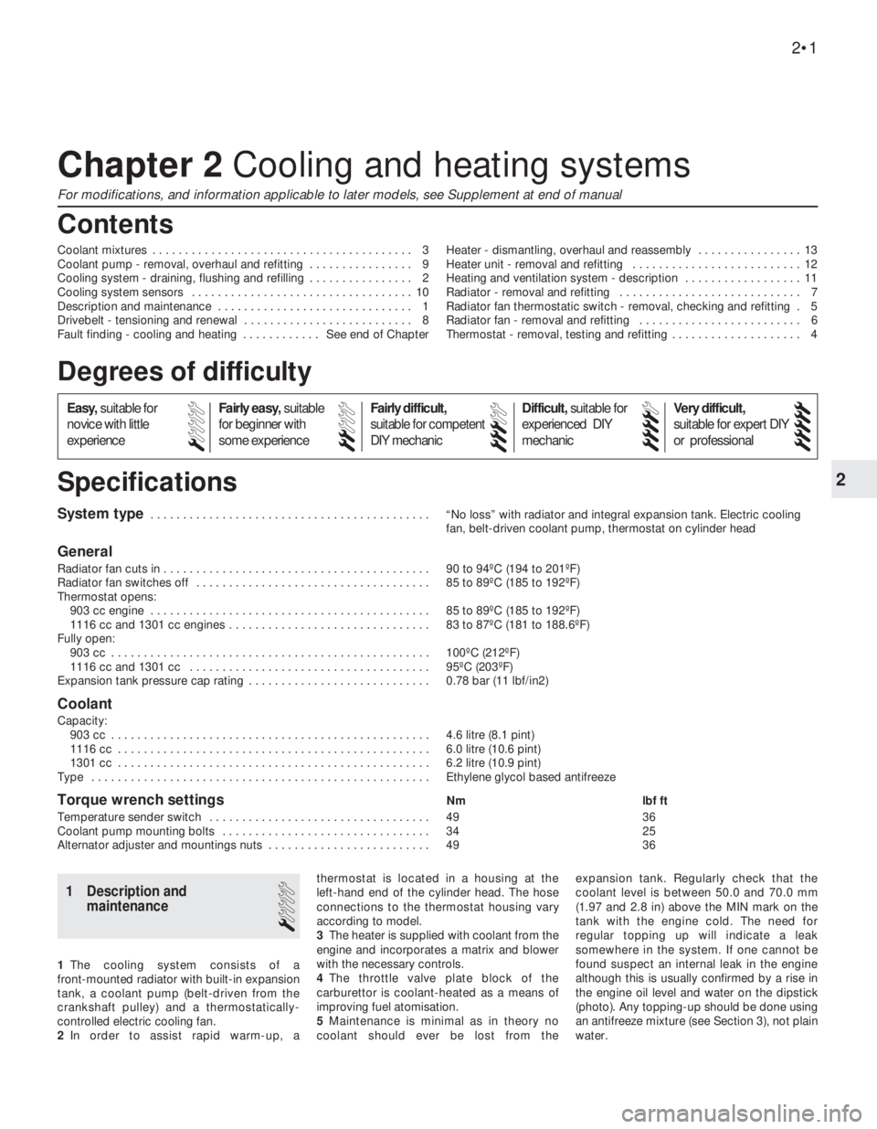
System type . . . . . . . . . . . . . . . . . . . . . . . . . . . . . . . . . . . . . . . . . . . “No loss” with radiator and integral expansion tank. Electric cooling
fan, belt-driven coolant pump, thermostat on cylinder head
General
Radiator fan cuts in . . . . . . . . . . . . . . . . . . . . . . . . . . . . . . . . . . . . . . . . . 90 to 94ºC (194 to 201ºF)
Radiator fan switches off . . . . . . . . . . . . . . . . . . . . . . . . . . . . . . . . . . . . 85 to 89ºC (185 to 192ºF)
Thermostat opens:
903 cc engine . . . . . . . . . . . . . . . . . . . . . . . . . . . . . . . . . . . . . . . . . . . 85 to 89ºC (185 to 192ºF)
1116 cc and 1301 cc engines . . . . . . . . . . . . . . . . . . . . . . . . . . . . . . . 83 to 87ºC (181 to 188.6ºF)
Fully open:
903 cc . . . . . . . . . . . . . . . . . . . . . . . . . . . . . . . . . . . . . . . . . . . . . . . . . 100ºC (212ºF)
1116 cc and 1301 cc . . . . . . . . . . . . . . . . . . . . . . . . . . . . . . . . . . . . . 95ºC (203ºF)
Expansion tank pressure cap rating . . . . . . . . . . . . . . . . . . . . . . . . . . . . 0.78 bar (11 lbf/in2)
Coolant
Capacity:
903 cc . . . . . . . . . . . . . . . . . . . . . . . . . . . . . . . . . . . . . . . . . . . . . . . . . 4.6 litre (8.1 pint)
1116 cc . . . . . . . . . . . . . . . . . . . . . . . . . . . . . . . . . . . . . . . . . . . . . . . . 6.0 litre (10.6 pint)
1301 cc . . . . . . . . . . . . . . . . . . . . . . . . . . . . . . . . . . . . . . . . . . . . . . . . 6.2 litre (10.9 pint)
Type . . . . . . . . . . . . . . . . . . . . . . . . . . . . . . . . . . . . . . . . . . . . . . . . . . . . Ethylene glycol based antifreeze
Torque wrench settingsNm lbf ft
Temperature sender switch . . . . . . . . . . . . . . . . . . . . . . . . . . . . . . . . . . 49 36
Coolant pump mounting bolts . . . . . . . . . . . . . . . . . . . . . . . . . . . . . . . . 34 25
Alternator adjuster and mountings nuts . . . . . . . . . . . . . . . . . . . . . . . . . 49 36
Chapter 2 Cooling and heating systems
For modifications, and information applicable to later models, see Supplement at end of manual
Coolant mixtures . . . . . . . . . . . . . . . . . . . . . . . . . . . . . . . . . . . . . . . . 3
Coolant pump - removal, overhaul and refitting . . . . . . . . . . . . . . . . 9
Cooling system - draining, flushing and refilling . . . . . . . . . . . . . . . . 2
Cooling system sensors . . . . . . . . . . . . . . . . . . . . . . . . . . . . . . . . . . 10
Description and maintenance . . . . . . . . . . . . . . . . . . . . . . . . . . . . . . 1
Drivebelt - tensioning and renewal . . . . . . . . . . . . . . . . . . . . . . . . . . 8
Fault finding - cooling and heating . . . . . . . . . . . . See end of ChapterHeater - dismantling, overhaul and reassembly . . . . . . . . . . . . . . . . 13
Heater unit - removal and refitting . . . . . . . . . . . . . . . . . . . . . . . . . . 12
Heating and ventilation system - description . . . . . . . . . . . . . . . . . . 11
Radiator - removal and refitting . . . . . . . . . . . . . . . . . . . . . . . . . . . . 7
Radiator fan thermostatic switch - removal, checking and refitting . 5
Radiator fan - removal and refitting . . . . . . . . . . . . . . . . . . . . . . . . . 6
Thermostat - removal, testing and refitting . . . . . . . . . . . . . . . . . . . . 4
2•1
Specifications Contents
1 Description and
maintenance
1
1The cooling system consists of a
front-mounted radiator with built-in expansion
tank, a coolant pump (belt-driven from the
crankshaft pulley) and a thermostatically-
controlled electric cooling fan.
2In order to assist rapid warm-up, athermostat is located in a housing at the
left-hand end of the cylinder head. The hose
connections to the thermostat housing vary
according to model.
3The heater is supplied with coolant from the
engine and incorporates a matrix and blower
with the necessary controls.
4The throttle valve plate block of the
carburettor is coolant-heated as a means of
improving fuel atomisation.
5Maintenance is minimal as in theory no
coolant should ever be lost from theexpansion tank. Regularly check that the
coolant level is between 50.0 and 70.0 mm
(1.97 and 2.8 in) above the MIN mark on the
tank with the engine cold. The need for
regular topping up will indicate a leak
somewhere in the system. If one cannot be
found suspect an internal leak in the engine
although this is usually confirmed by a rise in
the engine oil level and water on the dipstick
(photo). Any topping-up should be done using
an antifreeze mixture (see Section 3), not plain
water.
Easy,suitable for
novice with little
experienceFairly easy,suitable
for beginner with
some experienceFairly difficult,
suitable for competent
DIY mechanic
Difficult,suitable for
experienced DIY
mechanicVery difficult,
suitable for expert DIY
or professional
Degrees of difficulty
54321
Page 59 of 303
3
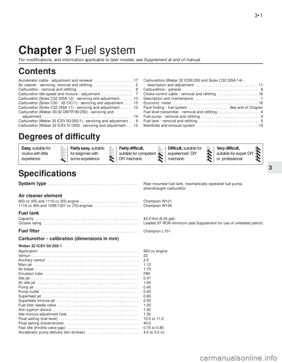
System type . . . . . . . . . . . . . . . . . . . . . . . . . . . . . . . . . . . . . . . . . . . Rear mounted fuel tank, mechanically-operated fuel pump,
downdraught carburettor
Air cleaner element
903 cc (45) and 1116 cc (55) engine . . . . . . . . . . . . . . . . . . . . . . . . . . . . Champion W121
1116 cc (60) and 1299/1301 cc (70) engines . . . . . . . . . . . . . . . . . . . . . Champion W136
Fuel tank
Capacity . . . . . . . . . . . . . . . . . . . . . . . . . . . . . . . . . . . . . . . . . . . . . . . . . 42.0 litre (9.25 gal)
Octane rating . . . . . . . . . . . . . . . . . . . . . . . . . . . . . . . . . . . . . . . . . . . . . Leaded 97 RON minimum (see Supplement for use of unleaded petrol)
Fuel filter . . . . . . . . . . . . . . . . . . . . . . . . . . . . . . . . . . . . . . . . . . . . . . Champion L101
Carburettor - calibration (dimensions in mm)
Weber 32 ICEV 50/250/1
Application . . . . . . . . . . . . . . . . . . . . . . . . . . . . . . . . . . . . . . . . . . . . . . . 903 cc engine
Venturi . . . . . . . . . . . . . . . . . . . . . . . . . . . . . . . . . . . . . . . . . . . . . . . . . . . 22
Auxiliary venturi . . . . . . . . . . . . . . . . . . . . . . . . . . . . . . . . . . . . . . . . . . . 3.5
Main jet . . . . . . . . . . . . . . . . . . . . . . . . . . . . . . . . . . . . . . . . . . . . . . . . . . 1.12
Air bleed . . . . . . . . . . . . . . . . . . . . . . . . . . . . . . . . . . . . . . . . . . . . . . . . . 1.70
Emulsion tube . . . . . . . . . . . . . . . . . . . . . . . . . . . . . . . . . . . . . . . . . . . . . F89
Idle jet . . . . . . . . . . . . . . . . . . . . . . . . . . . . . . . . . . . . . . . . . . . . . . . . . . . 0.47
Air idle jet . . . . . . . . . . . . . . . . . . . . . . . . . . . . . . . . . . . . . . . . . . . . . . . . 1.60
Pump jet . . . . . . . . . . . . . . . . . . . . . . . . . . . . . . . . . . . . . . . . . . . . . . . . . 0.40
Pump outlet . . . . . . . . . . . . . . . . . . . . . . . . . . . . . . . . . . . . . . . . . . . . . . 0.40
Superfeed jet . . . . . . . . . . . . . . . . . . . . . . . . . . . . . . . . . . . . . . . . . . . . . 0.80
Superfeed mixture jet . . . . . . . . . . . . . . . . . . . . . . . . . . . . . . . . . . . . . . . 2.50
Fuel inlet needle valve . . . . . . . . . . . . . . . . . . . . . . . . . . . . . . . . . . . . . . 1.50
Anti-syphon device . . . . . . . . . . . . . . . . . . . . . . . . . . . . . . . . . . . . . . . . . 1.00
Idle mixture adjustment hole . . . . . . . . . . . . . . . . . . . . . . . . . . . . . . . . . 1.50
Float setting (fuel level) . . . . . . . . . . . . . . . . . . . . . . . . . . . . . . . . . . . . . . 10.5 to 11.0
Float setting (travel/stroke) . . . . . . . . . . . . . . . . . . . . . . . . . . . . . . . . . . . 45.0
Fast idle (throttle valve gap) . . . . . . . . . . . . . . . . . . . . . . . . . . . . . . . . . . 0.75 to 0.80
Accelerator pump delivery (ten strokes) . . . . . . . . . . . . . . . . . . . . . . . . . 4.0 to 5.5 cc
Chapter 3 Fuel system
For modifications, and information applicable to later models, see Supplement at end of manual
Accelerator cable - adjustment and renewal . . . . . . . . . . . . . . . . . . 17
Air cleaner - servicing, removal and refitting . . . . . . . . . . . . . . . . . . . 2
Carburettor - removal and refitting . . . . . . . . . . . . . . . . . . . . . . . . . . 8
Carburettor idle speed and mixture - adjustment . . . . . . . . . . . . . . . 7
Carburettor (Solex C32 DISA 12) - servicing and adjustment . . . . . . 13
Carburettor (Solex C30 - 32 CIC/1) - servicing and adjustment . . . . 15
Carburettor (Solex C32 DISA 11) - servicing and adjustment . . . . . . 10
Carburettor (Weber 30/32 DMTR 90/250) - servicing and
adjustment . . . . . . . . . . . . . . . . . . . . . . . . . . . . . . . . . . . . . . . . . . . 14
Carburettor (Weber 32 ICEV 50/250/1) - servicing and adjustment . . 9
Carburettor (Weber 32 ICEV 51/250) - servicing and adjustment . . . 12Carburettors (Weber 32 ICEE/250 and Solex C32 DISA 14) -
description and adjustment . . . . . . . . . . . . . . . . . . . . . . . . . . . . . . 11
Carburettors - general . . . . . . . . . . . . . . . . . . . . . . . . . . . . . . . . . . . . 6
Choke control cable - removal and refitting . . . . . . . . . . . . . . . . . . . 18
Description and maintenance . . . . . . . . . . . . . . . . . . . . . . . . . . . . . . 1
Economy meter . . . . . . . . . . . . . . . . . . . . . . . . . . . . . . . . . . . . . . . . 16
Fault finding - fuel system . . . . . . . . . . . . . . . . . . . See end of Chapter
Fuel level transmitter - removal and refitting . . . . . . . . . . . . . . . . . . . 4
Fuel pump - removal and refitting . . . . . . . . . . . . . . . . . . . . . . . . . . . 3
Fuel tank - removal and refitting . . . . . . . . . . . . . . . . . . . . . . . . . . . . 5
Manifolds and exhaust system . . . . . . . . . . . . . . . . . . . . . . . . . . . . . 19
3•1
Specifications Contents
Easy,suitable for
novice with little
experienceFairly easy,suitable
for beginner with
some experienceFairly difficult,
suitable for competent
DIY mechanic
Difficult,suitable for
experienced DIY
mechanicVery difficult,
suitable for expert DIY
or professional
Degrees of difficulty
54321
Page 62 of 303
Engine idle speed
At normal operating temperature . . . . . . . . . . . . . . . . . . . . . . . . . . . . . . 800 to 850 rev/min
CO percentage at idle . . . . . . . . . . . . . . . . . . . . . . . . . . . . . . . . . 3.5 maximum
Torque wrench settingsNm lbf ft
Exhaust manifold nuts (903 cc) . . . . . . . . . . . . . . . . . . . . . . . . . . . . . . . 20 15
Exhaust and intake manifold nuts (1116 cc, 1301 cc) . . . . . . . . . . . . . . 28 20
Fuel pump nuts . . . . . . . . . . . . . . . . . . . . . . . . . . . . . . . . . . . . . . . . . . . . 28 20
Carburettor mounting nuts . . . . . . . . . . . . . . . . . . . . . . . . . . . . . . . . . . . 25 18
3•4 Fuel system
2.11B Air cleaner mounting bracket and
pipe clip2.11A Air cleaner mounting studs (1116 cc)2.9 Crankcase vent hose at air cleaner
1 Description and
maintenance
1
1The fuel system consists of a rear-mounted
fuel tank, a mechanically-operated fuel pump
and a carburettor and air cleaner.
2On all engines except the 1301 cc a single
venturi downdraught carburettor is fitted. On
the 1301 cc version, a dual barrel carburettor
is fitted.
3Maintenance consists of periodically
checking the condition and security of the fuel
hoses to the pump and carburettor. The fuel
pump cannot be cleaned or repaired and in
the event of a fault developing, the pump
must be renewed.
4On ES versions, an electronic fuel cut-out
device is fitted which reduces fuel
consumption on overrun, see Chapter 9,
Section 33.
2 Air cleaner- servicing,
removal and refitting
1
1The air cleaner air intake draws air either
from the front of the car or from the outside of
the exhaust manifold according to ambient
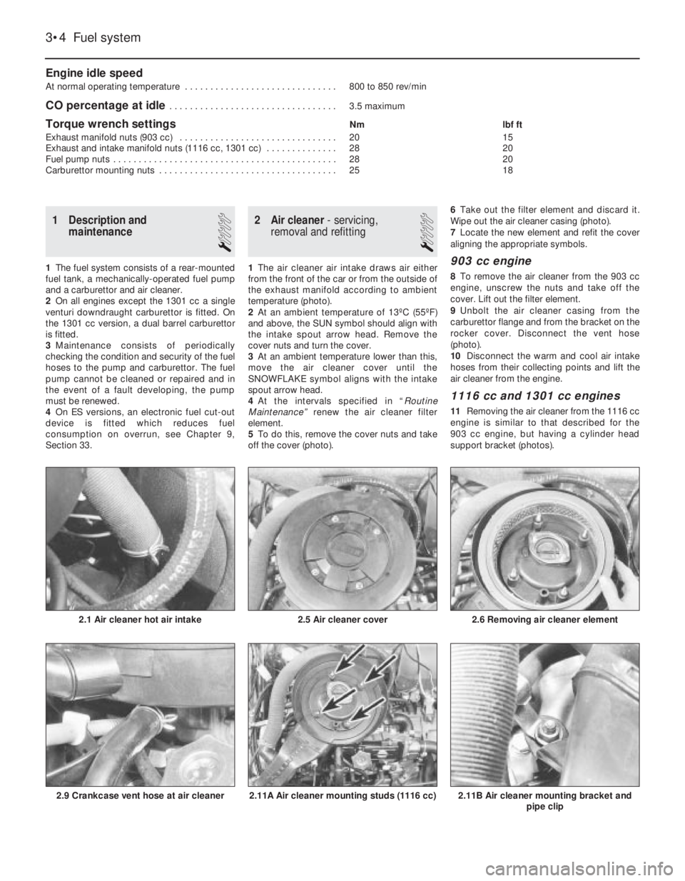
temperature (photo).
2At an ambient temperature of 13ºC (55ºF)
and above, the SUN symbol should align with
the intake spout arrow head. Remove the
cover nuts and turn the cover.
3At an ambient temperature lower than this,
move the air cleaner cover until the
SNOWFLAKE symbol aligns with the intake
spout arrow head.
4At the intervals specified in “Routine
Maintenance” renew the air cleaner filter
element.
5To do this, remove the cover nuts and take
off the cover (photo).6Take out the filter element and discard it.
Wipe out the air cleaner casing (photo).
7Locate the new element and refit the cover
aligning the appropriate symbols.903 cc engine
8To remove the air cleaner from the 903 cc
engine, unscrew the nuts and take off the
cover. Lift out the filter element.
9Unbolt the air cleaner casing from the
carburettor flange and from the bracket on the
rocker cover. Disconnect the vent hose
(photo).
10Disconnect the warm and cool air intake
hoses from their collecting points and lift the
air cleaner from the engine.
1116 cc and 1301 cc engines
11Removing the air cleaner from the 1116 cc
engine is similar to that described for the
903 cc engine, but having a cylinder head
support bracket (photos).
2.6 Removing air cleaner element
2.5 Air cleaner cover2.1 Air cleaner hot air intake
Page 63 of 303
12The air cleaner on the 1301 cc engine is
mounted on the four flange studs of the
carburettors, their nuts being accessible after
the air cleaner lid has been removed and the
filter element extracted.
13Refitting of all types of air cleaner is a
reversal of removal.
3 Fuel pump-
removal and refitting
2
1On 903 cc engines, the fuel pump is
mounted on the side of the timing chain cover
and is driven by a pushrod from an eccentric
on the front of the camshaft.
2On the 1116 cc and 1301 cc engines, the
fuel pump is mounted on the side of the
crankcase and is driven by a pushrod from an
eccentric on the auxiliary shaft.
3The removal of both types of pump is
carried out in a similar way.
4Disconnect the fuel inlet hose from the
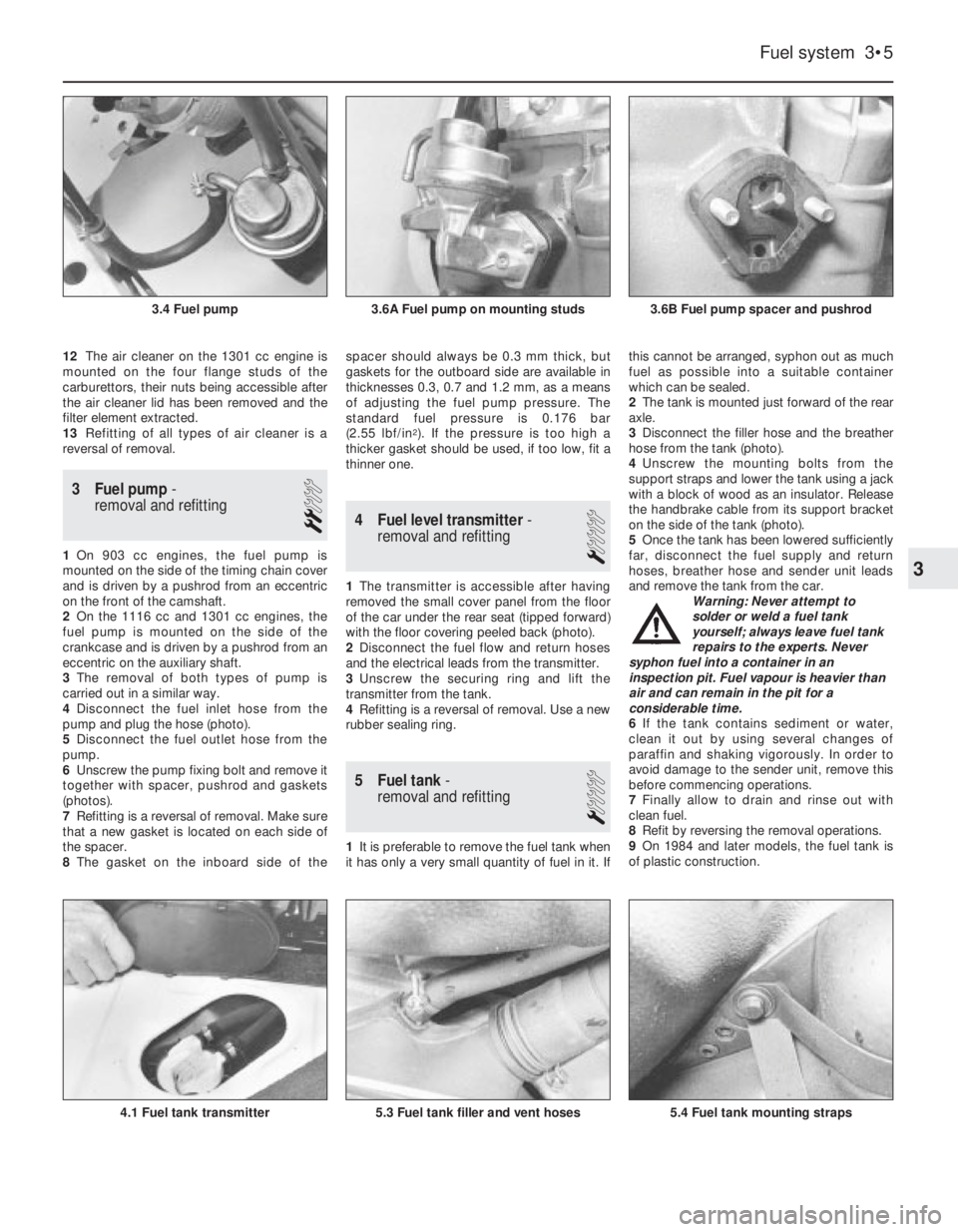
pump and plug the hose (photo).
5Disconnect the fuel outlet hose from the
pump.
6Unscrew the pump fixing bolt and remove it
together with spacer, pushrod and gaskets
(photos).
7Refitting is a reversal of removal. Make sure
that a new gasket is located on each side of
the spacer.
8The gasket on the inboard side of thespacer should always be 0.3 mm thick, but
gaskets for the outboard side are available in
thicknesses 0.3, 0.7 and 1.2 mm, as a means
of adjusting the fuel pump pressure. The
standard fuel pressure is 0.176 bar
(2.55 lbf/in
2). If the pressure is too high a
thicker gasket should be used, if too low, fit a
thinner one.
4 Fuel level transmitter-
removal and refitting
1
1The transmitter is accessible after having
removed the small cover panel from the floor
of the car under the rear seat (tipped forward)
with the floor covering peeled back (photo).
2Disconnect the fuel flow and return hoses
and the electrical leads from the transmitter.
3Unscrew the securing ring and lift the
transmitter from the tank.
4Refitting is a reversal of removal. Use a new
rubber sealing ring.
5 Fuel tank-
removal and refitting
1
1It is preferable to remove the fuel tank when
it has only a very small quantity of fuel in it. Ifthis cannot be arranged, syphon out as much
fuel as possible into a suitable container
which can be sealed.
2The tank is mounted just forward of the rear
axle.
3Disconnect the filler hose and the breather
hose from the tank (photo).
4Unscrew the mounting bolts from the
support straps and lower the tank using a jack
with a block of wood as an insulator. Release
the handbrake cable from its support bracket
on the side of the tank (photo).
5Once the tank has been lowered sufficiently
far, disconnect the fuel supply and return
hoses, breather hose and sender unit leads
and remove the tank from the car.
Warning: Never attempt to
solder or weld a fuel tank
yourself; always leave fuel tank
repairs to the experts. Never
syphon fuel into a container in an
inspection pit. Fuel vapour is heavier than
air and can remain in the pit for a
considerable time.
6If the tank contains sediment or water,
clean it out by using several changes of
paraffin and shaking vigorously. In order to
avoid damage to the sender unit, remove this
before commencing operations.
7Finally allow to drain and rinse out with
clean fuel.
8Refit by reversing the removal operations.
9On 1984 and later models, the fuel tank is
of plastic construction.
Fuel system 3•5
3.6B Fuel pump spacer and pushrod3.6A Fuel pump on mounting studs3.4 Fuel pump
5.4 Fuel tank mounting straps5.3 Fuel tank filler and vent hoses4.1 Fuel tank transmitter
3
Page 89 of 303
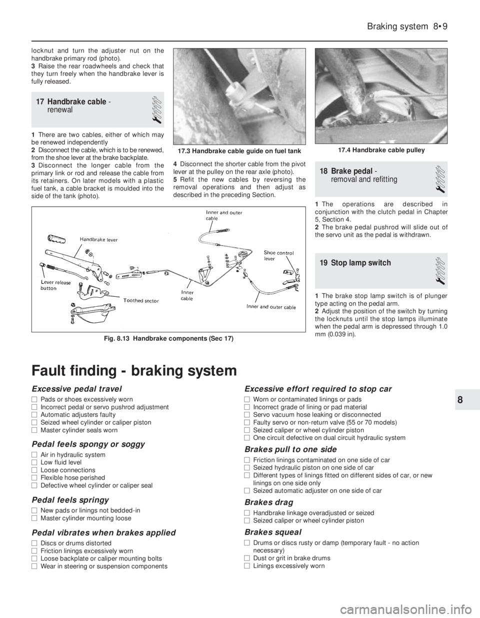
locknut and turn the adjuster nut on the
handbrake primary rod (photo).
3Raise the rear roadwheels and check that
they turn freely when the handbrake lever is
fully released.
17 Handbrake cable-
renewal
1
1There are two cables, either of which may
be renewed independently
2Disconnect the cable, which is to be renewed,
from the shoe lever at the brake backplate.
3Disconnect the longer cable from the
primary link or rod and release the cable from
its retainers. On later models with a plastic
fuel tank, a cable bracket is moulded into the
side of the tank (photo).4Disconnect the shorter cable from the pivot
lever at the pulley on the rear axle (photo).
5Refit the new cables by reversing the
removal operations and then adjust as
described in the preceding Section.
18 Brake pedal-
removal and refitting
1
1The operations are described in
conjunction with the clutch pedal in Chapter
5, Section 4.
2The brake pedal pushrod will slide out of
the servo unit as the pedal is withdrawn.
19 Stop lamp switch
1
1The brake stop lamp switch is of plunger
type acting on the pedal arm.
2Adjust the position of the switch by turning
the locknuts until the stop lamps illuminate
when the pedal arm is depressed through 1.0
mm (0.039 in).
Braking system 8•9
Fig. 8.13 Handbrake components (Sec 17)
17.4 Handbrake cable pulley17.3 Handbrake cable guide on fuel tank
8
Fault finding - braking system
Excessive pedal travel
m mPads or shoes excessively worn
m mIncorrect pedal or servo pushrod adjustment
m mAutomatic adjusters faulty
m mSeized wheel cylinder or caliper piston
m mMaster cylinder seals worn
Pedal feels spongy or soggy
m
mAir in hydraulic system
m mLow fluid level
m mLoose connections
m mFlexible hose perished
m mDefective wheel cylinder or caliper seal
Pedal feels springy
m
mNew pads or linings not bedded-in
m mMaster cylinder mounting loose
Pedal vibrates when brakes applied
m
mDiscs or drums distorted
m mFriction linings excessively worn
m mLoose backplate or caliper mounting bolts
m mWear in steering or suspension components
Excessive effort required to stop car
m
mWorn or contaminated linings or pads
m mIncorrect grade of lining or pad material
m mServo vacuum hose leaking or disconnected
m mFaulty servo or non-return valve (55 or 70 models)
m mSeized caliper or wheel cylinder piston
m mOne circuit defective on dual circuit hydraulic system
Brakes pull to one side
m
mFriction linings contaminated on one side of car
m mSeized hydraulic piston on one side of car
m mDifferent types of linings fitted on different sides of car, or new
linings on one side only
m mSeized automatic adjuster on one side of car
Brakes drag
m
mHandbrake linkage overadjusted or seized
m mSeized caliper or wheel cylinder piston
Brakes squeal
m
mDrums or discs rusty or damp (temporary fault - no action
necessary)
m mDust or grit in brake drums
m mLinings excessively worn
Page 127 of 303
Cooling system................................................................................. 8
Part A: 999 cc engine
Description
Maintenance
Thermostat - removal and refitting
Coolant pump - removal and refitting
Part B: 1301 cc Turbo ie engine
Description
Part C: 1372 cc ie and 1372 cc Turbo ie engines
Description
Maintenance
Cooling system - draining, flushing and refilling
Radiator (and cooling fan) - removal and refitting
Thermostat - removal and refitting
Coolant pump - removal and refitting
Coolant pump/alternator drivebelt - checking, renewal and
tensioning
Part D: Heater unit later models
Heater unit - removal and refitting
Heater unit - dismantling and reassembly
Fuel and exhaust systems............................................................... 9
Part A: General
Unleaded fuel
Air cleaner modified types
Fuel pump (999 cc engine) - description, removal and
refitting
Fuel tank (999 cc engine)
Part B: Carburettor models
Carburettor (Weber 32 TLF) - description
Carburettor (Weber 32 TLF) - idle speed and mixture
Carburettor (Weber 32 TLF) - removal and refitting
Carburettor (Weber 32 TLF) - overhaul
Carburettor (Weber 30/32 DMTE) - general
Carburettor (Weber 30/32 DMTE) - overhaul
Carburettor (Weber 32 ICEV 61/250 and DMTE 30/32,
DMTE 30/150) - general
Carburettor (Solex C 30/32-CIC 8) - description
Part C: Bosch LE-2 Jetronic fuel injection system
Description
Maintenance
Fuel filter - renewal
Air cleaner element - renewal
Idle speed and mixture - adjustment
Fuel injection system - electrical tests
Fuel injection system - mechanical tests
Fuel injection system components - removal and
refitting
Throttle control linkage - general
Fuel tank - general
Part D: Bosch Mono-Jetronic fuel injection system
Description
Maintenance
Fuel filter - renewal
Air cleaner element - renewal
Idle speed and mixture adjustment
Accelerator control system - check and adjustment
Fuel system - depressurisation
Fuel pump and supply - system checks
Fuel pump - removal and refitting
Injector unit - removal and refitting
Intake air temperature sensor - removal and refitting
Fuel injector - removal and refitting
Electronic control unit (ECU) - removal and refitting
Inlet manifold - removal and refitting
Exhaust manifold - removal and refitting
Catalytic converter - general information
Fuel evaporation control system - generalPart E: Bosch L3.1/2 Jetronic fuel injection systems
Description
Fuel system - depressurisation
Maintenance
Fuel filter - renewal
Air cleaner element - renewal
Checks and adjustments
Injection system components - removal and refitting
Part G: Turbocharger system
Description
Precautions
Turbocharger (1301 cc ie engine) - removal and refitting
Turbocharger (1372 cc ie engine) - removal and refitting
Intercooler - removal and refitting
Injector cooling fan - removal and refitting
Fault finding - fuel injection system
Fault finding - turbocharger system
Ignition system................................................................................. 10
General
Ignition timing (all later models)
Breakerless ignition system - description
Distributor (breakerless type) - removal and refitting
Distributor (breakerless type) - overhaul
Breakerless ignition system components - testing
Microplex ignition system - description
Distributor (Microplex) - removal and refitting
Microplex ignition system components - testing
Digiplex 2 ignition system - description
Distributor (Digiplex 2) - removal and refitting
Spark plugs and HT leads - general
Fault finding - Microplex ignition system
Clutch................................................................................................ 11
Clutch pedal adjustment (cable clutch)
Hydraulic clutch - description
Maintenance (hydraulic clutch)
Clutch master cylinder - removal, overhaul and
refitting
Clutch operating cylinder - removal, overhaul and
refitting
Clutch hydraulic system - bleeding
Transmission.................................................................................... 12
Part A: 1301 cc Turbo ie engine
Description
Gearchange linkage - removal and refitting
Gearchange linkage (Antiskid models) - general
Final drive output shafts - description and oil seal
renewal
Part B: 1372 cc ie and 1372 cc Turbo ie engines
Description
Maintenance
Oil level - checking
Oil - renewal
Gearlever and linkages - general
Transmission - removal and refitting
Part C: 999 and 1108 cc with C514 type transmission
Description
Maintenance
Driveshafts........................................................................................ 13
Inboard joint boots (non-Turbo models, September 1987 on) -
modification
Intermediate driveshaft (Turbo ie models)
Inboard CV joints (Turbo ie models - overhaul
Right-hand driveshaft damper weight (1108 and 1372 cc
models) - removal and refitting
13•2 Supplement: Revisions and information on later models
Page 145 of 303
mounted on the front end of the crankshaft
and driven by it.
11The flexible toothed timing belt drives thecamshaft and the coolant pump from a
sprocket on the front end of the crankshaft.
The belt is tensioned by an
eccentrically-mounted pulley.
12The distributor and the fuel pump
(carburettor models) are driven from the
flywheel end of the camshaft. The fuel pump
on fuel injection models is an integral unit
combined with the fuel gauge sender unit and
immersed in the fuel tank.
PART B:
OPERATIONS POSSIBLE
WITH ENGINE IN CAR
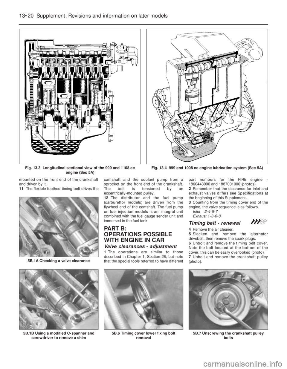
Valve clearances - adjustment
1The operations are similar to those
described in Chapter 1, Section 26, but note
that the special tools referred to have differentpart numbers for the FlRE engine -
1860443000 and 1887001000 (photos).
2Remember that the clearance for inlet and
exhaust valves differs see Specifications at
the beginning of this Supplement.
3Counting from the timing cover end of the
engine, the valve sequence is as follows.
Inlet 2-4-5-7
Exhaust 1-3-6-8
Timing belt - renewal #
4Remove the air cleaner.
5Slacken and remove the alternator
drivebelt, then remove the spark plugs.
6Unbolt and remove the timing belt cover.
Note the bolt located at the bottom of the
cover, this can be easily overlooked (photo).
7Unbolt and remove the crankshaft pulley
(photo).
13•20 Supplement: Revisions and information on later models
5B.7 Unscrewing the crankshaft pulley
bolts5B.6 Timing cover lower fixing bolt
removal5B.1B Using a modified C-spanner and
screwdriver to remove a shim
5B.1A Checking a valve clearance
Fig. 13.3 Longitudinal sectional view of the 999 and 1108 cc
engine (Sec 5A)Fig. 13.4 999 and 1008 cc engine lubrication system (Sec 5A)
Page 186 of 303
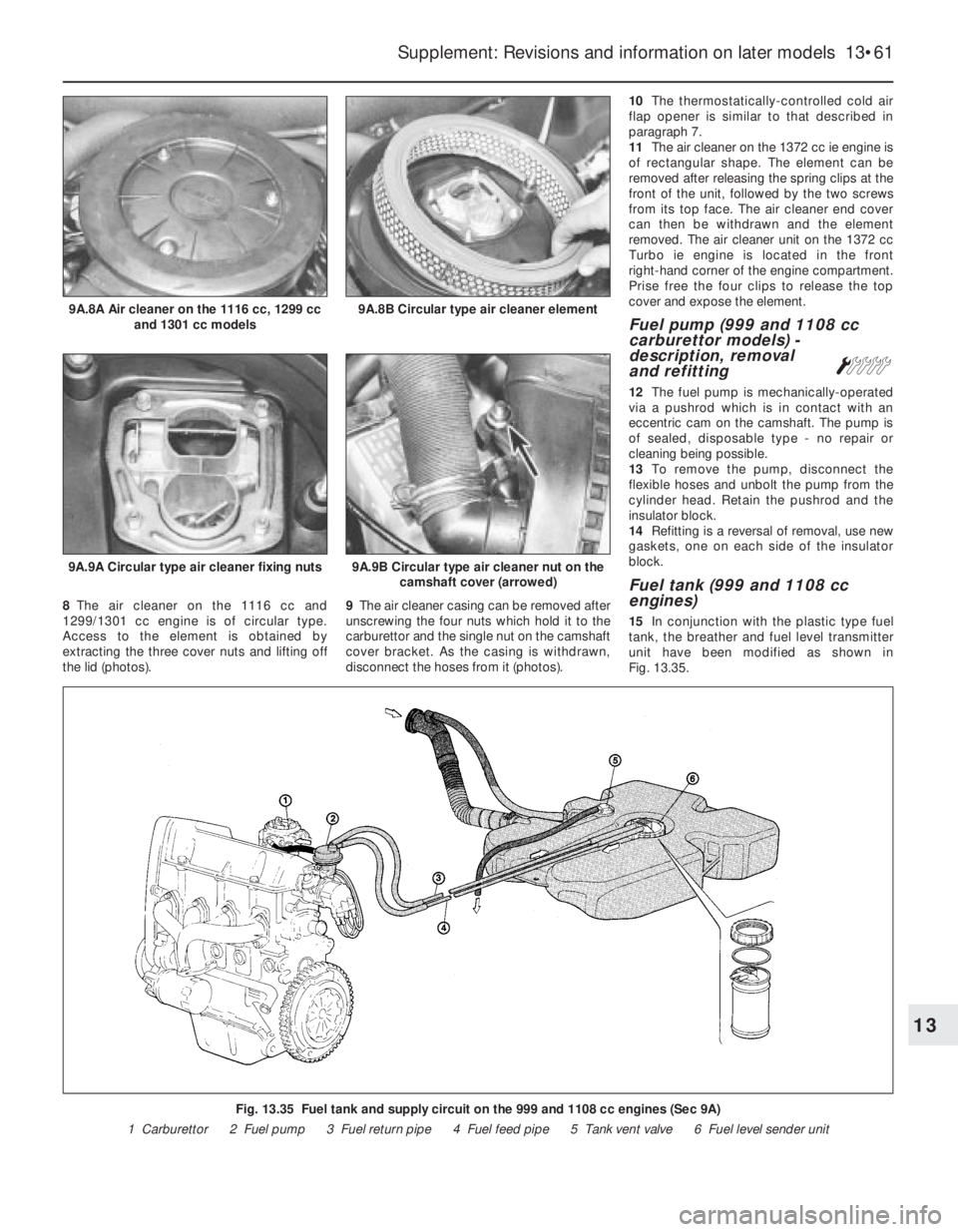
8The air cleaner on the 1116 cc and
1299/1301 cc engine is of circular type.
Access to the element is obtained by
extracting the three cover nuts and lifting off
the lid (photos).9The air cleaner casing can be removed after
unscrewing the four nuts which hold it to the
carburettor and the single nut on the camshaft
cover bracket. As the casing is withdrawn,
disconnect the hoses from it (photos).10The thermostatically-controlled cold air
flap opener is similar to that described in
paragraph 7.
11The air cleaner on the 1372 cc ie engine is
of rectangular shape. The element can be
removed after releasing the spring clips at the
front of the unit, followed by the two screws
from its top face. The air cleaner end cover
can then be withdrawn and the element
removed. The air cleaner unit on the 1372 cc
Turbo ie engine is located in the front
right-hand corner of the engine compartment.
Prise free the four clips to release the top
cover and expose the element.
Fuel pump (999 and 1108 cc
carburettor models) -
description, removal
and refitting
Á
12The fuel pump is mechanically-operated
via a pushrod which is in contact with an
eccentric cam on the camshaft. The pump is
of sealed, disposable type - no repair or
cleaning being possible.
13To remove the pump, disconnect the
flexible hoses and unbolt the pump from the
cylinder head. Retain the pushrod and the
insulator block.
14Refitting is a reversal of removal, use new
gaskets, one on each side of the insulator
block.
Fuel tank (999 and 1108 cc
engines)
15In conjunction with the plastic type fuel
tank, the breather and fuel level transmitter
unit have been modified as shown in
Fig. 13.35.
Supplement: Revisions and information on later models 13•61
9A.9A Circular type air cleaner fixing nuts9A.9B Circular type air cleaner nut on the
camshaft cover (arrowed)
9A.8B Circular type air cleaner element9A.8A Air cleaner on the 1116 cc, 1299 cc
and 1301 cc models
Fig. 13.35 Fuel tank and supply circuit on the 999 and 1108 cc engines (Sec 9A)
1 Carburettor 2 Fuel pump 3 Fuel return pipe 4 Fuel feed pipe 5 Tank vent valve 6 Fuel level sender unit
13
Page 191 of 303
adjustments described in this sub-Section,
however, will require removal of the
carburettor.
39Disconnect the short, curved diaphragm
hose from the top cover.
40Extract the top cover screws, lift the cover
from the carburettor body, and rotate it in
order to release the cranked choke control
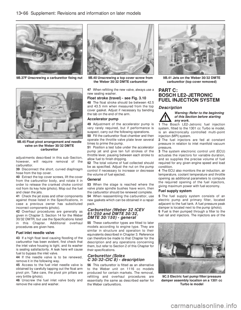
rod from its key hole (photo). Mop out the fuel
and clean the jets.
41Check the jet sizes and other components
against those listed in the Specifications, in
case a previous owner has substituted
incorrect components (photo).
42Overhaul procedures are generally as
given in Chapter 3, Section 14 for the Weber
30/32 DMTR, but use the Specifications listed
in this Chapter. Additional overhaul
procedures are given here.
Fuel inlet needle valve
43If a high float level causing flooding of the
carburettor has been evident, first check that
the inlet valve housing is tight, and its washer
is sealing satisfactorily. A leak here will cause
fuel to bypass the inlet valve.
44If the needle valve is to be renewed,
remove it in the following way.
45Access to the fuel inlet needle valve is
obtained by carefully tapping out the float arm
pivot pin. Take care, the pivot pin pillars are
very brittle (photo).
46Unscrew the fuel inlet valve body and
remove the valve and washer.47When refitting the new valve, always use a
new sealing washer.
Float stroke (travel) - see Fig. 3.10
48The float stroke should be between 42.5
and 43.5 mm when measured from the top
cover gasket. Adjust if necessary by bending
the tab on the end of the arm.
Accelerator pump
49Adjustment of the accelerator pump is
very rarely required, but if performance is
suspect, carry out the following operations.
50Fill the carburettor float chamber and then
operate the throttle valve plate lever several
times to prime the pump.
51Position a test tube under the accelerator
pump jet and give ten full strokes of the
throttle lever, pausing between each stroke to
allow fuel to finish dripping.
52The total volume of fuel collected should
be as specified. Adjust the nut on the pump
control if necessary to increase or decrease
the volume of fuel ejected.
General
53When the stage is reached where the
valve plate spindle bushes have worn, then
the carburettor should be renewed complete.
54When reassembling the carburettor, use
new gaskets which can be obtained in a repair
pack.
Carburettor (Weber 32 ICEV
61/250 and DMTE 30/32,
DMTE 30/150) - general
55These carburettor types are fitted to later
models according to engine type. They are
similar in structure and operation to their
equivalents described in Chapter 3. Reference
can therefore be made to that Chapter for the
description and any operations concerning
them, but refer to Section 2 of this Chapter for
their specifications.
Carburettor (Solex
C 30/32-CIC 8) - description
56This carburettor is fitted as an alternative
to the Weber unit on 1116 cc models
produced for certain markets. The removal,
refitting and overhaul procedures are
essentially the same as described earlier for
the Weber carburettors.
PART C:
BOSCH LE2-JETRONIC
FUEL INJECTION SYSTEM
Description
Warning: Refer to the beginning
of this Section before starting
any work.
1The Bosch LE2-Jetronic fuel injection
system, fitted to the 1301 cc Turbo ie model,
is an electronically controlled multi-point
injection (MPi) system.
2The fuel injectors are fed at constant
pressure in relation to inlet manifold vacuum
pressure.
3The system electronic control unit (ECU)
actuates the injectors for variable duration,
and so supplies the precise volume of fuel
required for any given engine speed and load
condition.
4The ECU also monitors the air induction, air
temperature, coolant temperature and throttle
opening as additional parameters to compute
the required opening of the fuel injectors,
giving maximum power with fuel economy.
Fuel supply system
5The fuel supply system consists of an
electric pump and primary filter, located
adjacent to the fuel tank. A fuel pressure peak
damper is located next to the pump (photo).
6Fuel is then pumped through a filter to the
fuel rail and injectors. The injectors are of the
13•66 Supplement: Revisions and information on later models
9C.5 Electric fuel pump/filter/pressure
damper assembly location on a 1301 cc
Turbo ie model
9B.41 Jets on the Weber 30/32 DMTE
carburettor (top cover removed)
9B.45 Float pivot arrangement and needle
valve on the Weber 30/32 DMTE
carburettor
9B.40 Unscrewing a top cover screw from
the Weber 30/32 DMTE carburettor9B.37F Unscrewing a carburettor fixing nut
Page 197 of 303
Throttle position switch
(potentiometer)
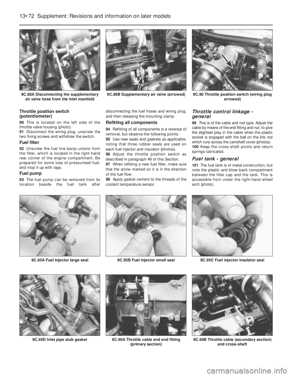
90This is located on the left side of the
throttle valve housing (photo).
91Disconnect the wiring plug, unscrew the
two fixing screws and withdraw the switch.
Fuel filter
92Unscrew the fuel line banjo unions from
the filter, which is located in the right-hand
rear corner of the engine compartment. Be
prepared for some loss of pressurised fuel,
and mop it up with rags.
Fuel pump
93The fuel pump can be removed from its
location beside the fuel tank afterdisconnecting the fuel hoses and wiring plug,
and then releasing the mounting clamp.
Refitting all components
94Refitting of all components is a reversal of
removal, but observe the following points.
95Use new seals and gaskets as applicable,
noting that three rubber seals are used on
each fuel injector and insulator (photos).
96Adjust the throttle position switch as
described in paragraph 46 of this Section.
97When refitting a new fuel filter, make sure
that the arrow marked on it is in the direction
of the fuel flow.
98Apply gasket cement to the threads of the
coolant temperature sensor.
Throttle control linkage -
general
99This is of the cable and rod type. Adjust the
cable by means of the end fitting and nut, to give
the slightest play in the cable when the plastic
socket is engaged with the ball on the link rod
which runs across the camshaft cover (photos).
100Keep the cross-shaft pivots and return
springs lubricated.
Fuel tank - general
101The fuel tank is of metal construction, but
note the plastic anti-blow-back compartment
between the filler cap and the tank. This is
accessible from under the right-hand wheel
arch (photo).
13•72 Supplement: Revisions and information on later models
9C.99B Throttle cable (secondary section)
and cross-shaft9C.99A Throttle cable and end fitting
(primary section)9C.95D Inlet pipe stub gasket
9C.95C Fuel injector insulator seal9C.95B Fuel injector small seal9C.95A Fuel injector large seal
9C.90 Throttle position switch (wiring plug
arrowed)9C.88B Supplementary air valve (arrowed)9C.88A Disconnecting the supplementary
air valve hose from the inlet manifold