roof rack FIAT UNO 1983 Service Repair Manual
[x] Cancel search | Manufacturer: FIAT, Model Year: 1983, Model line: UNO, Model: FIAT UNO 1983Pages: 303, PDF Size: 10.36 MB
Page 110 of 303
release its top coil from the strut upper
mounting, hold the flats on the strut spindle
and unscrew the spindle nut.
8Take off the upper mounting components
and the clamped coil spring. The clamps need
not be removed if the spring is to be fitted to a
new strut.
9Commence reassembly by fitting the coil
spring onto the strut. Make sure that the
smaller coil is at the top and the lower coil is
up against its end stop in the spring seat.
10Check that the strut boot is in position.
11Fit the upper mounting components and
screw on the spindle nut.
12Gently release the spring clamps and
remove them.
13Refit the strut to the car by reversing the
removal operations.
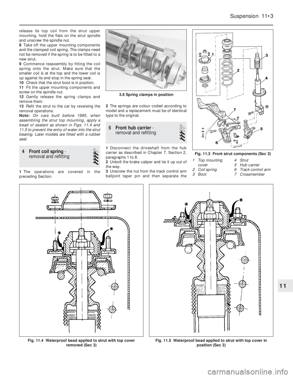
Note: On cars built before 1985, when
assembling the strut top mounting, apply a
bead of sealant as shown in Figs. 11.4 and
11.5 to prevent the entry of water into the strut
bearing. Later models are fitted with a rubber
seal.
4 Front coil spring-
removal and refitting
4
1The operations are covered in the
preceding Section.2The springs are colour coded according to
model and a replacement must be of identical
type to the original.
5 Front hub carrier-
removal and refitting
3
1Disconnect the driveshaft from the hub
carrier as described in Chapter 7, Section 2,
paragraphs 1 to 8.
2Unbolt the brake caliper and tie it up out of
the way.
3Unscrew the nut from the track control arm
balljoint taper pin and then separate the
Suspension 11•3
1 Top mounting
cover
2 Coil spring
3 Boot4 Strut
5 Hub carrier
6 Track control arm
7 Crossmember
Fig. 11.3 Front strut components (Sec 3)
3.6 Spring clamps in position
Fig. 11.4 Waterproof bead applied to strut with top cover
removed (Sec 3)Fig. 11.5 Waterproof bead applied to strut with top cover in
position (Sec 3)
11
Page 114 of 303
12
For dimensions, weights etc. refer to the Introductory Section of this Manual.
Chapter 12 Bodywork
For modifications, and information applicable to later models, see Supplement at end of manual
Bonnet - removal and refitting . . . . . . . . . . . . . . . . . . . . . . . . . . . . . 7
Bonnet - lock and release . . . . . . . . . . . . . . . . . . . . . . . . . . . . . . . . . 8
Centre console - removal and refitting . . . . . . . . . . . . . . . . . . . . . . . 21
Door - dismantling . . . . . . . . . . . . . . . . . . . . . . . . . . . . . . . . . . . . . . . 12
Door - removal and refitting . . . . . . . . . . . . . . . . . . . . . . . . . . . . . . . 13
Door trim panel - removal and refitting . . . . . . . . . . . . . . . . . . . . . . . 11
Facia panel - removal and refitting . . . . . . . . . . . . . . . . . . . . . . . . . . 22
Fixed side window (five-door) - removal and refitting . . . . . . . . . . . . 17
Front bumpers - removal and refitting . . . . . . . . . . . . . . . . . . . . . . . 9
Front seat - removal and refitting . . . . . . . . . . . . . . . . . . . . . . . . . . . 19
Front wing - removal and refitting . . . . . . . . . . . . . . . . . . . . . . . . . . . 10
General description . . . . . . . . . . . . . . . . . . . . . . . . . . . . . . . . . . . . . . 1
Grab handles . . . . . . . . . . . . . . . . . . . . . . . . . . . . . . . . . . . . . . . . . . . 25
Maintenance - bodywork and underframe . . . . . . . . . . . . . . . . . . . . 2Maintenance - upholstery and carpets . . . . . . . . . . . . . . . . . . . . . . . 3
Major body damage - repair . . . . . . . . . . . . . . . . . . . . . . . . . . . . . . . 5
Minor body damage - repair . . . . . . . . . . . . . . . . . . . . . . . . . . . . . . . 4
Opening side window (three-door) - removal and refitting . . . . . . . . 18
Radiator grille - removal and refitting . . . . . . . . . . . . . . . . . . . . . . . . 6
Rear bumpers - removal and refitting . . . . . . . . . . . . . . . . . . . . . . . . 26
Rear seat - removal and refitting . . . . . . . . . . . . . . . . . . . . . . . . . . . . 20
Rear view mirrors . . . . . . . . . . . . . . . . . . . . . . . . . . . . . . . . . . . . . . . 24
Roof rack . . . . . . . . . . . . . . . . . . . . . . . . . . . . . . . . . . . . . . . . . . . . . . 27
Seat belts . . . . . . . . . . . . . . . . . . . . . . . . . . . . . . . . . . . . . . . . . . . . . 23
Sunroof - operation and maintenance . . . . . . . . . . . . . . . . . . . . . . . 28
Tailgate - removal and refitting . . . . . . . . . . . . . . . . . . . . . . . . . . . . . 14
Tailgate glass - removal and refitting . . . . . . . . . . . . . . . . . . . . . . . . 16
Windscreen glass - removal and refitting . . . . . . . . . . . . . . . . . . . . . 15
12•1
Specifications Contents
Easy,suitable for
novice with little
experienceFairly easy,suitable
for beginner with
some experienceFairly difficult,
suitable for competent
DIY mechanic
Difficult,suitable for
experienced DIY
mechanicVery difficult,
suitable for expert DIY
or professional
Degrees of difficulty
54321
1 General description
The Uno is an all steel, welded Hatchback
of unitary construction available in three- or
five-door versions.
Various levels of trim and equipment are
available depending upon model.
Factory fitted options include a sunroof,
central door locking and electrically-operated
front windows.
2 Maintenance-
bodywork and underframe
1
The general condition of a vehicle’s
bodywork is the one thing that significantly
affects its value. Maintenance is easy, but
needs to be regular. Neglect, particularly after
minor damage, can lead quickly to further
deterioration and costly repair bills. It is
important also to keep watch on those parts
of the vehicle not immediately visible, for
instance the underside, inside all the wheel
arches, and the lower part of the engine
compartment.The basic maintenance routine for the
bodywork is washing - preferably with a lot of
water, from a hose. This will remove all the
loose solids which may have stuck to the
vehicle. It is important to flush these off in
such a way as to prevent grit from scratching
the finish. The wheel arches and underframe
need washing in the same way, to remove any
accumulated mud, which will retain moisture
and tend to encourage rust. Paradoxically
enough, the best time to clean the underframe
and wheel arches is in wet weather, when the
mud is thoroughly wet and soft. In very wet
weather, the underframe is usually cleaned of
large accumulations automatically, and this is
a good time for inspection.
Periodically, except on vehicles with a wax-
based underbody protective coating, it is a
good idea to have the whole of the
underframe of the vehicle steam-cleaned,
engine compartment included, so that a
thorough inspection can be carried out to see
what minor repairs and renovations are
necessary. Steam-cleaning is available at
many garages, and is necessary for the
removal of the accumulation of oily grime,
which sometimes is allowed to become thick
in certain areas. If steam-cleaning facilities are
not available, there are some excellent grease
solvents available which can be brush-applied; the dirt can then be simply hosed off.
Note that these methods should not be used
on vehicles with wax-based underbody
protective coating, or the coating will be
removed. Such vehicles should be inspected
annually, preferably just prior to Winter, when
the underbody should be washed down, and
any damage to the wax coating repaired.
Ideally, a completely fresh coat should be
applied. It would also be worth considering
the use of such wax-based protection for
injection into door panels, sills, box sections,
etc, as an additional safeguard against rust
damage, where such protection is not
provided by the vehicle manufacturer.
After washing paintwork, wipe off with a
chamois leather to give an unspotted clear
finish. A coat of clear protective wax polish
will give added protection against chemical
pollutants in the air. If the paintwork sheen
has dulled or oxidised, use a cleaner/polisher
combination to restore the brilliance of the
shine. This requires a little effort, but such
dulling is usually caused because regular
washing has been neglected. Care needs to
be taken with metallic paintwork, as special
non-abrasive cleaner/polisher is required to
avoid damage to the finish. Always check that
the door and ventilator opening drain holes
and pipes are completely clear, so that water
Page 124 of 303
24 Rear view mirrors
1
Interior
1The mirror may be removed after extracting
the fixing screws. The mirror is designed to
break off if struck.
Exterior
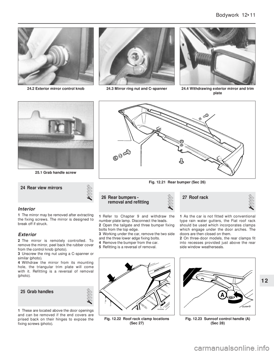
2The mirror is remotely controlled. To
remove the mirror, peel back the rubber cover
from the control knob (photo).
3Unscrew the ring nut using a C-spanner or
similar (photo).
4Withdraw the mirror from its mounting
hole, the triangular trim plate will come
with it. Refitting is a reversal of removal
(photo).
25 Grab handles
1
1These are located above the door openings
and can be removed if the end covers are
prised back on their hinges to expose the
fixing screws (photo).
26 Rear bumpers -
removal and refitting
1
1Refer to Chapter 9 and withdraw the
number plate lamp. Disconnect the leads.
2Open the tailgate and three bumper fixing
bolts from the top edge.
3Working under the car, remove the two side
and the three lower edge fixing bolts.
4Remove the bumper from the car.
5Refitting is a reversal of removal.
27 Roof rack
1
1As the car is not fitted with conventional
type rain water gutters, the Fiat roof rack
should be used which incorporates clamps
which engage under the door arches. The
doors are then closed on them.
2On three-door models, the rear clamps fit
into recesses provided just above the rear
side window weatherseals.
Bodywork 12•11
24.4 Withdrawing exterior mirror and trim
plate
25.1 Grab handle screw
24.3 Mirror ring nut and C-spanner24.2 Exterior mirror control knob
Fig. 12.23 Sunroof control handle (A)
(Sec 28)Fig. 12.22 Roof rack clamp locations
(Sec 27)
Fig. 12.21 Rear bumper (Sec 26)
12
Page 205 of 303
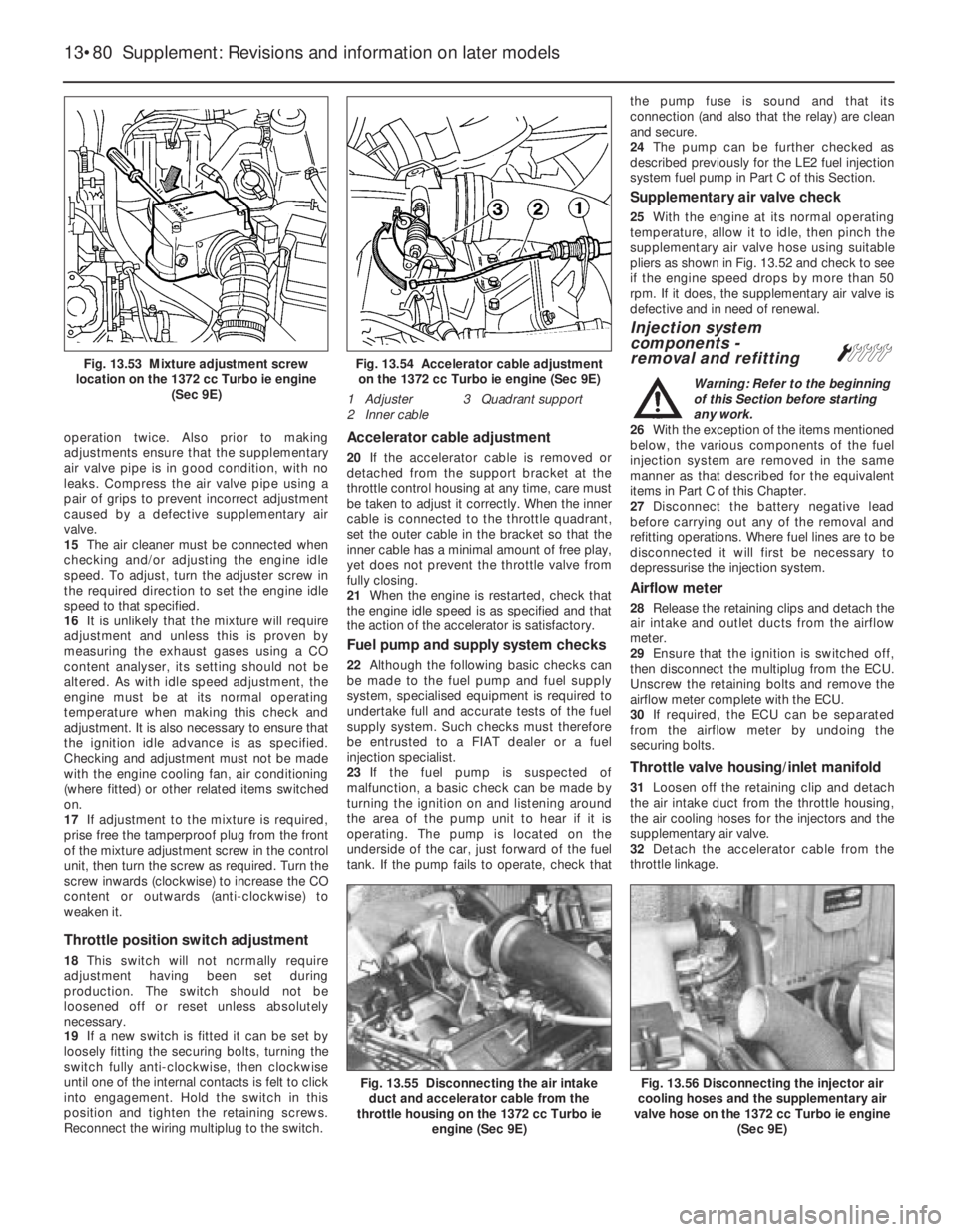
operation twice. Also prior to making
adjustments ensure that the supplementary
air valve pipe is in good condition, with no
leaks. Compress the air valve pipe using a
pair of grips to prevent incorrect adjustment
caused by a defective supplementary air
valve.
15The air cleaner must be connected when
checking and/or adjusting the engine idle
speed. To adjust, turn the adjuster screw in
the required direction to set the engine idle
speed to that specified.
16It is unlikely that the mixture will require
adjustment and unless this is proven by
measuring the exhaust gases using a CO
content analyser, its setting should not be
altered. As with idle speed adjustment, the
engine must be at its normal operating
temperature when making this check and
adjustment. It is also necessary to ensure that
the ignition idle advance is as specified.
Checking and adjustment must not be made
with the engine cooling fan, air conditioning
(where fitted) or other related items switched
on.
17If adjustment to the mixture is required,
prise free the tamperproof plug from the front
of the mixture adjustment screw in the control
unit, then turn the screw as required. Turn the
screw inwards (clockwise) to increase the CO
content or outwards (anti-clockwise) to
weaken it.
Throttle position switch adjustment
18This switch will not normally require
adjustment having been set during
production. The switch should not be
loosened off or reset unless absolutely
necessary.
19If a new switch is fitted it can be set by
loosely fitting the securing bolts, turning the
switch fully anti-clockwise, then clockwise
until one of the internal contacts is felt to click
into engagement. Hold the switch in this
position and tighten the retaining screws.
Reconnect the wiring multiplug to the switch.
Accelerator cable adjustment
20If the accelerator cable is removed or
detached from the support bracket at the
throttle control housing at any time, care must
be taken to adjust it correctly. When the inner
cable is connected to the throttle quadrant,
set the outer cable in the bracket so that the
inner cable has a minimal amount of free play,
yet does not prevent the throttle valve from
fully closing.
21When the engine is restarted, check that
the engine idle speed is as specified and that
the action of the accelerator is satisfactory.
Fuel pump and supply system checks
22Although the following basic checks can
be made to the fuel pump and fuel supply
system, specialised equipment is required to
undertake full and accurate tests of the fuel
supply system. Such checks must therefore
be entrusted to a FIAT dealer or a fuel
injection specialist.
23If the fuel pump is suspected of
malfunction, a basic check can be made by
turning the ignition on and listening around
the area of the pump unit to hear if it is
operating. The pump is located on the
underside of the car, just forward of the fuel
tank. If the pump fails to operate, check thatthe pump fuse is sound and that its
connection (and also that the relay) are clean
and secure.
24The pump can be further checked as
described previously for the LE2 fuel injection
system fuel pump in Part C of this Section.
Supplementary air valve check
25With the engine at its normal operating
temperature, allow it to idle, then pinch the
supplementary air valve hose using suitable
pliers as shown in Fig. 13.52 and check to see
if the engine speed drops by more than 50
rpm. If it does, the supplementary air valve is
defective and in need of renewal.
Injection system
components -
removal and refitting
Á
Warning: Refer to the beginning
of this Section before starting
any work.
26With the exception of the items mentioned
below, the various components of the fuel
injection system are removed in the same
manner as that described for the equivalent
items in Part C of this Chapter.
27Disconnect the battery negative lead
before carrying out any of the removal and
refitting operations. Where fuel lines are to be
disconnected it will first be necessary to
depressurise the injection system.
Airflow meter
28Release the retaining clips and detach the
air intake and outlet ducts from the airflow
meter.
29Ensure that the ignition is switched off,
then disconnect the multiplug from the ECU.
Unscrew the retaining bolts and remove the
airflow meter complete with the ECU.
30If required, the ECU can be separated
from the airflow meter by undoing the
securing bolts.
Throttle valve housing/inlet manifold
31Loosen off the retaining clip and detach
the air intake duct from the throttle housing,
the air cooling hoses for the injectors and the
supplementary air valve.
32Detach the accelerator cable from the
throttle linkage.
13•80 Supplement: Revisions and information on later models
Fig. 13.56 Disconnecting the injector air
cooling hoses and the supplementary air
valve hose on the 1372 cc Turbo ie engine
(Sec 9E)Fig. 13.55 Disconnecting the air intake
duct and accelerator cable from the
throttle housing on the 1372 cc Turbo ie
engine (Sec 9E)
Fig. 13.54 Accelerator cable adjustment
on the 1372 cc Turbo ie engine (Sec 9E)
1 Adjuster 3 Quadrant support
2 Inner cableFig. 13.53 Mixture adjustment screw
location on the 1372 cc Turbo ie engine
(Sec 9E)
Page 290 of 303
Tools and Working FacilitiesREF•7
REF
MImpact screwdriver
MMicrometer and/or vernier calipers (see
illustrations)
MDial gauge (see illustration)
MUniversal electrical multi-meter
MCylinder compression gauge
(see illustration)
MClutch plate alignment set (see
illustration)
MBrake shoe steady spring cup removal tool
(see illustration)
MBush and bearing removal/installation set
(see illustration)
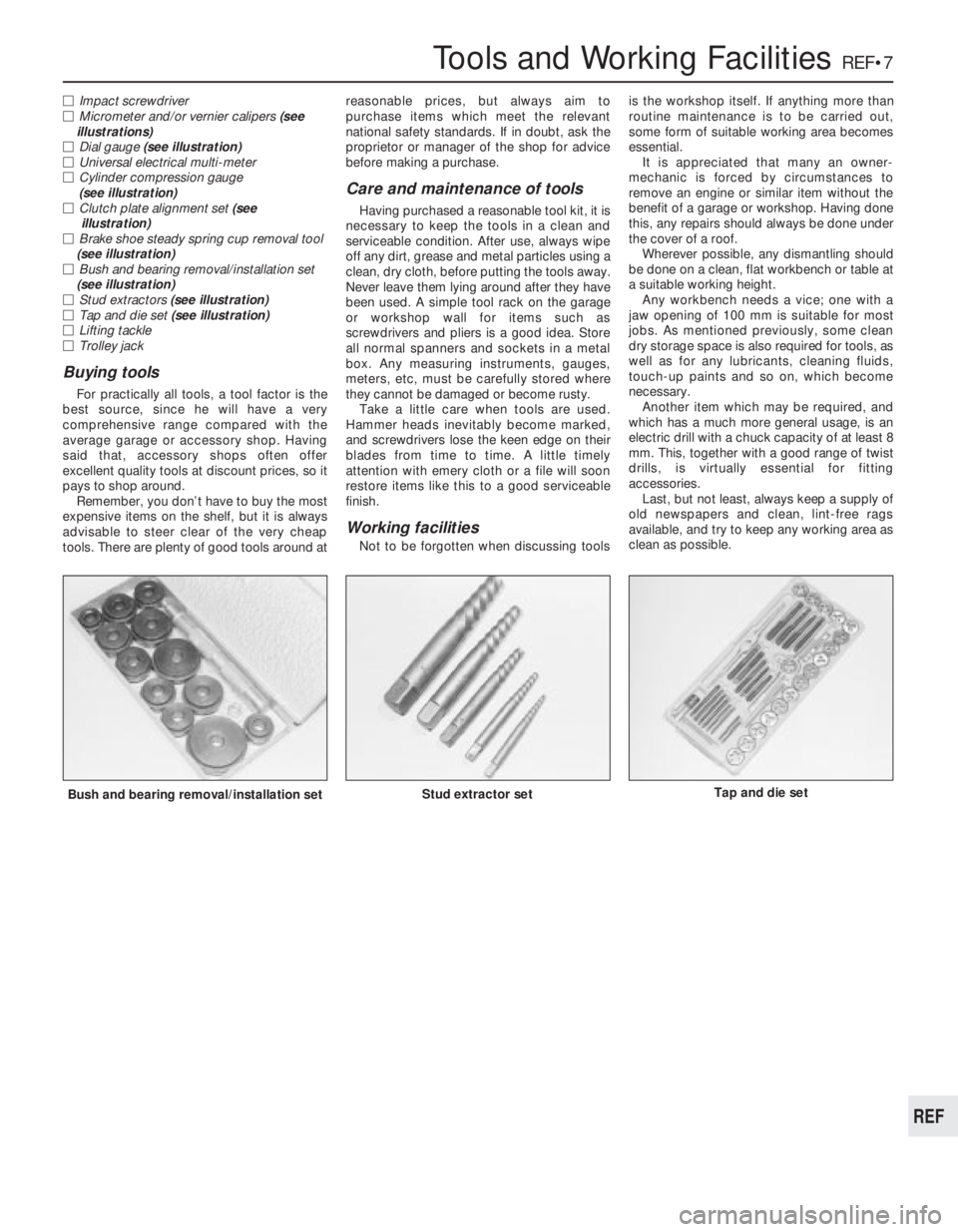
MStud extractors (see illustration)
MTap and die set (see illustration)
MLifting tackle
MTrolley jack
Buying tools
For practically all tools, a tool factor is the
best source, since he will have a very
comprehensive range compared with the
average garage or accessory shop. Having
said that, accessory shops often offer
excellent quality tools at discount prices, so it
pays to shop around.
Remember, you don’t have to buy the most
expensive items on the shelf, but it is always
advisable to steer clear of the very cheap
tools. There are plenty of good tools around atreasonable prices, but always aim to
purchase items which meet the relevant
national safety standards. If in doubt, ask the
proprietor or manager of the shop for advice
before making a purchase.
Care and maintenance of tools
Having purchased a reasonable tool kit, it is
necessary to keep the tools in a clean and
serviceable condition. After use, always wipe
off any dirt, grease and metal particles using a
clean, dry cloth, before putting the tools away.
Never leave them lying around after they have
been used. A simple tool rack on the garage
or workshop wall for items such as
screwdrivers and pliers is a good idea. Store
all normal spanners and sockets in a metal
box. Any measuring instruments, gauges,
meters, etc, must be carefully stored where
they cannot be damaged or become rusty.
Take a little care when tools are used.
Hammer heads inevitably become marked,
and screwdrivers lose the keen edge on their
blades from time to time. A little timely
attention with emery cloth or a file will soon
restore items like this to a good serviceable
finish.
Working facilities
Not to be forgotten when discussing toolsis the workshop itself. If anything more than
routine maintenance is to be carried out,
some form of suitable working area becomes
essential.
It is appreciated that many an owner-
mechanic is forced by circumstances to
remove an engine or similar item without the
benefit of a garage or workshop. Having done
this, any repairs should always be done under
the cover of a roof.
Wherever possible, any dismantling should
be done on a clean, flat workbench or table at
a suitable working height.
Any workbench needs a vice; one with a
jaw opening of 100 mm is suitable for most
jobs. As mentioned previously, some clean
dry storage space is also required for tools, as
well as for any lubricants, cleaning fluids,
touch-up paints and so on, which become
necessary.
Another item which may be required, and
which has a much more general usage, is an
electric drill with a chuck capacity of at least 8
mm. This, together with a good range of twist
drills, is virtually essential for fitting
accessories.
Last, but not least, always keep a supply of
old newspapers and clean, lint-free rags
available, and try to keep any working area as
clean as possible.
Bush and bearing removal/installation setStud extractor setTap and die set
Page 291 of 303
REF•8General Repair Procedures
Whenever servicing, repair or overhaul work
is carried out on the car or its components,
observe the following procedures and
instructions. This will assist in carrying out the
operation efficiently and to a professional
standard of workmanship.
Joint mating faces and gaskets
When separating components at their
mating faces, never insert screwdrivers or
similar implements into the joint between the
faces in order to prise them apart. This can
cause severe damage which results in oil
leaks, coolant leaks, etc upon reassembly.
Separation is usually achieved by tapping
along the joint with a soft-faced hammer in
order to break the seal. However, note that
this method may not be suitable where
dowels are used for component location.
Where a gasket is used between the mating
faces of two components, a new one must be
fitted on reassembly; fit it dry unless otherwise
stated in the repair procedure. Make sure that
the mating faces are clean and dry, with all
traces of old gasket removed. When cleaning a
joint face, use a tool which is unlikely to score
or damage the face, and remove any burrs or
nicks with an oilstone or fine file.
Make sure that tapped holes are cleaned
with a pipe cleaner, and keep them free of
jointing compound, if this is being used,
unless specifically instructed otherwise.
Ensure that all orifices, channels or pipes
are clear, and blow through them, preferably
using compressed air.
Oil seals
Oil seals can be removed by levering them
out with a wide flat-bladed screwdriver or
similar implement. Alternatively, a number of
self-tapping screws may be screwed into the
seal, and these used as a purchase for pliers or
some similar device in order to pull the seal free.
Whenever an oil seal is removed from its
working location, either individually or as part
of an assembly, it should be renewed.
The very fine sealing lip of the seal is easily
damaged, and will not seal if the surface it
contacts is not completely clean and free from
scratches, nicks or grooves. If the original
sealing surface of the component cannot be
restored, and the manufacturer has not made
provision for slight relocation of the seal
relative to the sealing surface, the component
should be renewed.
Protect the lips of the seal from any surface
which may damage them in the course of
fitting. Use tape or a conical sleeve where
possible. Lubricate the seal lips with oil before
fitting and, on dual-lipped seals, fill the space
between the lips with grease.
Unless otherwise stated, oil seals must be
fitted with their sealing lips toward the
lubricant to be sealed.
Use a tubular drift or block of wood of the
appropriate size to install the seal and, if the
seal housing is shouldered, drive the seal
down to the shoulder. If the seal housing isunshouldered, the seal should be fitted with
its face flush with the housing top face (unless
otherwise instructed).
Screw threads and fastenings
Seized nuts, bolts and screws are quite a
common occurrence where corrosion has set
in, and the use of penetrating oil or releasing
fluid will often overcome this problem if the
offending item is soaked for a while before
attempting to release it. The use of an impact
driver may also provide a means of releasing
such stubborn fastening devices, when used
in conjunction with the appropriate
screwdriver bit or socket. If none of these
methods works, it may be necessary to resort
to the careful application of heat, or the use of
a hacksaw or nut splitter device.
Studs are usually removed by locking two
nuts together on the threaded part, and then
using a spanner on the lower nut to unscrew
the stud. Studs or bolts which have broken off
below the surface of the component in which
they are mounted can sometimes be removed
using a stud extractor. Always ensure that a
blind tapped hole is completely free from oil,
grease, water or other fluid before installing
the bolt or stud. Failure to do this could cause
the housing to crack due to the hydraulic
action of the bolt or stud as it is screwed in.
When tightening a castellated nut to accept
a split pin, tighten the nut to the specified
torque, where applicable, and then tighten
further to the next split pin hole. Never slacken
the nut to align the split pin hole, unless stated
in the repair procedure.
When checking or retightening a nut or bolt
to a specified torque setting, slacken the nut
or bolt by a quarter of a turn, and then
retighten to the specified setting. However,
this should not be attempted where angular
tightening has been used.
For some screw fastenings, notably
cylinder head bolts or nuts, torque wrench
settings are no longer specified for the latter
stages of tightening, “angle-tightening” being
called up instead. Typically, a fairly low torque
wrench setting will be applied to the
bolts/nuts in the correct sequence, followed
by one or more stages of tightening through
specified angles.
Locknuts, locktabs and washers
Any fastening which will rotate against a
component or housing during tightening
should always have a washer between it and
the relevant component or housing.
Spring or split washers should always be
renewed when they are used to lock a critical
component such as a big-end bearing
retaining bolt or nut. Locktabs which are
folded over to retain a nut or bolt should
always be renewed.
Self-locking nuts can be re-used in non-
critical areas, providing resistance can be felt
when the locking portion passes over the bolt
or stud thread. However, it should be noted
that self-locking stiffnuts tend to lose theireffectiveness after long periods of use, and
should then be renewed as a matter of course.
Split pins must always be replaced with
new ones of the correct size for the hole.
When thread-locking compound is found
on the threads of a fastener which is to be re-
used, it should be cleaned off with a wire
brush and solvent, and fresh compound
applied on reassembly.
Special tools
Some repair procedures in this manual
entail the use of special tools such as a press,
two or three-legged pullers, spring com-
pressors, etc. Wherever possible, suitable
readily-available alternatives to the manu-
facturer’s special tools are described, and are
shown in use. In some instances, where no
alternative is possible, it has been necessary
to resort to the use of a manufacturer’s tool,
and this has been done for reasons of safety
as well as the efficient completion of the repair
operation. Unless you are highly-skilled and
have a thorough understanding of the
procedures described, never attempt to
bypass the use of any special tool when the
procedure described specifies its use. Not
only is there a very great risk of personal
injury, but expensive damage could be
caused to the components involved.
Environmental considerations
When disposing of used engine oil, brake
fluid, antifreeze, etc, give due consideration to
any detrimental environmental effects. Do not,
for instance, pour any of the above liquids
down drains into the general sewage system,
or onto the ground to soak away. Many local
council refuse tips provide a facility for waste
oil disposal, as do some garages. If none of
these facilities are available, consult your local
Environmental Health Department, or the
National Rivers Authority, for further advice.
With the universal tightening-up of legis-
lation regarding the emission of environmen-
tally-harmful substances from motor vehicles,
most vehicles have tamperproof devices fitted
to the main adjustment points of the fuel
system. These devices are primarily designed
to prevent unqualified persons from adjusting
the fuel/air mixture, with the chance of a
consequent increase in toxic emissions. If
such devices are found during servicing or
overhaul, they should, wherever possible, be
renewed or refitted in accordance with the
manufacturer’s requirements or current
legislation.
Note: It is
antisocial and
illegal to dump
oil down the
drain. To find
the location of
your local oil
recycling
bank, call this
number free.
Page 301 of 303
F
Facia - 12•10, 13•107
Fan -2•3, 13•57, 13•71, 13•84
Fast idle adjustment -3•7, 3•9, 3•10, 3•11,
13•64
Fault finding- REF`•9et seq
Fault finding - braking system -8•9
Fault finding - clutch -5•3
Fault finding - cooling and heating systems
-2•8
Fault finding - driveshafts and hubs -7•6
Fault finding - Econometer -9•12
Fault finding - electrical system -9•14,
REF•9
Fault finding - engine -1•35, 1•36, 2•8,
3•13, 4•9, 13•92, REF•10, REF•11
Fault finding - fuel system -3•9, 3•13,
13•84
Fault finding - ignition system -4•9,
REF•11
Fault finding - Microplex ignition system -
13•92
Fault finding - steering - 10•4
Fault finding - suspension - 11•6
Fault finding - transmission -6•4
Fault finding - turbocharger system - 13•84
Filling - 12•3
Final drive output shafts - 13•94
Fire -0•5
Float adjustment -3•7, 3•8, 3•10, 3•11,
13•64, 13•66
Flywheel -1•19, 1•21, 1•31, 13•46, 13•53
Fog lamps - 13•106
Fuel evaporation control system - 13•78
Fuel filter - 13•67, 13•72, 13•74, 13•79
Fuel gauge fault -9•14
Fuel injection electronic control unit (ECU)
- 13•77
Fuel injection system - 13•68, 13•69
Fuel injection system fault finding - 13•84
Fuel injectors - 13•69, 13•70, 13•71, 13•76,
13•77, 13•81, 13•84
Fuel level transmitter -3•5
Fuel pressure regulator - 13•70
Fuel pump -3•5, 13•61, 13•69, 13•72,
13•76, 13•80, 13•81
Fuel rail - 13•70, 13•81
Fuel system-3•1et seq, 13•60, REF•4
Fuel system fault finding -3•9, 3•13
Fuel tank -3•5, 13•61, 13•72
Fume or gas intoxication -0•5
Fuses -9•5, 13•105
G
Gaiters -7•2, 10•2, 13•98
Gashes in bodywork - 12•2
Gaskets -1•20
Gearbox - SeeTransmission
Gearchange lever -6•2
Gearchange linkage - 13•94, 13•95
Glossary of technical terms- REF•13et seq
Grille - 12•3, 13•113
H
Handbrake -8•8, 8•9, REF•1
Handles - 12•11
HC emissions - REF•4
Headlamp -9•6, 9•7, 13•105, 13•106
Heated tailgate window -9•10
Heater -2•5, 2•6, 13•58, 13•59, 13•108
Heater fault -2•8
Horn -9•6, 13•106
Horn fault -9•14
HT leads - 13•92
Hubs -7•3, 7•4, 11•3
Hydraulic hoses and pipes -8•6
Hydraulic system -8•7
Hydrofluoric acid -0•5
I
Idle speed adjustment -3•7, 13•62, 13•65,
13•68, 13•75, 13•79
Idling fault -1•36, 3•13, 13•84
Ignition coil - 13•86, 13•90, 13•91
Ignition switch -4•8
Ignition system-4•1et seq, 13•85
Ignition system fault finding -4•9, 9•14,
REF•11
Ignition unit - 13•89
Indicators -9•7
Injectors - 13•69, 13•70, 13•71, 13•76,
13•77, 13•81, 13•84
Inlet manifold - 13•70, 13•77, 13•80
Instrument panel -9•8, 13•107
Intercooler - 13•84
Interior lamps -9•5, 9•8
Introduction to the Fiat Uno -0•4
J
Jacking -0•8
Joint mating faces and gaskets - REF•8
Jump starting -0•7
L
Lambda sensor - 13•82
Lamps -9•6, 9•7, 9•8
Leaks -0•9, 1•36, 13•84
LED (light emitter diode) -9•12
Lights fault -9•14
Locknuts,locktabs and washers - REF•8
Locks -9•11, 10•4, 12•4, 12•6, 12•7,
13•109
Loudspeakers -9•11
Lubricants and fluids -0•13
M
Magnetic impulse generator winding -
13•86
Main bearings -1•20, 1•30, 13•52
Maintenance -0•10, 13•18
Manifolds -3•12, 13•70, 13•77, 13•80
Master cylinder -8•5, 13•103, 13•93
Microplex ignition system - 13•86, 13•89Microplex ignition system fault finding -
13•92
Mirrors - 12•11, 13•111, REF•1
Misfire -1•35, 4•9, REF•11
Mixture adjustment -3•7, 13•62, 13•65,
13•68, 13•75, 13•79
MOT test checks- REF•1et seq
Mountings -1•13, 1•27, 13•26, 13•35,
13•49
N
Needle valve - 13•66
Number plate lamp -9•7
O
Oil cooler - 13•36
Oil filter -1•8
Oil level sensor - 13•110, 13•111
Oil pressure fault -1•36, REF•11
Oil pump -1•13, 1•19, 1•22, 1•26, 1•29,
13•24, 13•30, 13•35, 13•46, 13•53
Oil seals -1•20, 13•41, 13•44, 13•45,
13•94, REF•8
Oil,engine -0•6, 0•13, 1•3, 1•4, 1•8
Oil,transmission -0•6, 0•13, 6•1, 13•14,
13•95
Overheating -2•8, 4•9, REF•11
P
Pad wear sensor - 13•110
Pads -8•2, 13•100, 13•101
Parking lamp -9•7
Pedals -5•2, 8•9, 13•92, 13•102
Pinking -1•36, 13•84, REF•11
Pistons -1•12, 1•18, 1•22, 1•26, 1•30,
13•25, 13•26, 13•30, 13•35, 13•47,
13•48, 13•53
Plastic components - 13•111
Points -4•2, 4•3
Poisonous or irritant substances -0•5
Power module - 13•90
Pre-ignition -1•36, 13•84, REF•11
Pressure regulating valve -8•6, 13•102
Pressure sensor - 13•86
R
Radiator -2•3, 12•3, 13•57, 13•113
Radio -9•10, 13•110
Rear lamp cluster -9•7
Regulator (voltage) -9•4
Regulator (window) - 12•7
Relays -9•5, 13•71, 13•105
Repair procedures - REF•8
Respraying - 12•3
Rocker cover - 13•19
Rockers -1•19
Roof rack - 12•11
Routine maintenance -0•10, 13•18
Rust holes in bodywork - 12•2
REF•18Index
Page 302 of 303
S
Safety first -0•5
Safety pressure switch - 13•90
Scalding -0•5
Scratches in bodywork - 12•2
Screw threads and fastenings - REF•8
Seat belts - 12•10, REF•2
Seats - 12•9, REF•2
Servo unit -8•8, 13•103
Shock absorbers - 11•4, REF•2, REF•3
Shoes -8•3
Side light -9•7
Side repeater lamp -9•7
Spares - REF•10, REF•12
Spark plugs -4•7, 13•92
Speedometer -9•8
Spotlamp - 13•108
Springs - 11•3, 11•4, REF•3
Starter motor -9•4, 13•104, 13•105
Starter fault -1•35, 9•14, 13•92, REF•10
Steering-9•5, 10•1et seq, 13•106, REF•1,
REF•2, REF•3
Steering fault finding - 10•4
Stop lamp switch -8•9
Struts - 11•2, 13•111
Sump -1•11, 1•22, 1•26, 1•31, 13•19,
13•24, 13•46, 13•53
Sunroof - 12•12
Supplement: Revisions and information on
later models- 13•1et seq
Supplementary air valve - 13•67, 13•69,
13•71, 13•80
Suspension- 11•1et seq, 13•111, REF•2,
REF•3
Suspension fault finding - 11•6
Switches -2•3, 4•8, 8•9, 9•5, 13•69, 13•72,
13•80, 13•90, 13•106 to 13•109
T
Tailgate -9•6, 12•8, 12•9, 13•112
TDC sensor -4•7, 13•90, 13•91
Thermostat -2•3, 13•54, 13•57
Throttle control linkage - 13•72
Throttle position switch - 13•69, 13•72,
13•80
Throttle valve housing - 13•67, 13•70,
13•80
Tie-rod - 10•2
Timing -4•4, 13•85, 13•91
Timing belt -1•24, 1•29, 1•32, 13•20,
13•30, 13•35, 13•38, 13•53
Timing chain -1•9, 1•19, 1•22
Tools - REF•5, REF•7, REF•8, REF•10
Towing -0•8
Track control arm - 11•4
Trailing arms - 11•5
Transmission-1•13, 1•22, 1•27, 1•32, 6•1
et seq, 13•26, 13•33, 13•36, 13•49,
13•53, 13•94, 13•96
Transmission fault finding -6•4
Transmission oil -0•6, 0•13, 6•1, 13•14,
13•95
Trim panels - 12•5, 13•114
Trip master - 13•108
Tripode joint -7•3
Turbocharger - 13•82, 13•83
Turbocharger fault finding - 13•84
Tyres -7•5, 10•4, 11•6, REF•4
U
Underframe - 12•1
Unleaded fuel - 13•60
Upholstery - 12•2
V
Vacuum sensor - 13•86
Vacuum servo -8•8, 13•103
Valve clearances -1•9, 1•23, 1•32, 13•20,
13•37
Vehicle identification - REF•2, REF•12
Voltage regulator -9•4
W
Washer system -9•10, 13•110
Water pump -2•4, 13•55, 13•58
Weights -0•6, 13•17
Wheel alignment - 10•3
Wheel bearings -7•3, 7•4, REF•3
Wheel changing -0•8
Wheel cylinder -8•4
Wheels -7•5, REF•4
Window regulator - 12•7
Windows -9•11, 12•6, 12•9, 13•109,
13•113
Windscreen - 12•8, REF•1
Wings - 12•5
Wiper blade and arm -9•9
Wiper motor -9•9, 9•10, 13•109, 13•110
Wiper fault -9•14
Wiring diagrams- 14•1et seq
Working facilities - REF•7
IndexREF•19
REF