ECU FORD C MAX 2008 1.G User Guide
[x] Cancel search | Manufacturer: FORD, Model Year: 2008, Model line: C MAX, Model: FORD C MAX 2008 1.GPages: 278, PDF Size: 17.5 MB
Page 132 of 278
Downloaded from www.Manualslib.com manuals search engine Vehicles with seat supports
Slide the supports into the larger holeon the base of the seats and detachthem. Fold the outboard seatsupports down and attach them tothe retainers on the floor. Detach thecentre seat support from the floorand secure it in its retainer on thefloor under the right-hand seat.
All vehicles
WARNING
Make sure the seat is securelylocked by pushing forward andrearward on the top of the seatbackor by trying to pull up the edge of thecushion.
Fold the seats back down until theyengage.
Raise the seatbacks ensuring thatthey engage in their latches.
Make sure the seatbelts will functionproperly and are positioned in frontof the seatback.
The rear seatbelts should be placedin the belt guides on the outboardseatbacks.
Removing the seats
To increase the space in the luggagecompartment, the rear seats can beremoved completely.
Fold the seats forward. See Foldingthe seats forward.
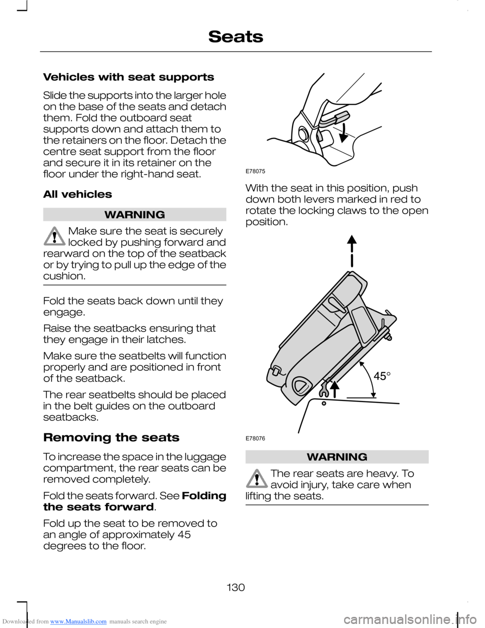
Fold up the seat to be removed toan angle of approximately 45degrees to the floor.
With the seat in this position, pushdown both levers marked in red torotate the locking claws to the openposition.
WARNING
The rear seats are heavy. Toavoid injury, take care whenlifting the seats.
130
SeatsE78075 E78076
Page 137 of 278
Downloaded from www.Manualslib.com manuals search engine CAUTIONS
Do not exceed the maximumpower output. If you do, the LEDwill flash twice. Remove the plug andre-insert it.
If the LED flashes 3 or 4 times,have the system checked by aproperly trained technician.
CENTRE CONSOLE
Front seat centre console
WARNINGS
Do not place hot drinks in thecup holders when the vehicle ismoving.
Do not use the rear storagecompartment as an ashtray.
The following features areincorporated into the centre console:
•Front and rear storagecompartments.
•Ashtray. To empty, pull out thecomplete ashtray.
•Cigar lighter. See Cigar lighter(page 134).
•Cup holders.
•Auxiliary input (AUX IN) socket.See Auxiliary input (AUX IN)socket (page 140).
•Storage box.
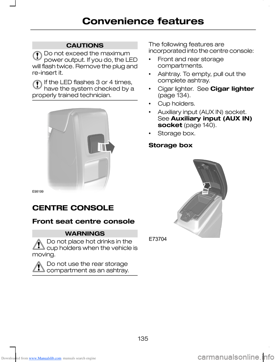
Storage box
135
Convenience featuresE98199 E73704
Page 140 of 278
Downloaded from www.Manualslib.com manuals search engine WARNING
Never drive with the frontstorage compartment lid open.This will obscure your vision out ofthe windscreen. Before setting off,always ensure that the lid is securelyengaged.
Note:Avoid keeping heat-sensitiveobjects and liquids in the frontstorage compartment.
Driver’s seat storage bin
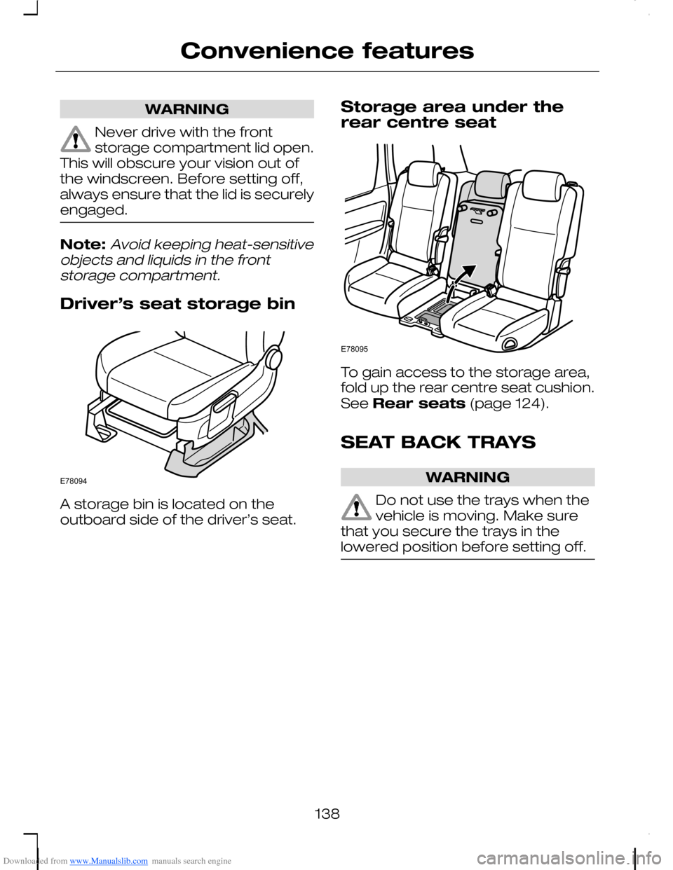
A storage bin is located on theoutboard side of the driver’s seat.
Storage area under therear centre seat
To gain access to the storage area,fold up the rear centre seat cushion.See Rear seats (page 124).
SEAT BACK TRAYS
WARNING
Do not use the trays when thevehicle is moving. Make surethat you secure the trays in thelowered position before setting off.
138
Convenience featuresE78094 E78095
Page 169 of 278
Downloaded from www.Manualslib.com manuals search engine GENERAL INFORMATION
WARNINGS
Use load securing straps to anapproved standard, e.g. DIN.
Make sure that you secure allloose items properly.
Place luggage and other loadsas low and as far forward aspossible within the luggage orloadspace.
Do not drive with the tailgate orrear door open. Exhaust fumesmay enter the vehicle.
Do not exceed the maximumfront and rear axle loads for yourvehicle. See Vehicleidentification (page 226).
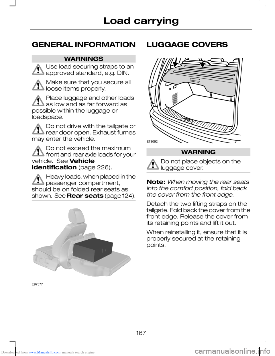
Heavy loads, when placed in thepassenger compartment,should be on folded rear seats asshown. See Rear seats (page 124).
LUGGAGE COVERS
WARNING
Do not place objects on theluggage cover.
Note:When moving the rear seatsinto the comfort position, fold backthe cover from the front edge.
Detach the two lifting straps on thetailgate. Fold back the cover from thefront edge. Release the cover fromits retaining points and lift it out.
When reinstalling it, ensure that it isproperly secured at the retainingpoints.
167
Load carryingE97377 E78092
Page 171 of 278
Downloaded from www.Manualslib.com manuals search engine TOWING A TRAILER
WARNINGS
Do not exceed the maximumvehicle and trailer weight statedon the vehicle identification plate. SeeVehicle identification (page 226).
ST vehicles are not approvedfor trailer towing.
Note:Not all vehicles are suitable orapproved to have tow bars fitted.Check with your dealer first.
Place loads as low and central to theaxle(s) of the trailer as possible. If youare towing with an unladen vehicle,the load in the trailer should beplaced toward the nose, within themaximum nose load, as this gives thebest stability.
Note:The maximum trailer noseweight can be found on themanufacturers data plate on the towbar.
The stability of the vehicle to trailercombination is very much dependanton the quality of the trailer.
In high altitude regions, the stipulatedmaximum permitted gross trainweight must be reduced by 10% forevery 1 000 metres (3 281 feet).
Steep gradients
WARNING
The overrun brake on a trailer isnot controlled by ABS.
Change down a gear before youreach a steep downhill gradient.
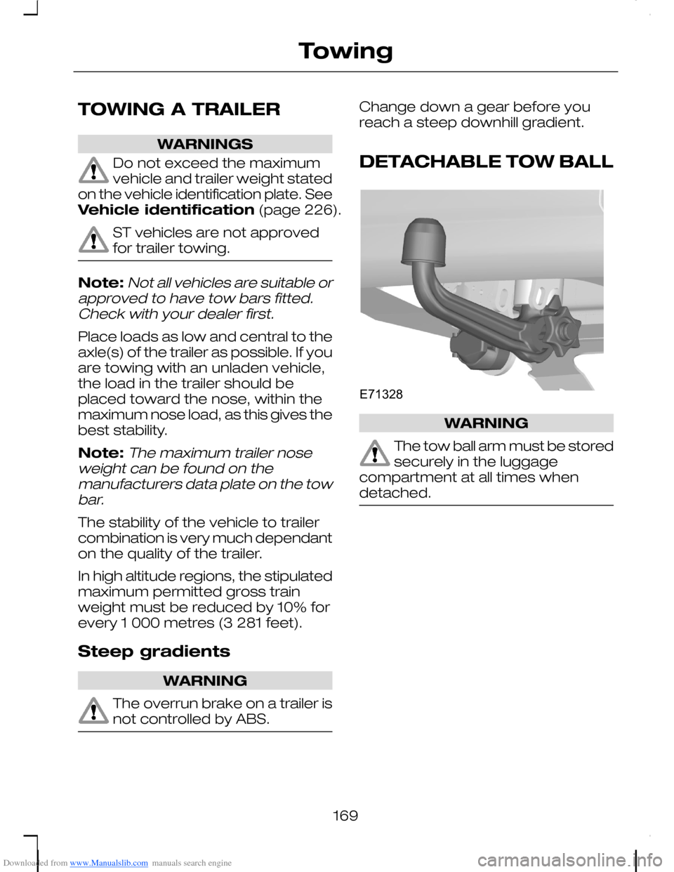
DETACHABLE TOW BALL
WARNING
The tow ball arm must be storedsecurely in the luggagecompartment at all times whendetached.
169
TowingE71328
Page 173 of 278
Downloaded from www.Manualslib.com manuals search engine 1.Insert the tow ball arm verticallyand press it upwards until itengages. Do not hold your handnear the handwheel.
2.To lock: Turn the key clockwiseand remove the key.
Insert the end of the protection capinto the keyhole.
Driving with a trailer
WARNING
If any of the below conditionscannot be met, do not use thetow bar and have it inspected by anexpert.
Before starting your journey, ensurethe tow ball arm is properly locked.Check that:
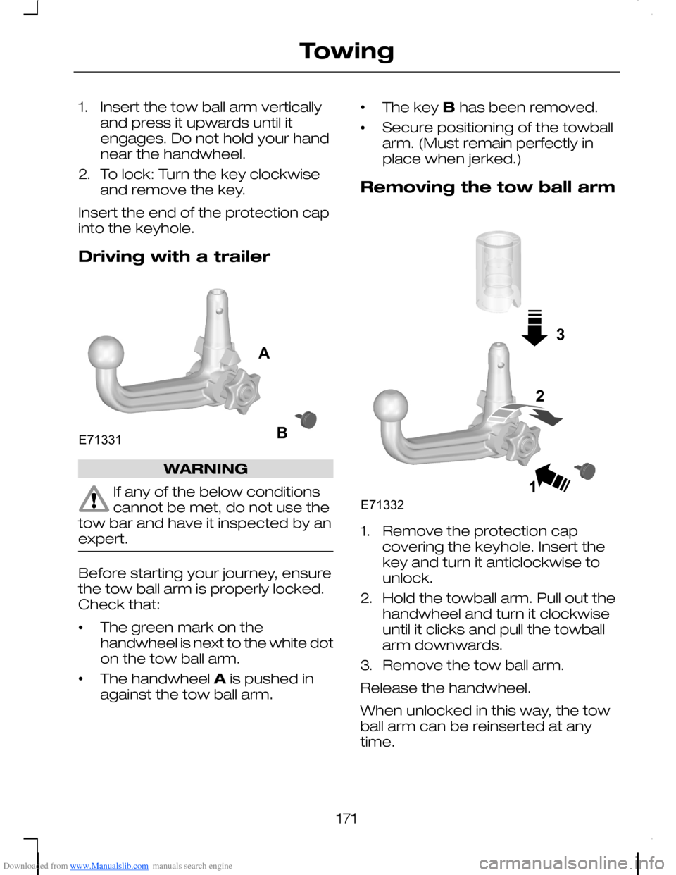
•The green mark on thehandwheel is next to the white doton the tow ball arm.
•The handwheel A is pushed inagainst the tow ball arm.
•The key B has been removed.
•Secure positioning of the towballarm. (Must remain perfectly inplace when jerked.)
Removing the tow ball arm
1.Remove the protection capcovering the keyhole. Insert thekey and turn it anticlockwise tounlock.
2.Hold the towball arm. Pull out thehandwheel and turn it clockwiseuntil it clicks and pull the towballarm downwards.
3.Remove the tow ball arm.
Release the handwheel.
When unlocked in this way, the towball arm can be reinserted at anytime.
171
TowingE71331AB 31E713322
Page 205 of 278
Downloaded from www.Manualslib.com manuals search engine If it drops below the MIN mark, topup with the specified fluid. SeeTechnical specifications (page204).
Vehicles with 1.8L Duratec-HE (MI4) or 2.0L Duratec-HE (MI4) or 2.5L Duratec-ST (VI5) or 1.6L Duratorq-TDCi (DV) Diesel or 1.8LDuratorq-TDCi (Kent) Dieselor 2.0L Duratorq-TDCi(Kent) Diesel engine
No fluid level checks are necessary.
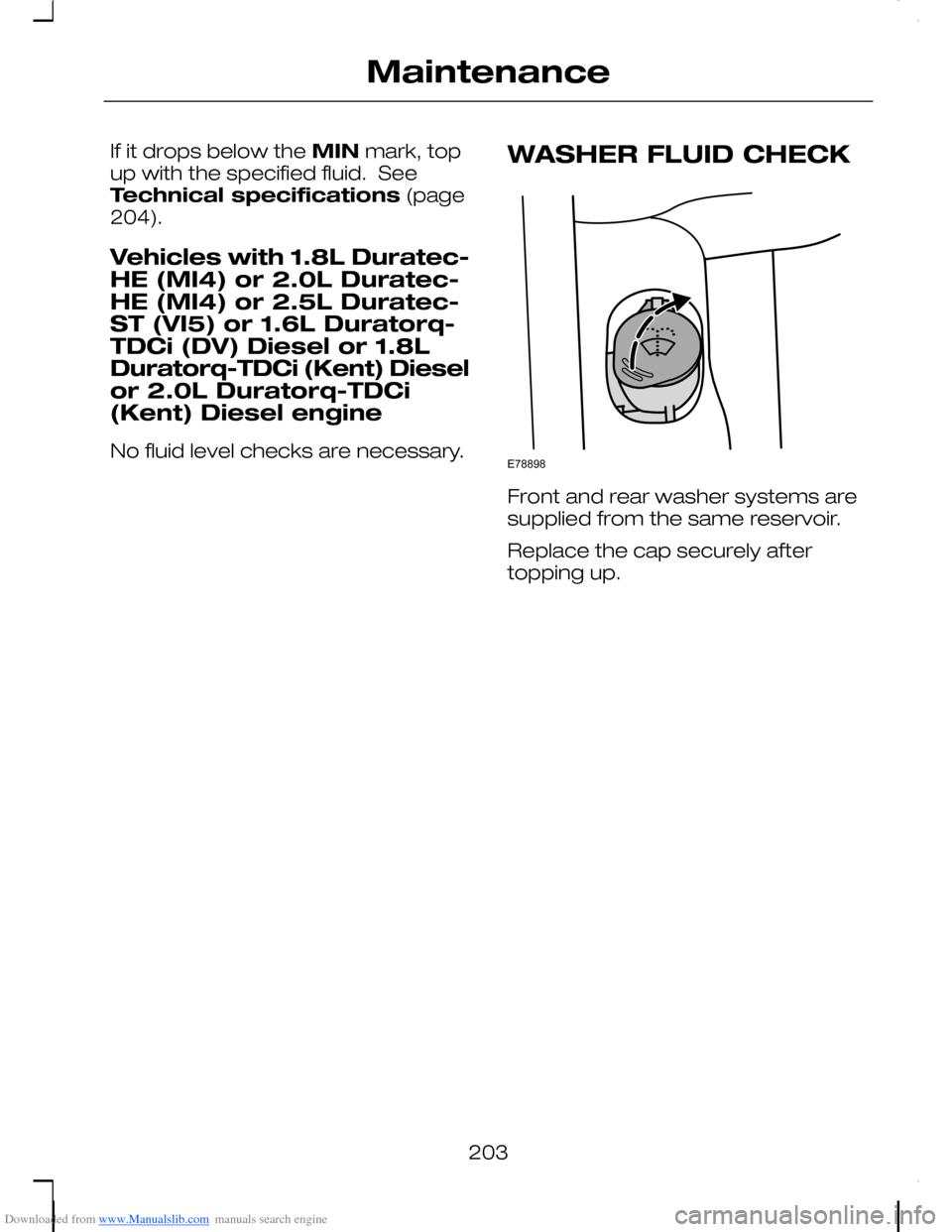
WASHER FLUID CHECK
Front and rear washer systems aresupplied from the same reservoir.
Replace the cap securely aftertopping up.
203
MaintenanceE78898
Page 217 of 278
Downloaded from www.Manualslib.com manuals search engine Removing a wheel
All vehicles
WARNINGS
Park your vehicle in such aposition that neither the trafficnor you are hindered or endangered.
Set up a warning triangle.
Make sure that the vehicle is onfirm, level ground with thewheels pointing straight ahead.
WARNINGS
Switch off the ignition and applythe parking brake.
If your vehicle has a manualtransmission, select first orreverse gear. If it has an automatictransmission, select park.
Have the passengers leave thevehicle.
Secure the diagonally oppositewheel with an appropriate blockor wheel chock.
Make sure that the arrows ondirectional tyres point in thedirection of rotation when the vehicleis moving forwards. If you have to fita spare wheel with the arrowspointing in the opposite direction,have the tyre refitted in the correctdirection by a properly trainedtechnician.
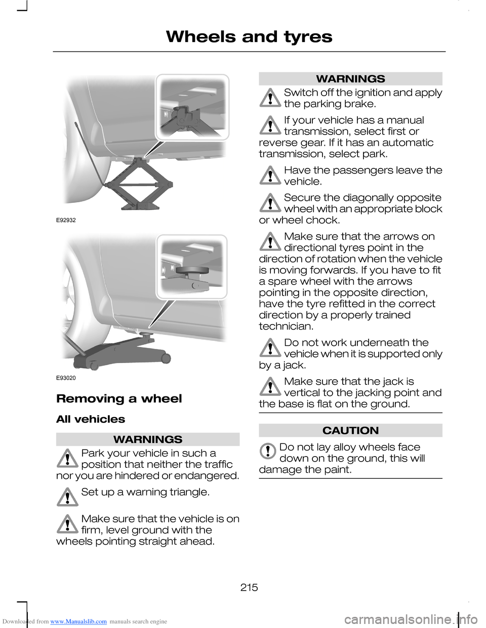
Do not work underneath thevehicle when it is supported onlyby a jack.
Make sure that the jack isvertical to the jacking point andthe base is flat on the ground.
CAUTION
Do not lay alloy wheels facedown on the ground, this willdamage the paint.
215
Wheels and tyresE92932 E93020
Page 218 of 278
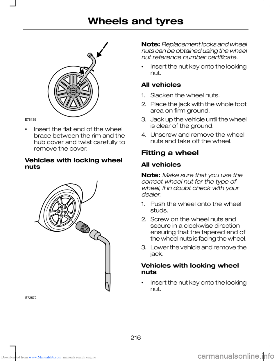
Downloaded from www.Manualslib.com manuals search engine •Insert the flat end of the wheelbrace between the rim and thehub cover and twist carefully toremove the cover.
Vehicles with locking wheelnuts
Note:Replacement locks and wheelnuts can be obtained using the wheelnut reference number certificate.
•Insert the nut key onto the lockingnut.
All vehicles
1.Slacken the wheel nuts.
2.Place the jack with the whole footarea on firm ground.
3.Jack up the vehicle until the wheelis clear of the ground.
4.Unscrew and remove the wheelnuts and take off the wheel.
Fitting a wheel
All vehicles
Note:Make sure that you use thecorrect wheel nut for the type ofwheel, if in doubt check with yourdealer.
1.Push the wheel onto the wheelstuds.
2.Screw on the wheel nuts andsecure in a clockwise directionensuring that the tapered end ofthe wheel nuts is facing the wheel.
3.Lower the vehicle and remove thejack.
Vehicles with locking wheelnuts
•Insert the nut key onto the lockingnut.
216
Wheels and tyresE78139 E72572
Page 219 of 278
Downloaded from www.Manualslib.com manuals search engine All vehicles
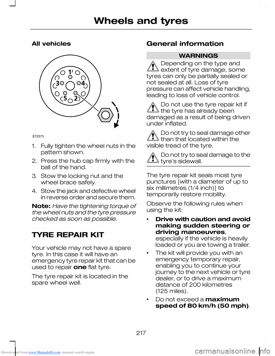
1.Fully tighten the wheel nuts in thepattern shown.
2.Press the hub cap firmly with theball of the hand.
3.Stow the locking nut and thewheel brace safely.
4.Stow the jack and defective wheelin reverse order and secure them.
Note:Have the tightening torque ofthe wheel nuts and the tyre pressurechecked as soon as possible.
TYRE REPAIR KIT
Your vehicle may not have a sparetyre. In this case it will have anemergency tyre repair kit that can beused to repair one flat tyre.
The tyre repair kit is located in thespare wheel well.
General information
WARNINGS
Depending on the type andextent of tyre damage, sometyres can only be partially sealed ornot sealed at all. Loss of tyrepressure can affect vehicle handling,leading to loss of vehicle control.
Do not use the tyre repair kit ifthe tyre has already beendamaged as a result of being drivenunder inflated.
Do not try to seal damage otherthan that located within thevisible tread of the tyre.
Do not try to seal damage to thetyre’s sidewall.
The tyre repair kit seals most tyrepunctures [with a diameter of up tosix millimetres (1/4 inch)] totemporarily restore mobility.
Observe the following rules whenusing the kit:
•Drive with caution and avoidmaking sudden steering ordriving manoeuvres,especially if the vehicle is heavilyloaded or you are towing a trailer.
•The kit will provide you with anemergency temporary repair,enabling you to continue yourjourney to the next vehicle or tyredealer, or to drive a maximumdistance of 200 kilometres(125 miles).
•Do not exceed a maximumspeed of 80 km/h (50 mph).
217
Wheels and tyresE72573