Abs FORD C MAX 2008 1.G Owners Manual
[x] Cancel search | Manufacturer: FORD, Model Year: 2008, Model line: C MAX, Model: FORD C MAX 2008 1.GPages: 278, PDF Size: 17.5 MB
Page 5 of 278
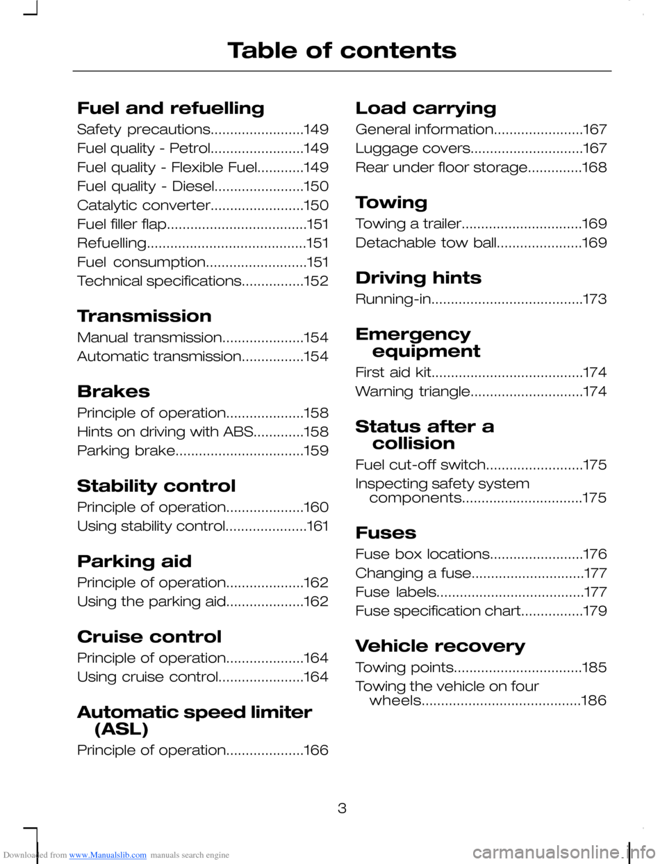
Downloaded from www.Manualslib.com manuals search engine Fuel and refuelling
Safety precautions........................149
Fuel quality - Petrol........................149
Fuel quality - Flexible Fuel............149
Fuel quality - Diesel.......................150
Catalytic converter........................150
Fuel filler flap....................................151
Refuelling.........................................151
Fuel consumption..........................151
Technical specifications................152
Transmission
Manual transmission.....................154
Automatic transmission................154
Brakes
Principle of operation....................158
Hints on driving with ABS.............158
Parking brake.................................159
Stability control
Principle of operation....................160
Using stability control.....................161
Parking aid
Principle of operation....................162
Using the parking aid....................162
Cruise control
Principle of operation....................164
Using cruise control......................164
Automatic speed limiter
(ASL)
Principle of operation....................166
Load carrying
General information.......................167
Luggage covers.............................167
Rear under floor storage..............168
Towing
Towing a trailer...............................169
Detachable tow ball......................169
Driving hints
Running-in.......................................173
Emergency
equipment
First aid kit.......................................174
Warning triangle.............................174
Status after a
collision
Fuel cut-off switch.........................175
Inspecting safety systemcomponents...............................175
Fuses
Fuse box locations........................176
Changing a fuse.............................177
Fuse labels......................................177
Fuse specification chart................179
Vehicle recovery
Towing points.................................185
Towing the vehicle on fourwheels.........................................186
3
Table of contents
Page 77 of 278
Downloaded from www.Manualslib.com manuals search engine Disconnect the wiring connector.
Install in the reverse order.
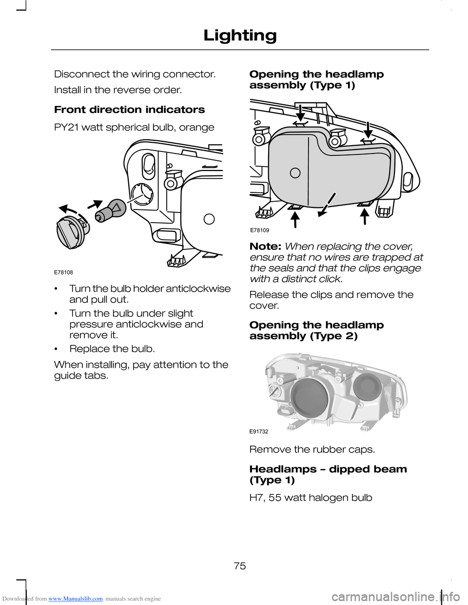
Front direction indicators
PY21 watt spherical bulb, orange
•Turn the bulb holder anticlockwiseand pull out.
•Turn the bulb under slightpressure anticlockwise andremove it.
•Replace the bulb.
When installing, pay attention to theguide tabs.
Opening the headlampassembly (Type 1)
Note:When replacing the cover,ensure that no wires are trapped atthe seals and that the clips engagewith a distinct click.
Release the clips and remove thecover.
Opening the headlampassembly (Type 2)
Remove the rubber caps.
Headlamps – dipped beam(Type 1)
H7, 55 watt halogen bulb
75
LightingE78108 E78109 E91732
Page 79 of 278
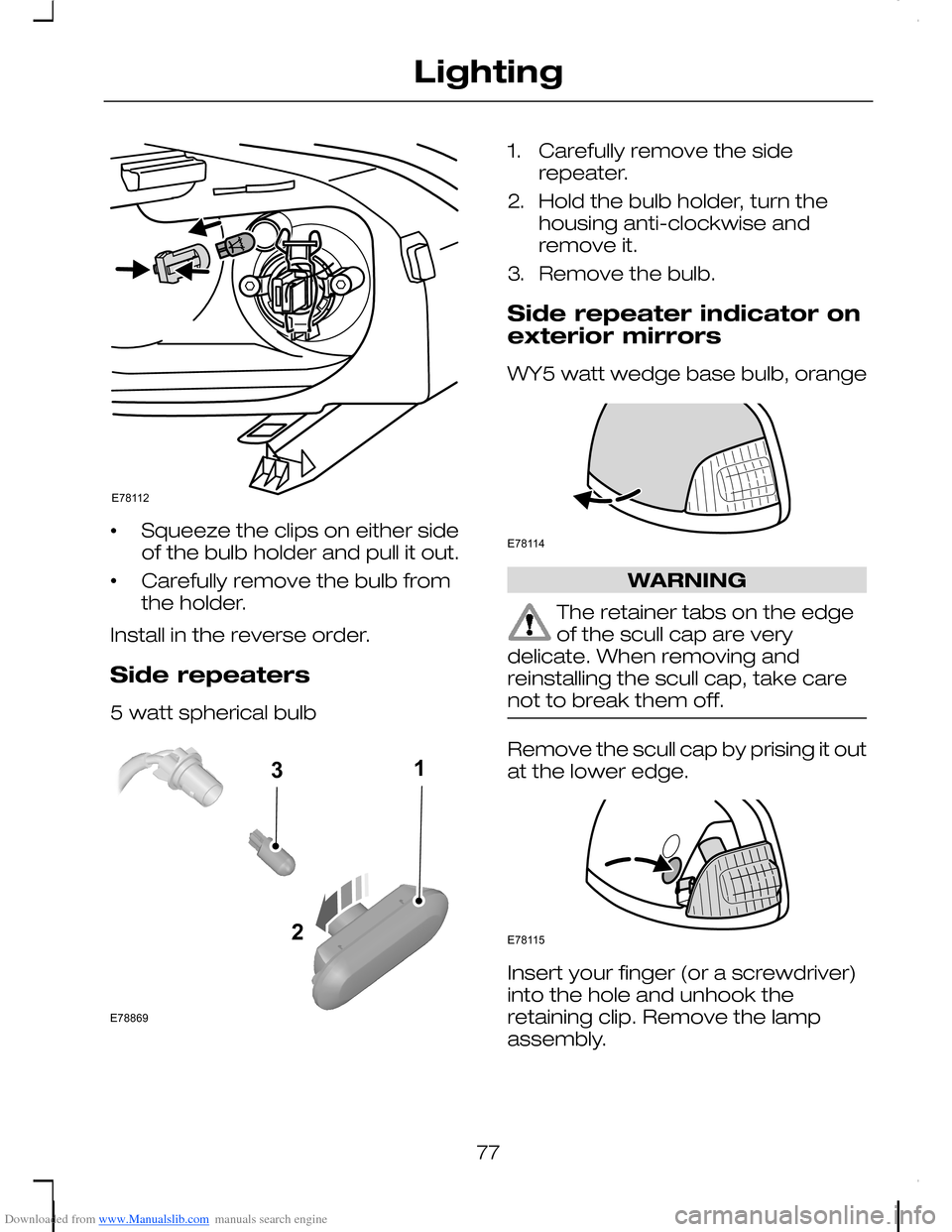
Downloaded from www.Manualslib.com manuals search engine •Squeeze the clips on either sideof the bulb holder and pull it out.
•Carefully remove the bulb fromthe holder.
Install in the reverse order.
Side repeaters
5 watt spherical bulb
1.Carefully remove the siderepeater.
2.Hold the bulb holder, turn thehousing anti-clockwise andremove it.
3.Remove the bulb.
Side repeater indicator onexterior mirrors
WY5 watt wedge base bulb, orange
WARNING
The retainer tabs on the edgeof the scull cap are verydelicate. When removing andreinstalling the scull cap, take carenot to break them off.
Remove the scull cap by prising it outat the lower edge.
Insert your finger (or a screwdriver)into the hole and unhook theretaining clip. Remove the lampassembly.
77
LightingE78112 213E78869 E78114 E78115
Page 92 of 278
Downloaded from www.Manualslib.com manuals search engine Engine coolant temperaturegauge
All vehicles
Shows the temperature of the enginecoolant. At normal operatingtemperature, the needle will remainin the centre section.
CAUTION
Do not restart the engine until thecause of overheating has beenresolved.
If the needle enters the red section,the engine is overheating. Stop theengine, switch the ignition off anddetermine the cause once theengine has cooled down. SeeEngine coolant check (page 201).
Fuel gauge
The arrow adjacent to the fuel pumpsymbol indicates on which side of thevehicle the fuel filler cap is located.
WARNING LAMPS AND
INDICATORS
The following warning lamps andindicators illuminate when the ignitionis switched on:
•Airbag
•Oil pressure
•Engine immobiliser
•ABS
•Stability control (ESP)
•Engine
•Doors open
•Brake system
•Engine systems fault
•Frost
•Power steering
•Ignition
If a warning lamp or indicator doesnot illuminate when the ignition isswitched on, it indicates amalfunction. Have the systemchecked by an expert.
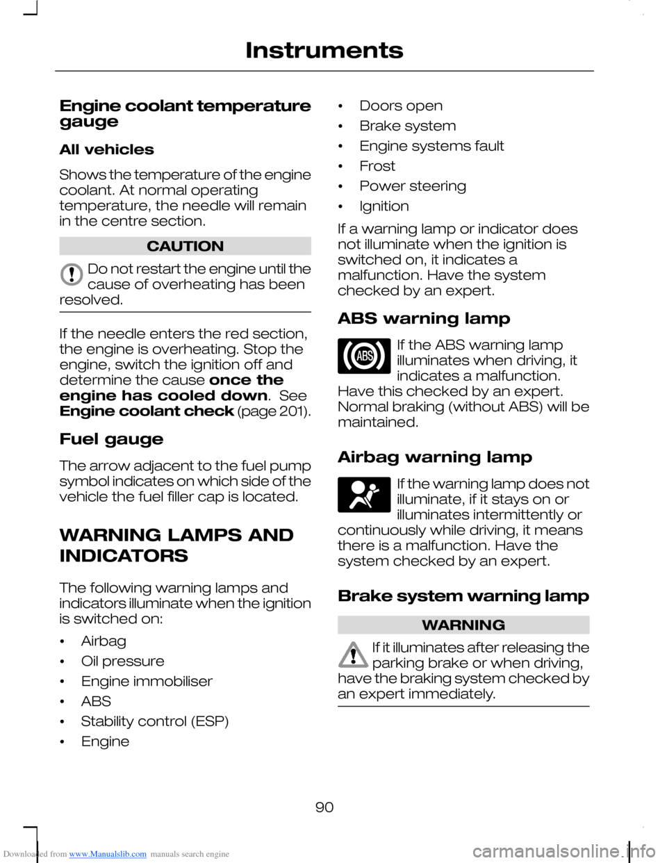
ABS warning lamp
If the ABS warning lampilluminates when driving, itindicates a malfunction.Have this checked by an expert.Normal braking (without ABS) will bemaintained.
Airbag warning lamp
If the warning lamp does notilluminate, if it stays on orilluminates intermittently orcontinuously while driving, it meansthere is a malfunction. Have thesystem checked by an expert.
Brake system warning lamp
WARNING
If it illuminates after releasing theparking brake or when driving,have the braking system checked byan expert immediately.
90
Instruments
Page 93 of 278
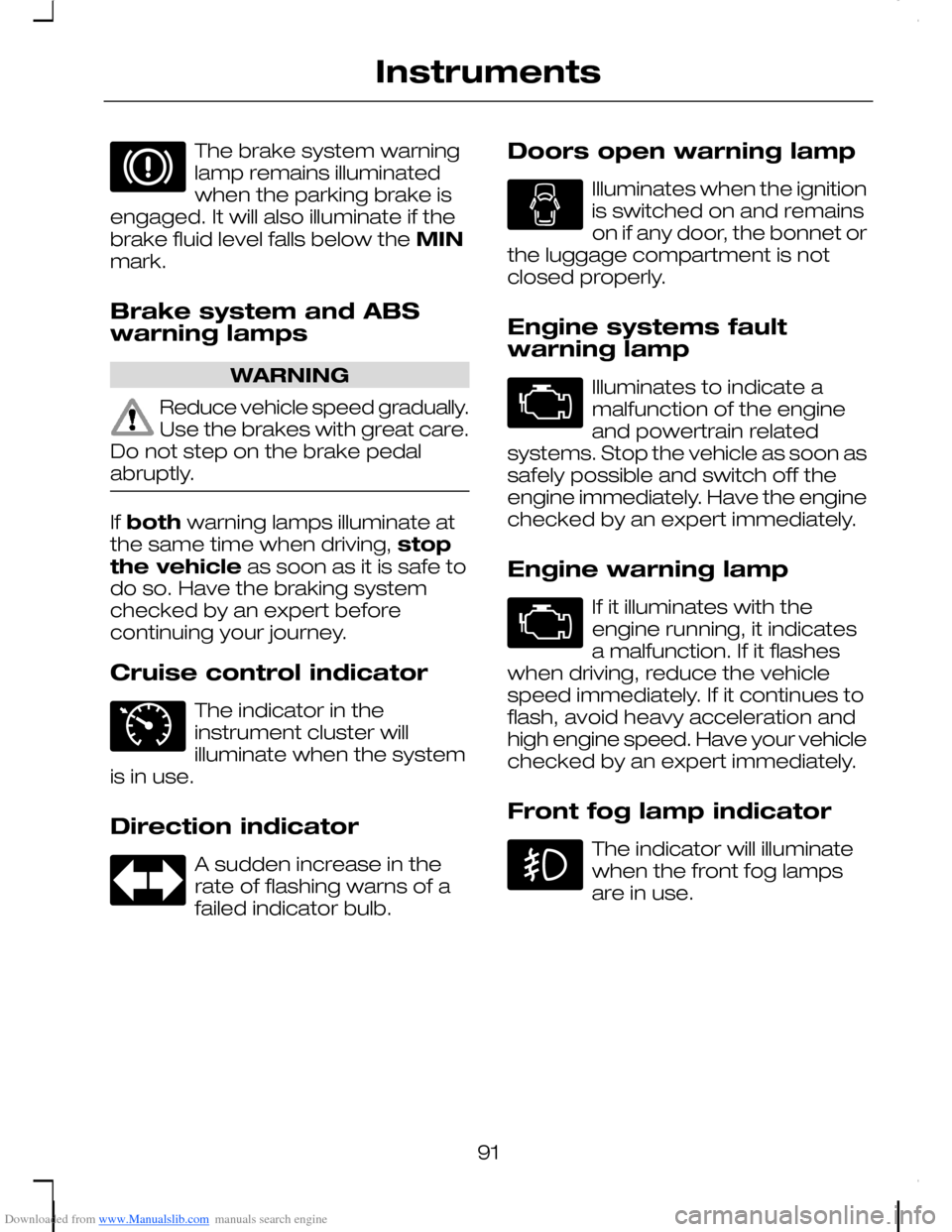
Downloaded from www.Manualslib.com manuals search engine The brake system warninglamp remains illuminatedwhen the parking brake isengaged. It will also illuminate if thebrake fluid level falls below the MINmark.
Brake system and ABSwarning lamps
WARNING
Reduce vehicle speed gradually.Use the brakes with great care.Do not step on the brake pedalabruptly.
If both warning lamps illuminate atthe same time when driving, stopthe vehicle as soon as it is safe todo so. Have the braking systemchecked by an expert beforecontinuing your journey.
Cruise control indicator
The indicator in theinstrument cluster willilluminate when the systemis in use.
Direction indicator
A sudden increase in therate of flashing warns of afailed indicator bulb.
Doors open warning lamp
Illuminates when the ignitionis switched on and remainson if any door, the bonnet orthe luggage compartment is notclosed properly.
Engine systems faultwarning lamp
Illuminates to indicate amalfunction of the engineand powertrain relatedsystems. Stop the vehicle as soon assafely possible and switch off theengine immediately. Have the enginechecked by an expert immediately.
Engine warning lamp
If it illuminates with theengine running, it indicatesa malfunction. If it flasheswhen driving, reduce the vehiclespeed immediately. If it continues toflash, avoid heavy acceleration andhigh engine speed. Have your vehiclechecked by an expert immediately.
Front fog lamp indicator
The indicator will illuminatewhen the front fog lampsare in use.
91
Instruments E71340
Page 144 of 278
Downloaded from www.Manualslib.com manuals search engine Position I
Steering unlocked. Ignition and allmain electrical circuits are disabled.The ignition key should not be left inthis position for too long to avoiddischarging the battery.
Positon II
Ignition switched on, all electricalcircuits operational. Warning andindicator lamps illuminate. This is thekey position when driving, and mustalso be selected when being towed.
Postion III
Starter motor activated. Release thekey as soon as the engine starts.
STEERING WHEEL LOCK
WARNING
Always check that the steeringis unlocked before attemptingto move your vehicle.
Vehicles without keylessstarting
To activate the steering wheel lock;
1.Remove the key from the ignitionswitch.
2.Turn the steering wheel.
Vehicles with keylessstarting
Your vehicle has an electronicallycontrolled steering wheel lock. Thisoperates automatically.
The steering wheel lock is activatedif the ignition is off, the engine notrunning and your vehicle is stationary.
The steering wheel lock isdeactivated when the ignition isswitched on.
STARTING A PETROL
ENGINE
All vehicles
WARNING
If the engine does not start,refer to the instructionsregarding the fuel cut-off switch. SeeFuel cut-off switch (page 175).
Engine idle speed afterstarting
The speed at which the engine idlesimmediately after starting will varydepending on the enginetemperature.
If the engine is cold then the idlespeed will automatically be increasedin order to heat the catalyticconverter as quickly as possible. Thisensures that vehicle emissions arekept to an absolute minimum.
The idle speed will slowly decreaseto the normal level as the catalyticconverter warms up.
142
Starting the engine
Page 160 of 278
Downloaded from www.Manualslib.com manuals search engine PRINCIPLE OF
OPERATION
Dual circuit braking system
WARNING
If a brake circuit fails, you willnotice a softer feel to the brakepedal. Press the brake pedal firmlyand allow for increased stoppingdistances. Stop and have thischecked immediately. Do notcontinue your journey.
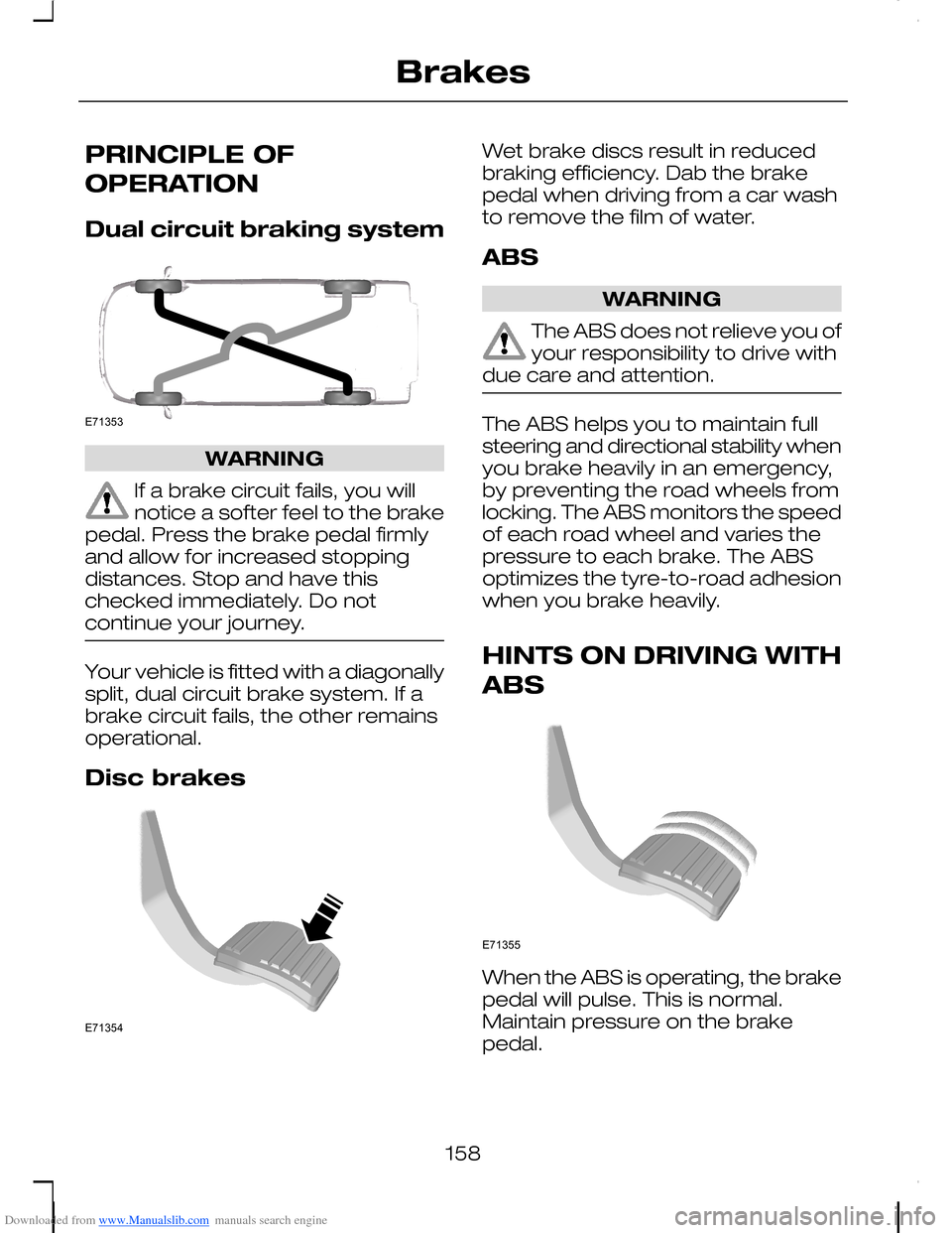
Your vehicle is fitted with a diagonallysplit, dual circuit brake system. If abrake circuit fails, the other remainsoperational.
Disc brakes
Wet brake discs result in reducedbraking efficiency. Dab the brakepedal when driving from a car washto remove the film of water.
ABS
WARNING
The ABS does not relieve you ofyour responsibility to drive withdue care and attention.
The ABS helps you to maintain fullsteering and directional stability whenyou brake heavily in an emergency,by preventing the road wheels fromlocking. The ABS monitors the speedof each road wheel and varies thepressure to each brake. The ABSoptimizes the tyre-to-road adhesionwhen you brake heavily.
HINTS ON DRIVING WITH
ABS
When the ABS is operating, the brakepedal will pulse. This is normal.Maintain pressure on the brakepedal.
158
BrakesE71353 E71354 E71355
Page 161 of 278
Downloaded from www.Manualslib.com manuals search engine The ABS will not eliminate thedangers inherent when:
•you drive too close to the vehiclein front of you.
•the vehicle is aquaplaning.
•you take corners too fast.
•the road surface is poor.
PARKING BRAKE
All vehicles
WARNING
Vehicles with an automatictransmission should always beleft with the selector lever in positionP.
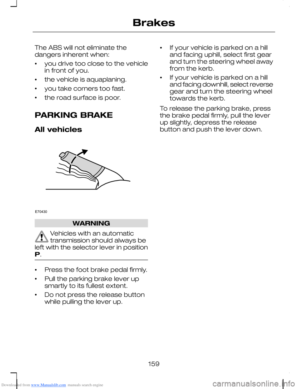
•Press the foot brake pedal firmly.
•Pull the parking brake lever upsmartly to its fullest extent.
•Do not press the release buttonwhile pulling the lever up.
•If your vehicle is parked on a hilland facing uphill, select first gearand turn the steering wheel awayfrom the kerb.
•If your vehicle is parked on a hilland facing downhill, select reversegear and turn the steering wheeltowards the kerb.
To release the parking brake, pressthe brake pedal firmly, pull the leverup slightly, depress the releasebutton and push the lever down.
159
BrakesE70430
Page 164 of 278
Downloaded from www.Manualslib.com manuals search engine PRINCIPLE OF
OPERATION
WARNING
The parking aid does not relieveyou of your responsibility todrive with due care and attention.
CAUTIONS
The sensors may not detectobjects in heavy rain or otherconditions that cause disruptivereflections.
The sensors may not detectobjects with surfaces that absorbultrasonic waves.
The sensors may not detectobjects that are close to thevehicle (approximately 30centimetres [11 inches] to the rearand above or below the sensors).
If you use a high pressure sprayto wash your vehicle, only spraythe sensors briefly from a distancenot less than 20 centimetres (8inches).
Note:The parking aid may emit falsetones if it detects a signal using thesame frequency as the sensors or ifthe vehicle is fully laden.
Note:The outer sensors may detectthe side walls of a garage. If thedistance between the outer sensorand the side wall remains constantfor three seconds, the tone willswitch off. As you continue, the innersensors will detect rearward objects.
USING THE PARKING AID
Note:Keep the sensors free fromdirt, ice and snow. Do not clean withsharp objects.
Switching the parking aidon and off
Note:The parking aid switches offautomatically when you start theengine or when you exceed 16 km/h(10 mph).
Note:Vehicles fitted with a trailertow module not approved by us maynot correctly detect obstacles.
Note:On vehicles fitted with a towball arm, the rear sensors aredeactivated automatically when anytrailer lamps (or lighting boards) areconnected to the 13-pin socket via atrailer tow module we haveapproved. On vehicles fitted with atrailer tow module not approved byus, you have to switch the parkingaid off using the switch.
Note:The front and rear sensors arealways activated or deactivatedtogether.
Note:On vehicles fitted withautomatic transmission, the parkingaid will not operate in position P.
The parking aid is per default off. Toswitch the parking aid on, press theswitch in the instrument panel orselect reverse gear.
The light in the switch illuminateswhen the parking aid is activated.
To turn it off, press the switch again.
162
Parking aid
Page 171 of 278
Downloaded from www.Manualslib.com manuals search engine TOWING A TRAILER
WARNINGS
Do not exceed the maximumvehicle and trailer weight statedon the vehicle identification plate. SeeVehicle identification (page 226).
ST vehicles are not approvedfor trailer towing.
Note:Not all vehicles are suitable orapproved to have tow bars fitted.Check with your dealer first.
Place loads as low and central to theaxle(s) of the trailer as possible. If youare towing with an unladen vehicle,the load in the trailer should beplaced toward the nose, within themaximum nose load, as this gives thebest stability.
Note:The maximum trailer noseweight can be found on themanufacturers data plate on the towbar.
The stability of the vehicle to trailercombination is very much dependanton the quality of the trailer.
In high altitude regions, the stipulatedmaximum permitted gross trainweight must be reduced by 10% forevery 1 000 metres (3 281 feet).
Steep gradients
WARNING
The overrun brake on a trailer isnot controlled by ABS.
Change down a gear before youreach a steep downhill gradient.
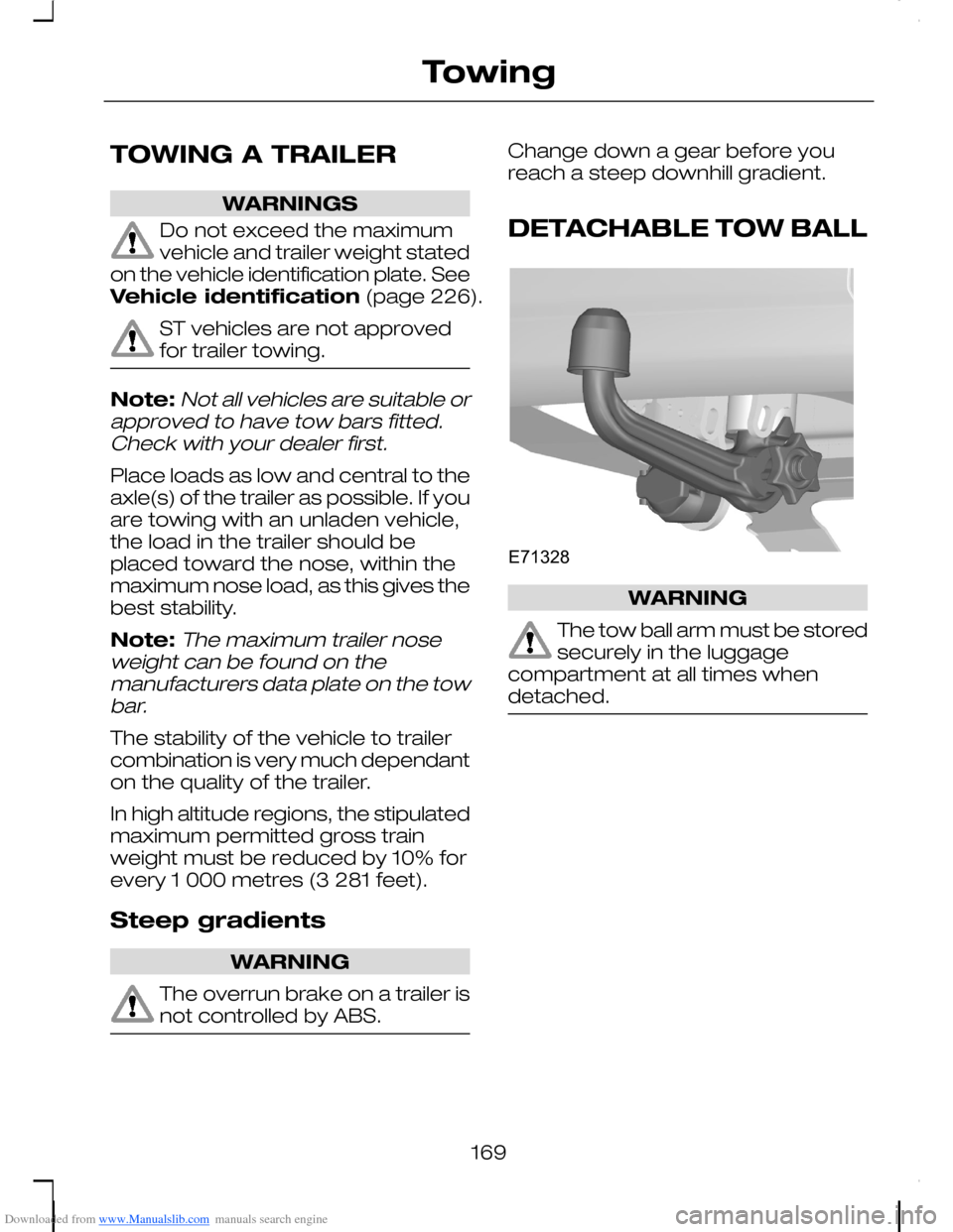
DETACHABLE TOW BALL
WARNING
The tow ball arm must be storedsecurely in the luggagecompartment at all times whendetached.
169
TowingE71328