instrument panel FORD C MAX 2011 2.G Owners Manual
[x] Cancel search | Manufacturer: FORD, Model Year: 2011, Model line: C MAX, Model: FORD C MAX 2011 2.GPages: 296, PDF Size: 7.87 MB
Page 12 of 296
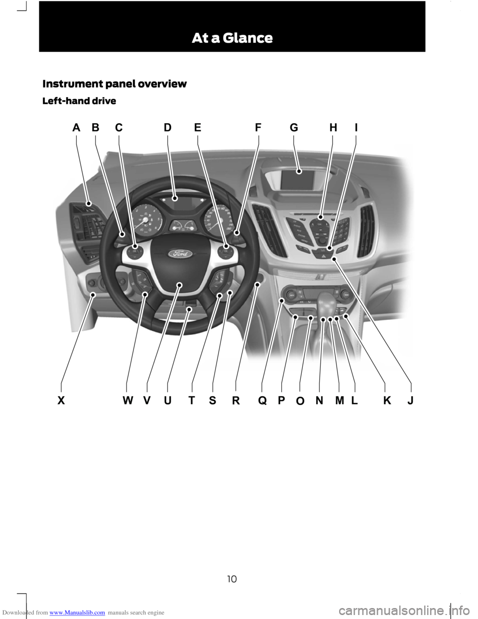
Downloaded from www.Manualslib.com manuals search engine Instrument panel overview
Left-hand drive
10At a GlanceE130098HIGFEDCBAXWVUTSQPORLMNJK
Page 36 of 296
Downloaded from www.Manualslib.com manuals search engine WARNING
Position the seat belt correctly for
your safety and that of your unborn
child. Do not use only the lap strap
or the shoulder strap. Position the lap strap comfortably across
your hips and low beneath your pregnant
abdomen. Position the shoulder strap
between your breasts, above and to the
side of your pregnant abdomen.
DISABLING THE PASSENGER
AIRBAG
WARNING
Make sure that the passenger airbag
is disabled when using a rearward
facing child restraint on the front
passenger seat. Fitting the passenger airbag
deactivation switch
WARNING
If you need to fit a child restraint on
a seat protected by an operational
airbag in front of it, have a passenger
airbag deactivation switch fitted. Ask your
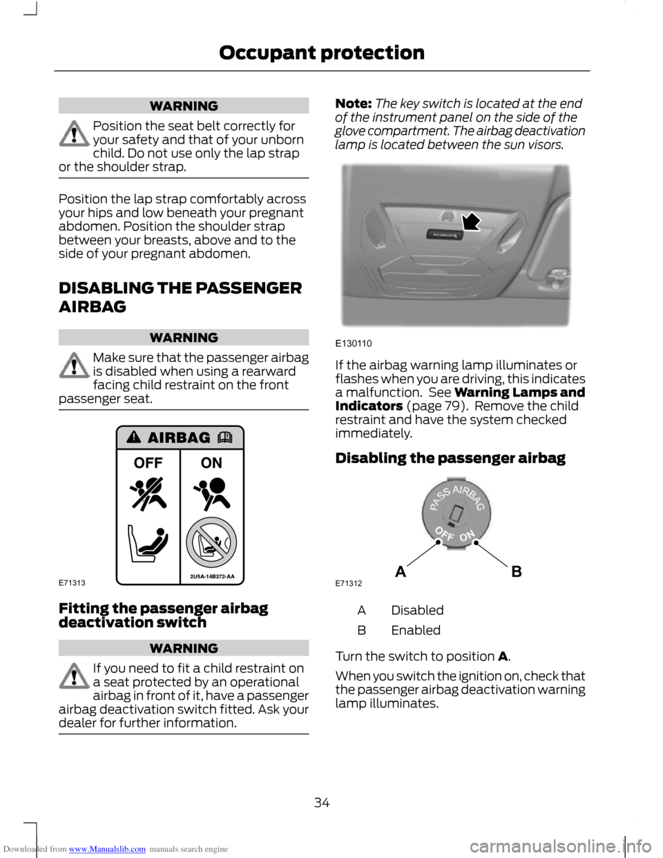
dealer for further information. Note:
The key switch is located at the end
of the instrument panel on the side of the
glove compartment. The airbag deactivation
lamp is located between the sun visors. If the airbag warning lamp illuminates or
flashes when you are driving, this indicates
a malfunction. See Warning Lamps and
Indicators (page 79). Remove the child
restraint and have the system checked
immediately.
Disabling the passenger airbag
Disabled
A
Enabled
B
Turn the switch to position A.
When you switch the ignition on, check that
the passenger airbag deactivation warning
lamp illuminates.
34
Occupant protectionE71313 E130110 ABE71312
Page 47 of 296
Downloaded from www.Manualslib.com manuals search engine Unlocking only the driver's door
If the unlocking function is reprogrammed
so that only the driver
’s door and the
luggage compartment lid are unlocked (
See Programming the remote control
(page 36). ), note the following:
If the driver ’s door is the first door which is
opened, the other doors will remain locked.
All the other doors can be unlocked from
inside the vehicle by pressing the unlock
button on the instrument panel. For item
location: See At a Glance (page 10).
Doors can be unlocked individually by
pulling the interior door handles on those
doors.
Disabled keys
Any keys left inside the vehicle interior
when it is locked will be disabled.
A disabled key cannot be used to turn the
ignition on or start the engine.
In order to use these passive keys again,
they have to be enabled.
To enable all your passive keys, unlock the
vehicle using a passive key or the remote
control unlocking function.
All passive keys will then be enabled if the
ignition is turned on or the vehicle is started
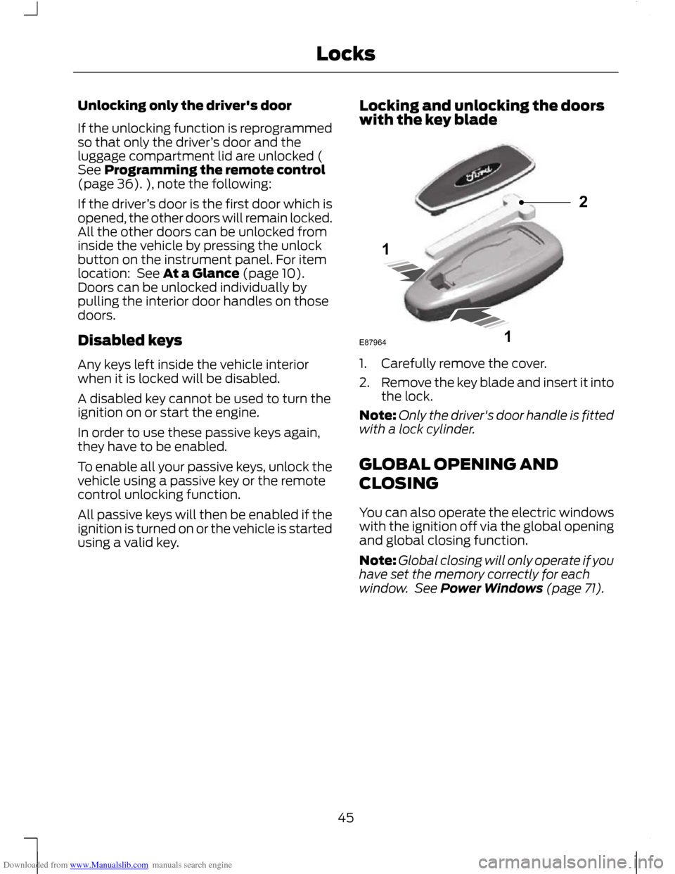
using a valid key. Locking and unlocking the doors
with the key blade 1. Carefully remove the cover.
2.
Remove the key blade and insert it into
the lock.
Note: Only the driver's door handle is fitted
with a lock cylinder.
GLOBAL OPENING AND
CLOSING
You can also operate the electric windows
with the ignition off via the global opening
and global closing function.
Note: Global closing will only operate if you
have set the memory correctly for each
window. See Power Windows (page 71).
45
Locks121E87964
Page 105 of 296
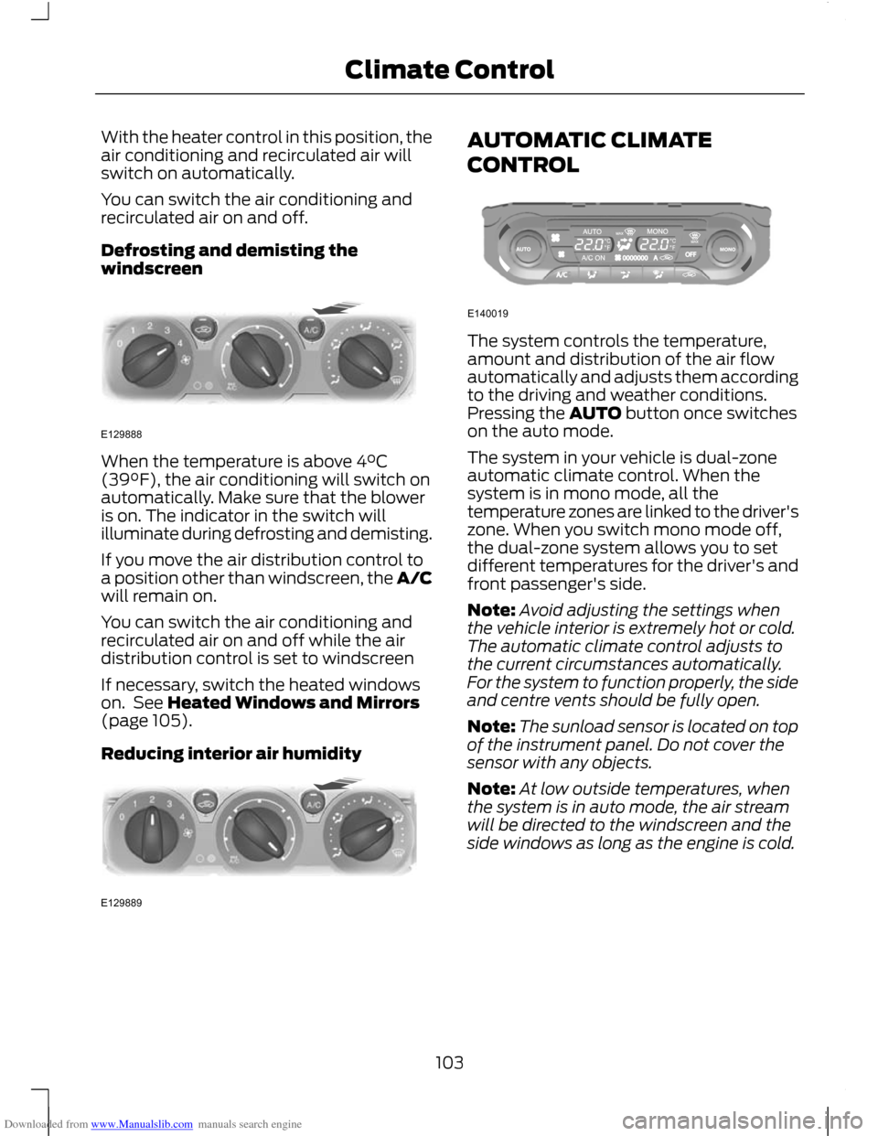
Downloaded from www.Manualslib.com manuals search engine With the heater control in this position, the
air conditioning and recirculated air will
switch on automatically.
You can switch the air conditioning and
recirculated air on and off.
Defrosting and demisting the
windscreen
When the temperature is above 4°C
(39°F), the air conditioning will switch on
automatically. Make sure that the blower
is on. The indicator in the switch will
illuminate during defrosting and demisting.
If you move the air distribution control to
a position other than windscreen, the A/C
will remain on.
You can switch the air conditioning and
recirculated air on and off while the air
distribution control is set to windscreen
If necessary, switch the heated windows
on. See Heated Windows and Mirrors
(page 105).
Reducing interior air humidity AUTOMATIC CLIMATE
CONTROL
The system controls the temperature,
amount and distribution of the air flow
automatically and adjusts them according
to the driving and weather conditions.
Pressing the AUTO button once switches
on the auto mode.
The system in your vehicle is dual-zone
automatic climate control. When the
system is in mono mode, all the
temperature zones are linked to the driver's
zone. When you switch mono mode off,
the dual-zone system allows you to set
different temperatures for the driver's and
front passenger's side.
Note:
Avoid adjusting the settings when
the vehicle interior is extremely hot or cold.
The automatic climate control adjusts to
the current circumstances automatically.
For the system to function properly, the side
and centre vents should be fully open.
Note: The sunload sensor is located on top
of the instrument panel. Do not cover the
sensor with any objects.
Note: At low outside temperatures, when
the system is in auto mode, the air stream
will be directed to the windscreen and the
side windows as long as the engine is cold.
103
Climate ControlE129888 E129889 E140019
Page 135 of 296
Downloaded from www.Manualslib.com manuals search engine PRINCIPLE OF OPERATION
CAUTION
For vehicles with Start-stop the
battery requirement is different. It
must be replaced by one of exactly
the same specification as the original. The system reduces fuel consumption and
CO2 emissions by shutting down the
engine when the vehicle is idling, for
example at traffic lights. The engine will
automatically restart when the driver
presses the clutch pedal or when required
by a vehicle system, for example to
recharge the battery.
To obtain maximum benefit from the
system, move the gear lever to the neutral
position and release the clutch pedal
during any stop of longer than three
seconds.
USING START-STOP
WARNINGS
The engine may restart
automatically if required by the
system. See Principle of Operation
(page 133). Switch the ignition off before
opening the bonnet or carrying out
any maintenance.
Always switch the ignition off before
leaving your vehicle, as the system
may have shut down the engine but
the ignition will still be live. Note:
The system only operates when the
engine is warm and the outside temperature
is between 0°C (32°F) and 30°C (86°F). Note:
If you stall the engine, and then
depress the clutch pedal within a couple of
seconds, the system will automatically
restart the engine.
Note: The Start-stop indicator will
illuminate green when the engine shuts
down. See Warning Lamps and Indicators
(page 79).
Note: The Start-stop indicator will flash
amber, requiring you to select neutral or
depress the clutch pedal. In conjunction a
message will be shown in the display.
Note: If the system detects a malfunction,
it is deactivated. Have the system checked
by a properly trained technician.
Note: If you have switched the system off,
the switch will be illuminated.
Note: The system is on by default. To
switch the system off, press the switch in
the instrument panel. The system will only
be de-activated for the current ignition
cycle. To turn it on, press the switch again.
For item location. See At a Glance (page
10). To stop the engine
1. Stop the vehicle.
2. Move the gear lever to the neutral
position.
3. Release the clutch pedal.
4. Release the accelerator pedal.
The system may not shut down the engine
under certain conditions, for example:
• To maintain the interior climate.
• Low battery voltage.
• The outside temperature is too low or
too high.
• The driver's door has been opened.
133
Start-Stop
Page 144 of 296
Downloaded from www.Manualslib.com manuals search engine Neutral
In this position, power is not transmitted
to the drive wheels but the transmission is
not locked. You can start the engine with
the selector lever in this position.
Drive
Select drive to shift automatically through
the forward gears.
The transmission will select the
appropriate gear for optimum performance
based on ambient temperature, road
gradient, vehicle load and driver input.
Manual shifting - Vehicles with a
5 speed transmission
WARNING
Do not hold the selector lever
permanently in – or +.
CAUTION
The transmission will automatically
downshift when the engine speed is
too low and upshift when too high.
Note:
A shift will occur only when the
vehicle speed and the engine speed are
appropriate.
Note: In Select mode the current gear (1,
2, 3, 4 or 5) will be displayed on the
instrument panel.
Move the selector lever to position S.
Push the selector lever forwards to shift
down and pull it backwards to shift up.
Gears may be skipped by moving the
selector lever repeatedly at short intervals.
Manual mode also provides a kickdown
function. See Kickdown. Sport mode and manual shifting -
Vehicles with a 6 speed
transmission
Note:
A shift will occur only when the
vehicle speed and the engine speed are
appropriate.
Sport Mode
Note: In Sport mode the transmission
operates as normal but gears are selected
more quickly and at higher engine speeds.
Note: In Sport mode S will be displayed on
the instrument panel.
Activate Sport mode by moving the
selector lever to position S. Sport mode
will remain active until either you shift
manually up or down the gears or return
the selector lever to position D.
Manual shifting WARNING
Do not hold the selector lever
permanently in – or +.
CAUTION
The transmission will automatically
downshift when the engine speed is
too low.
Push the selector lever forwards to shift
down and pull it backwards to shift up.
Gears may be skipped by moving the
selector lever repeatedly at short intervals.
Manual mode also provides a kickdown
function. See Kickdown.
142
Transmission
Page 151 of 296
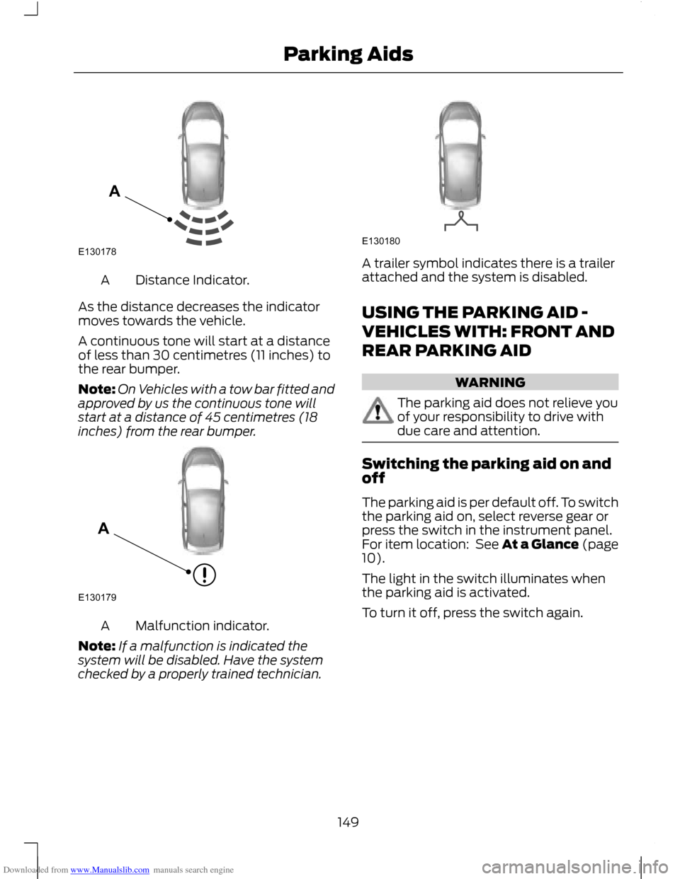
Downloaded from www.Manualslib.com manuals search engine Distance Indicator.
A
As the distance decreases the indicator
moves towards the vehicle.
A continuous tone will start at a distance
of less than 30 centimetres (11 inches) to
the rear bumper.
Note: On Vehicles with a tow bar fitted and
approved by us the continuous tone will
start at a distance of 45 centimetres (18
inches) from the rear bumper. Malfunction indicator.
A
Note: If a malfunction is indicated the
system will be disabled. Have the system
checked by a properly trained technician. A trailer symbol indicates there is a trailer
attached and the system is disabled.
USING THE PARKING AID -
VEHICLES WITH: FRONT AND
REAR PARKING AID
WARNING
The parking aid does not relieve you
of your responsibility to drive with
due care and attention.
Switching the parking aid on and
off
The parking aid is per default off. To switch
the parking aid on, select reverse gear or
press the switch in the instrument panel.
For item location: See At a Glance (page
10).
The light in the switch illuminates when
the parking aid is activated.
To turn it off, press the switch again.
149
Parking AidsE130178A E130179A E130180
Page 157 of 296
Downloaded from www.Manualslib.com manuals search engine PRINCIPLE OF OPERATION
The camera is a visual aid for use when
reversing.
WARNING
The system does not relieve you of
your responsibility to drive with due
care and attention.
CAUTIONS
If you use a high pressure spray to
wash your vehicle, only spray the
camera briefly from a distance not
less than 20 centimetres (8 inches). Do not apply pressure to the camera.
Note:
Keep the camera free from dirt, ice
and snow. Do not clean with sharp objects,
degreaser, wax or organic products. Use only
a soft cloth.
During operation, guide lines appear in the
display which represent your vehicle's path
and approximate distance from rearward
objects.
USING THE REAR VIEW
CAMERA WARNINGS
The operation of the camera may
vary depending on the ambient
temperature, vehicle and road
conditions. The distances shown in the display
may differ from the actual distance.
Do not place objects in front of the
camera.
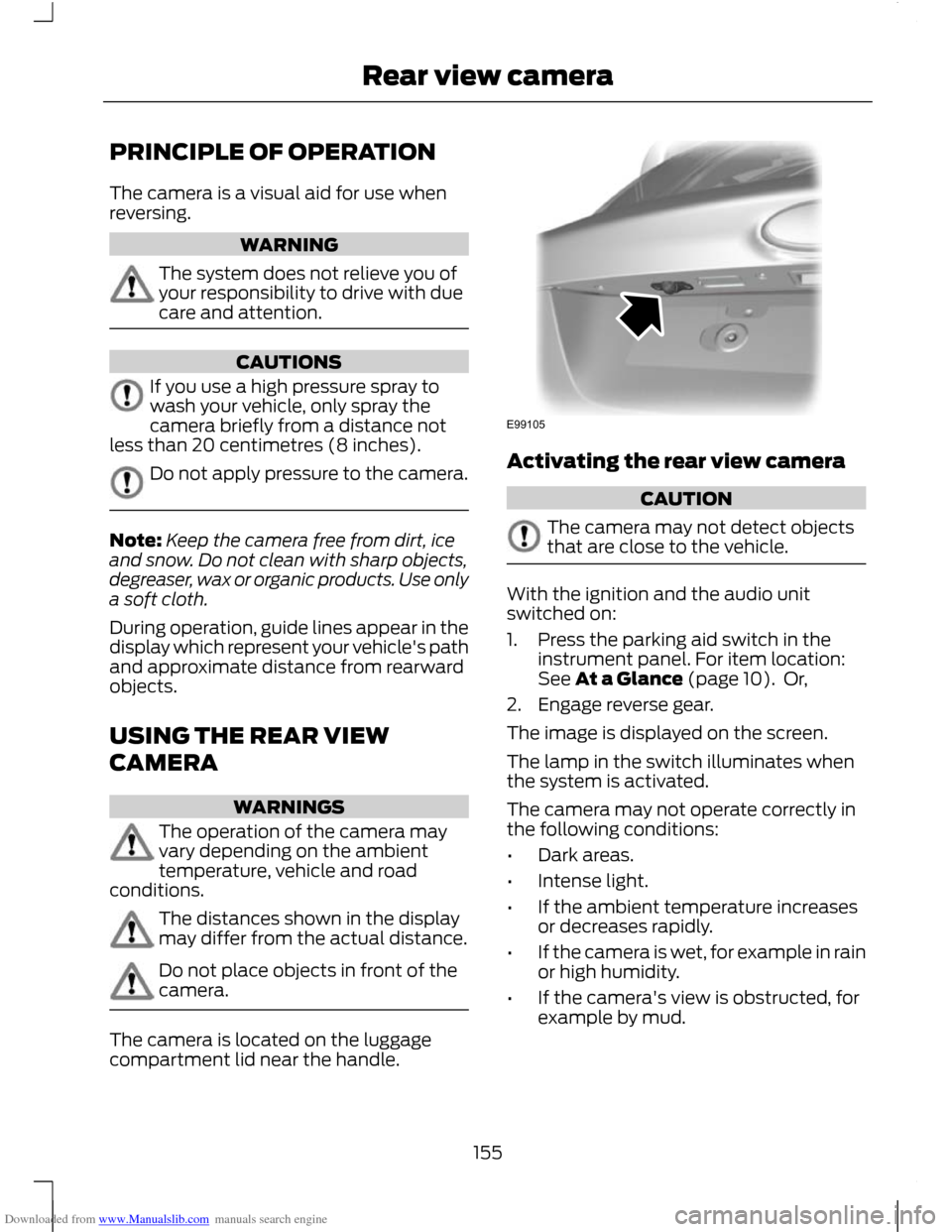
The camera is located on the luggage
compartment lid near the handle. Activating the rear view camera
CAUTION
The camera may not detect objects
that are close to the vehicle.
With the ignition and the audio unit
switched on:
1. Press the parking aid switch in the
instrument panel. For item location:
See At a Glance (page 10). Or,
2. Engage reverse gear.
The image is displayed on the screen.
The lamp in the switch illuminates when
the system is activated.
The camera may not operate correctly in
the following conditions:
• Dark areas.
• Intense light.
• If the ambient temperature increases
or decreases rapidly.
• If the camera is wet, for example in rain
or high humidity.
• If the camera's view is obstructed, for
example by mud.
155
Rear view cameraE99105
Page 159 of 296
Downloaded from www.Manualslib.com manuals search engine Green - 0.6 - 0.9 metre (24 - 35
inches)
D
Amber - centre line of the
projected vehicle path
E
Note: The green line is extended from 0.9
metre (35 inches) up to a distance of 3.2
metres (126 inches).
Note: When reversing with a trailer, the lines
on the screen are not shown. The camera
will show the vehicle direction and not the
trailer.
Deactivating the rear view camera
Note: Disengage reverse gear. The display
will stay on for a short period before
switching off.
Note: The system will automatically switch
off once the vehicle speed has reached
approximately 15 km/h (9 mph).
Press the parking aid switch in the
instrument panel. For item location: See
At a Glance (page 10).
Vehicles with parking aid
The display will additionally show a
coloured distance bar. This guide indicates
the distance from the rear bumper to the
detected obstacle.
These are colour coded as follows:
• Green - 0.6 to 1.8 metres (24 - 71
inches).
• Amber - 0.3 to 0.6 metre (12 - 24
inches).
• Red - 0.3 metre (12 inches) or less.
157
Rear view camera
Page 208 of 296
Downloaded from www.Manualslib.com manuals search engine Power plug with cable
G
Compressor switch
H
Label
I
Bottle lid
J
Sealant bottle
K
1. Open the lid of the tyre repair kit.
2. Peel off the label I showing the maximum permissible speed of
80 km/h (50 mph) from the casing and
attach it to the instrument panel in the
driver ’s field of view. Make sure the
label does not obscure anything
important.
3. Take the hose C and the power plug with cable G out of the kit.
4. Unscrew the orange cap D and the bottle lid J.
5. Screw the sealant bottle K clockwise into the bottle holder E fully tight.
6. Remove the valve cap from the damaged tyre.
7. Detach the protective cap A from the hose C and screw the hose C firmly
onto the valve of the damaged tyre.
8. Make sure that the compressor switch
H is in position 0.
9. Insert the power plug G into the cigar lighter socket or auxiliary power socket.
See Cigar Lighter (page 122). See
Auxiliary Power Points (page 123).
10. Start the engine.
11. Move the compressor switch H to position 1.
12. Inflate the tyre for no longer than seven minutes to an inflation pressure
of minimum 1.8 bar (26 psi) and a
maximum of 3.5 bar (51 psi). Move
the compressor switch H to position
0 and check the current tyre pressure
with pressure gauge F. 13. Remove the power plug G from the
cigar lighter socket or auxiliary power
socket.
14. Quickly unscrew the hose C from the
tyre valve and replace the protective
cap A. Fasten the valve cap again.
15. Leave the sealant bottle K in the bottle holder E.
16. Make sure the kit, the bottle lid and the orange cap are stored safely, but
still easily accessible in the vehicle.
The kit will be required again when
you check the tyre pressure.
17. Immediately drive approximately three kilometres (two miles) so that
the sealant can seal the damaged
area.
Note: When pumping in the sealant through
the tyre valve, the pressure may rise up to
6 bar (87 psi) but will drop again after about
30 seconds. WARNING
If you experience heavy vibrations,
unsteady steering behaviour or
noises while driving, reduce your
speed and drive with caution to a place
where it is safe for you to stop the vehicle.
Recheck the tyre and its pressure. If the
tyre pressure is less than 1.3 bar (19 psi) or
if there are any cracks, bumps or similar
damage visible, do not continue driving
with this tyre. Checking the tyre pressure
1. Stop the vehicle after driving
approximately three kilometres
(two miles). Check, and where
necessary, adjust the pressure of the
damaged tyre.
2. Attach the kit and read the tyre pressure from the pressure gauge F.
206
Wheels and Tyres