lights FORD C MAX HYBRID 2013 2.G User Guide
[x] Cancel search | Manufacturer: FORD, Model Year: 2013, Model line: C MAX HYBRID, Model: FORD C MAX HYBRID 2013 2.GPages: 552, PDF Size: 8.55 MB
Page 236 of 552
Visual Park Aid Alert
Note:Visual park alert is only available when the transmission is in R
(Reverse).
Note:The reverse sensing system is not effective at speeds above 3 mph
(5 km/h) and may not detect certain angular or moving objects.
The visual park aid alert allows the driver to view the area that is being
detected by the reverse sensing system. The system uses red, yellow and
green highlights which appear on top of the video image when an object
is detected by the reverse sensing system. The alert highlights the
closest object detected. The reverse sensing alert can be disabled and if
visual park aid alert is enabled, highlighted areas are still displayed.
Selectable settings for this feature are ON and OFF.
Manual Zoom
WARNING:When manual zoom is on, the full area behind the
vehicle is not shown. Be aware of your surroundings when using
the manual zoom feature.
Note:Manual zoom is only available when the transmission is in R
(Reverse).
Note:When manual zoom is enabled, only the centerline is shown.
Allows the driver to get a closer view of an object behind the vehicle.
The zoomed image keeps the bumper in the image to provide a
reference. The zoom is only active while the transmission is in R
(Reverse), When the transmission is shifted out of R (Reverse), the
feature automatically turns off and must be reset when it is used again.
Selectable settings for this feature are OFF, Level 1, Level 2 or Level 3.
Press the up and down arrows to change the view. The selection level
appears between the buttons (i.e. Level 1). The default setting for the
manual zoom is OFF.
Rear Camera Delay
When shifting the transmission out of R (Reverse) and into any gear
other than P (Park), the camera image remains in the display until the
vehicle speed reaches 6 mph (10 km/h). This occurs when the rear
camera delay feature is on, or until a radio button is selected.
Selectable settings for this feature are ON and OFF. The default setting
for the rear camera delay is OFF.
Parking Aids235
2013 C-Max Full Hybrid(34h)
Owners Guide gf, 3rd Printing, January 2013
USA(fus)
Page 255 of 552
In the event of damage or fire involving an electric vehicle (EV) or
hybrid-electric vehicle (HEV):
•Always assume the high-voltage battery and associated components
are energized and fully charged.
•Exposed electrical components, wires, and high-voltage batteries
present potential high-voltage shock hazards.
•Venting/off-gassing high-voltage battery vapors are potentially toxic
and flammable.
•Physical damage to the vehicle or high-voltage battery may result in
immediate or delayed release of toxic and/or flammable gases and fire.
Vehicle information and general safety practices:
•Know the make and model of your vehicle.
•Review the Owner’s Manual and become familiar with your vehicle’s
safety information and recommended safety practices.
•Do not attempt to repair damaged electric and hybrid-electric vehicles
yourself. Contact an authorized Ford Dealer or vehicle manufacturer
representative for service.
Crashes
A crash or impact significant enough to require an emergency response
for conventional vehicles would also require the same response for an
electric or hybrid-electric vehicle.
If possible
•Move your car to a safe, nearby location and remain on the scene.
•Roll down windows before shutting vehicle off.
•Place vehicle in Park, set parking brake, turn off the vehicle, activate
hazard lights, and move key(s) at least 16 feet (5 meters) away from
the vehicle.
254Roadside Emergencies
2013 C-Max Full Hybrid(34h)
Owners Guide gf, 3rd Printing, January 2013
USA(fus)
Page 310 of 552
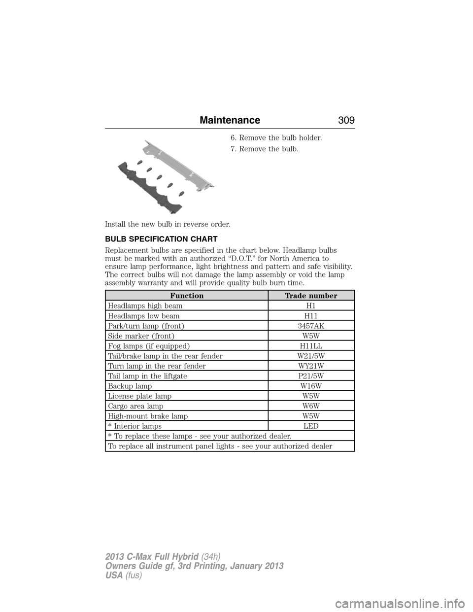
6. Remove the bulb holder.
7. Remove the bulb.
Install the new bulb in reverse order.
BULB SPECIFICATION CHART
Replacement bulbs are specified in the chart below. Headlamp bulbs
must be marked with an authorized “D.O.T.” for North America to
ensure lamp performance, light brightness and pattern and safe visibility.
The correct bulbs will not damage the lamp assembly or void the lamp
assembly warranty and will provide quality bulb burn time.
Function Trade number
Headlamps high beam H1
Headlamps low beam H11
Park/turn lamp (front) 3457AK
Side marker (front) W5W
Fog lamps (if equipped) H11LL
Tail/brake lamp in the rear fender W21/5W
Turn lamp in the rear fender WY21W
Tail lamp in the liftgate P21/5W
Backup lamp W16W
License plate lamp W5W
Cargo area lamp W6W
High-mount brake lamp W5W
* Interior lamps LED
* To replace these lamps - see your authorized dealer.
To replace all instrument panel lights - see your authorized dealer
Maintenance309
2013 C-Max Full Hybrid(34h)
Owners Guide gf, 3rd Printing, January 2013
USA(fus)
Page 343 of 552
Tips for Use of the Temporary Mobility Kit
Read the following list of tips to make sure safe operation of the
temporary mobility kit:
•Before operating the temporary mobility kit, make sure your vehicle is
safely off the road and away from moving traffic. Turn on the hazard
lights.
•Always set the parking brake to make sure the vehicle does not move
unexpectedly.
•
Do not remove any foreign objects, such as nails or screws, from the
tire.
•When using the temporary mobility kit, leave the engine running
(only if the vehicle is outdoors or in a well-ventilated area) so the
compressor does not drain the vehicle’s battery.
•Do not allow the compressor to operate continuously for more than
15 minutes; this will help prevent the compressor from overheating.
•Never leave the temporary mobility kit unattended when it is
operating.
•Sealant compound contains latex. Make sure that you use the
non-latex gloves provided to avoid an allergic reaction.
•Keep the temporary mobility kit away from children.
•Only use the temporary mobility kit when the ambient temperature is
between -22°F (–30°C) and 158°F (70°C).
•Only use the sealing compound before the use by date. The use by
date is on the lower right hand corner of the label located on the
sealant canister (bottle).Note:Check the use by date regularly and
replace the canister after four years.
•Do not store the temporary mobility kit unsecured inside the
passenger compartment of the vehicle as it may cause injury during a
sudden stop or collision. Always store the kit in its original location.
•
After sealant use, the tire pressure monitoring system sensor and valve
stem on the wheel must be replaced by an authorized Ford dealer.
•When inflating a tire or other objects, use the black air hose only. Do not
use the transparent hose which is designed for sealant application only.
•Operating the temporary mobility kit could cause an electrical
disturbance in radio, CD, and DVD player operation (if equipped).
342Wheels and Tires
2013 C-Max Full Hybrid(34h)
Owners Guide gf, 3rd Printing, January 2013
USA(fus)
Page 344 of 552
What to Do When a Tire Is Punctured
A tire puncture within the tire’s tread area can be repaired in two stages
with the temporary mobility kit:
•In the first stage, the tire will be reinflated with a sealing compound
and air. After the tire has been reinflated, you will need to drive the
vehicle a short distance (about 4 miles [6 kilometers]) to distribute
the sealant in the tire.
•In the second stage, check the tire pressure and adjust, if necessary,
to the vehicle’s tire inflation pressure.
First Stage: Reinflating the Tire with Sealing Compound and Air
WARNING:Do not stand directly over the temporary mobility
kit while inflating the tire. If you notice any unusual bulges or
deformations in the tire’s sidewall during inflation, stop and call
roadside assistance.
WARNING:If the tire does not inflate to the recommended tire
pressure within 15 minutes, stop and call roadside assistance.
Preparation
Park the vehicle in a safe, level and secure area, away from moving
traffic. Turn the hazard lights on. Apply the parking brake and turn the
engine off. Inspect the flat tire for visible damage.
Sealant compound contains latex. To avoid any allergic reactions, use the
non-latex gloves located in the accessory box on the underside of the
temporary mobility kit housing.
Do not remove any foreign object that has pierced the tire. If a puncture
is located in the tire sidewall, stop and call roadside assistance.
1. Remove the valve cap from the tire valve.
2. Unwrap the clear tube from the compressor housing.
3. Remove the tube cap and fasten the metal connector of the tube to
the tire valve, turning clockwise. Make sure the connection is tightly
fastened.
Wheels and Tires343
2013 C-Max Full Hybrid(34h)
Owners Guide gf, 3rd Printing, January 2013
USA(fus)
Page 366 of 552
Owner Checks and Services
Certain basic maintenance checks and inspections should be performed
every month or at six month intervals.
Check every month
Engine oil level.
Function of all interior and exterior lights.
Tires (including spare) for wear and proper pressure.
Windshield washer fluid level.
Check every six months
Battery connections. Clean if necessary.
Body and door drain holes for obstructions. Clean if necessary.
Cooling system fluid level and coolant strength.
Door weatherstrips for wear. Lubricate if necessary.
Hinges, latches and outside locks for proper operation. Lubricate if
necessary.
Parking brake for proper operation.
Safety belts and seat latches for wear and function.
Safety warning lamps (brake, ABS, airbag, safety belt) for operation.
Washer spray and wiper operation. Clean or replace blades as
necessary.
Scheduled Maintenance365
2013 C-Max Full Hybrid(34h)
Owners Guide gf, 3rd Printing, January 2013
USA(fus)
Page 477 of 552
The system also alerts you to any conflicts by highlighting areas of the
screen in yellow. If your battery cannot have a full charge by the
scheduled drive time, the system highlights the current My GO Time and
Actual Charge End Time and a messageCharge at GO Time: under
100%appears. This is normal; the vehicle is informing you of the
conflicting situation. This notification only displays when the gearshift
selector lever is in positionP.
Note:Charging occurs as soon as you plug the vehicle in. The system
limits cabin conditioning to 15 minutes before the My GO Time.
To eliminate the conflict notification immediately or to prevent a conflict
in the future, try the following:
•Change the present My GO Time to occur later.
•Plug the vehicle into a 240V charging station instead of 120V
convenience cord. Higher power charging yields shorter charge times.
•Plug the vehicle in sooner.
Estimated Charge Time Limits
Batteryshows you the battery’s current charge displayed as a
percentage. A reading of 100% means the battery has a full charge.
A reading of 0% means the battery has no charge.
To fully charge
•240Vis the estimated minimum charging time from the current
high-voltage battery level to full charge (100%). This represents the
shortest amount of time you should expect the high-voltage battery
to recharge under ideal conditions. Ideal conditions include a 240V
charging station and a minimum 30A service and high-voltage battery
at a moderate temperature.
Note:This charging time is only an estimate. It is normal for your actual
charge duration to be longer.
Note:Some charging stations use lower voltage (208V), which result in
longer charge times.
•120Vis the estimated maximum charging time from the current
high-voltage battery level to full charge (100%). This represents the
longest amount of time you should expect the high-voltage battery to
recharge under normal conditions. Normal conditions include a 120V
convenience cord and 12A service.
Note:This charging time is only an estimate. It is possible for your
actual charge duration to be longer. This occurs when the AC line
voltage is low and may indicate your electrical source is not meeting
certain requirements (seeCharging the high-voltage batteryin the
High Voltage Batterychapter).
476MyFord Touch® (If Equipped)
2013 C-Max Full Hybrid(34h)
Owners Guide gf, 3rd Printing, January 2013
USA(fus)
Page 482 of 552
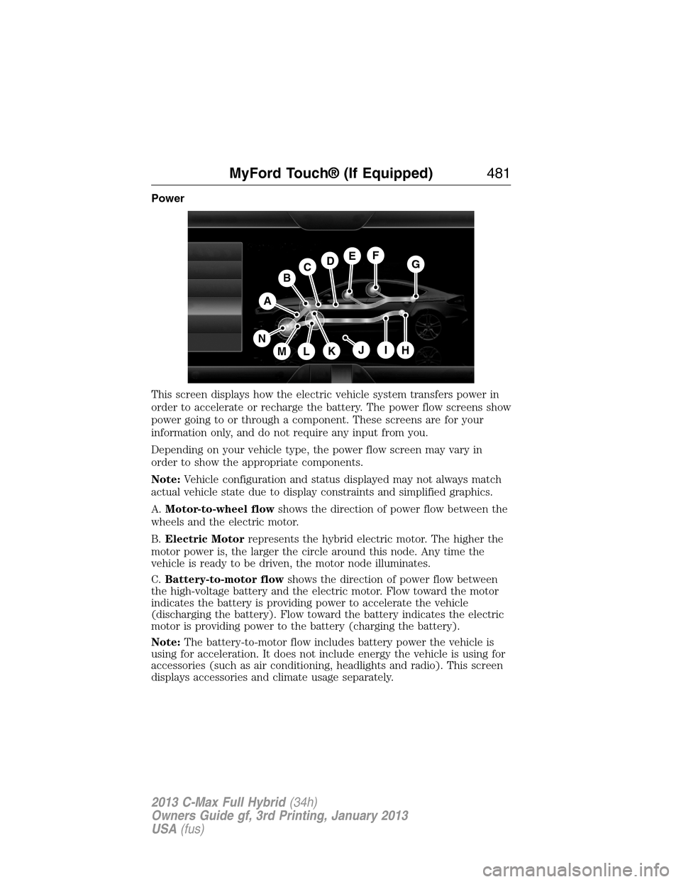
Power
This screen displays how the electric vehicle system transfers power in
order to accelerate or recharge the battery. The power flow screens show
power going to or through a component. These screens are for your
information only, and do not require any input from you.
Depending on your vehicle type, the power flow screen may vary in
order to show the appropriate components.
Note:Vehicle configuration and status displayed may not always match
actual vehicle state due to display constraints and simplified graphics.
A.Motor-to-wheel flowshows the direction of power flow between the
wheels and the electric motor.
B.Electric Motorrepresents the hybrid electric motor. The higher the
motor power is, the larger the circle around this node. Any time the
vehicle is ready to be driven, the motor node illuminates.
C.Battery-to-motor flowshows the direction of power flow between
the high-voltage battery and the electric motor. Flow toward the motor
indicates the battery is providing power to accelerate the vehicle
(discharging the battery). Flow toward the battery indicates the electric
motor is providing power to the battery (charging the battery).
Note:The battery-to-motor flow includes battery power the vehicle is
using for acceleration. It does not include energy the vehicle is using for
accessories (such as air conditioning, headlights and radio). This screen
displays accessories and climate usage separately.
A
H
DGEF
BC
IKMLJ
N
MyFord Touch® (If Equipped)481
2013 C-Max Full Hybrid(34h)
Owners Guide gf, 3rd Printing, January 2013
USA(fus)
Page 483 of 552
D.Plug (Energi only)appears when you plug your vehicle into the
wall. When charging the high voltage battery from the wall, you can see
flow from the plug to the battery on the screen.
•Accessoriesindicates electrical power demands from your vehicle’s
accessory systems. Accessories use power but do not contribute to
making the vehicle move. The power flow displays power usage from
the climate control system and other accessories separately.
E.Otherincludes all power usage from the low voltage accessories such
as the climate control fan, headlights and heated seats. The higher the
power usage is from these accessories, the larger the circle around the
node. This node illuminates anytime the vehicle is on since there is
always some low level power in use.
F.Climateincludes the power usage from the high-voltage climate
control components such as the electric A/C compressor and the electric
heater (Energi only). The higher the power usage is from these
components, the larger the circle around this node.
Note:The climate control system may determine A/C is necessary even
when you turn it off. In this case, you may see some climate power when
the A/C is off.
G.High voltage battery powerrepresents your high-voltage battery.
A circle illuminates around the node when the high-voltage battery is
receiving power from regenerative braking, engine charging or external
charging (when you plug it in). The higher the power usage is from the
high-voltage battery, the larger the circle around this node.
H.Fuelrepresents the fuel tank in the vehicle.
I.Fuel-to-engine flowshows flow from the fuel tank to the engine
when the engine is on and using fuel (there are some cases where the
engine is on, but not using any fuel). When the engine is on, but not
using fuel, the engine node is active, but the fuel flow path is off. An
example of this is when your foot is off the accelerator pedal and the
vehicle is traveling at a high speed.
J.Engine On due toprovides you with the reason(s) the gasoline
engine is on. When the gasoline engine is off, this display does not
appear.Engine On due toreasons displayed by the system are in a
chart following this list.
K.Motor-to-engine flowshows the direction of power flow between the
engine and the electric motor. The direction indicates if the engine is
providing power to the high-voltage electrical system, or if the high-voltage
electrical system is providing power to control or start the engine.
482MyFord Touch® (If Equipped)
2013 C-Max Full Hybrid(34h)
Owners Guide gf, 3rd Printing, January 2013
USA(fus)
Page 548 of 552
High-voltage battery
charging ...................................205
service disconnect ..................211
High-voltage shut off ................258
Hill start assist ..........................217
Homelink wireless control
system ........................................166
Hood ..........................................282
How to use voice commands ...438
I
Ignition ...............................175, 350
Illuminated visor mirror ...........103
Information displays .................114
Inspection/maintenance (I/M)
testing ........................................204
Instrument panel
cleaning ...................................314
cluster ......................................109
Intelligent Access Key ................59
J
Joining two calls
(multiparty/conference call) ....390
Jump-starting your vehicle ......259
K
Keyless entry system
autolock .....................................76
Keys .......................................58, 83
positions of the ignition .........175L
Lamps
bulb replacement
specifications chart ................309
fog lamps ...................................95
headlamps, flash to pass ..........92
interior lamps ...........................95
replacing bulbs .......302–303, 308
LATCH anchors ...........................28
Liftgate ............................74, 78–79
Lights, warning and indicator ..109
Listening to music ....................444
Load limits .................................241
Locks
autolock .....................................76
childproof ..................................32
doors ..........................................72
Lubricant specifications ...........351
Lug nuts ....................................349
M
Making and receiving calls .......467
MAP DVD - Loading and
Unloading ..................................467
Map icons ..................................520
Map mode ..................................518
Map preferences .......................517
Map updates ..............................521
Media Bluetooth menu options
(adding, connecting, deleting,
turning on/off) ..........................420
Message center .........................114
warning messages ...................127
Index547
2013 C-Max Full Hybrid(34h)
Owners Guide gf, 3rd Printing, January 2013
USA(fus)