check engine FORD C MAX HYBRID 2014 2.G Owner's Manual
[x] Cancel search | Manufacturer: FORD, Model Year: 2014, Model line: C MAX HYBRID, Model: FORD C MAX HYBRID 2014 2.GPages: 447, PDF Size: 8.06 MB
Page 144 of 447
5. Key off and complete refueling within
20 minutes. If more than 20 minutes is
required, close fuel door and repeat the
procedure.
This will enable you to refuel without any
issue.
Note: A fuel spill concern may occur if
overfilling the fuel tank. Do not overfill the
tank to the point that the fuel is able to
bypass the fuel filler nozzle. The overfilled
fuel may run down the drain located below
and in front of the fuel filler door.
If you did not close the fuel fill inlet
properly, a Check Fuel Fill Inlet message
may appear in the information display. At
the next opportunity, do the following:
1. Safely pull off the road.
2. Put the vehicle in park (P) and turn the
ignition off.
3. Open the fuel filler door and remove any visible debris from the fuel fill
opening.
4. Insert either the fuel fill nozzle or the fuel fill funnel provided with the vehicle
several times to allow the inlet to close
properly. This will dislodge any debris
preventing the inlet from sealing.
If this action corrects the problem, the
message may not reset immediately. It
may take several driving cycles for the
message to turn off. A driving cycle
consists of an engine start-up (after four
or more hours with the engine off) followed
by city and highway driving. Continuing to
drive with the message on may cause the
service engine soon lamp to turn on as
well. FUEL CONSUMPTION
Note:
The amount of usable fuel in the
empty reserve varies and should not be
relied upon to increase driving range. When
refueling your vehicle after the fuel gauge
indicates empty, you might not be able to
refuel the full amount of the advertised
capacity of the fuel tank due to the empty
reserve still present in the tank.
Empty reserve is the amount of fuel
remaining in the tank after the fuel gauge
indicates empty. Do not rely on this fuel for
driving. The usable capacity of the fuel
tank is the amount of fuel that can be put
into the tank after the gauge indicates
empty. The advertised capacity is the total
fuel tank size – it is the combined usable
capacity plus the empty reserve.
Filling the Tank
For consistent results when filling the fuel
tank:
• Turn the ignition off before fueling; an
inaccurate reading results if the engine
is left running.
• Use the same fill rate
(low-medium-high) each time the tank
is filled.
• Allow no more than two automatic
click-offs when filling.
Results are most accurate when the filling
method is consistent.
Calculating Fuel Economy
Do not measure fuel economy during the
first 1000 miles (1600 kilometers) of
driving (this is your engine ’s break-in
period); a more accurate measurement is
obtained after 2000 miles - 3000 miles
(3200 kilometers - 4800 kilometers). Also,
fuel expense, frequency of fill ups or fuel
gauge readings are not accurate ways to
measure fuel economy.
142
C-MAX (CCG) Fuel and Refueling
Page 146 of 447
Do not make any unauthorized changes to
your vehicle or engine. By law, vehicle
owners and anyone who manufactures,
repairs, services, sells, leases, trades
vehicles, or supervises a fleet of vehicles
are not permitted to intentionally remove
an emission control device or prevent it
from working. Information about your
vehicle
’s emission system is on the Vehicle
Emission Control Information Decal
located on or near the engine. This decal
also lists engine displacement
Please consult your warranty information
for complete details.
On-Board Diagnostics (OBD-II)
Your vehicle is equipped with a computer
that monitors the engine ’s emission control
system. This system is commonly known
as the on-board diagnostics system
(OBD-II). The OBD-II system protects the
environment by ensuring that your vehicle
continues to meet government emission
standards. The OBD-II system also assists
your authorized dealer in properly servicing
your vehicle. When the service engine soon
indicator illuminates, the OBD-II
system has detected a
malfunction. Temporary malfunctions may
cause the service engine soon indicator to
illuminate. Examples are:
1. The vehicle has run out of fuel —the
engine may misfire or run poorly.
2. Poor fuel quality or water in the fuel —the engine may misfire or run
poorly.
3. The fuel fill inlet may not have been properly closed. See Refueling (page
138).
4. Driving through deep water —the
electrical system may be wet. These temporary malfunctions can be
corrected by filling the fuel tank with good
quality fuel, properly closing the fuel fill
inlet or letting the electrical system dry out.
After three driving cycles without these or
any other temporary malfunctions present,
the service engine soon indicator should
stay off the next time the engine is started.
A driving cycle consists of a cold engine
startup followed by mixed city/highway
driving. No additional vehicle service is
required.
If the service engine soon indicator remains
on, have your vehicle serviced at the first
available opportunity. Although some
malfunctions detected by the OBD-II may
not have symptoms that are apparent,
continued driving with the service engine
soon indicator on can result in increased
emissions, lower fuel economy, reduced
engine and transmission smoothness, and
lead to more costly repairs.
Readiness for
Inspection/Maintenance (I/M)
Testing
Some state/provincial and local
governments may have
Inspection/Maintenance (I/M) programs
to inspect the emission control equipment
on your vehicle. Failure to pass this
inspection could prevent you from getting
a vehicle registration.
If the service engine soon
indicator is on or the bulb does
not work, the vehicle may need
to be serviced. See On-Board Diagnostics.
Your vehicle may not pass the I/M test if
the service engine soon indicator is on or
not working properly (bulb is burned out),
or if the OBD-II system has determined
that some of the emission control systems
have not been properly checked. In this
case, the vehicle is considered not ready
for I/M testing.
144
C-MAX (CCG) Fuel and Refueling
Page 147 of 447
If the vehicle
’s engine or transmission has
just been serviced, or the battery has
recently run down or been replaced, the
OBD-II system may indicate that the
vehicle is not ready for I/M testing. To
determine if the vehicle is ready for I/M
testing, turn the ignition key to the on
position for 15 seconds without cranking
the engine. If the service engine soon
indicator blinks eight times, it means that
the vehicle is not ready for I/M testing; if
the service engine soon indicator stays on
solid, it means that the vehicle is ready for
I/M testing.
The OBD-II system is designed to check
the emission control system during normal
driving. A complete check may take several
days. If the vehicle is not ready for I/M
testing, the following driving cycle
consisting of mixed city and highway
driving may be performed:
15 minutes of steady driving on an
expressway/highway followed by 20
minutes of stop-and-go driving with at
least four 30-second idle periods.
Allow the vehicle to sit for at least eight
hours with the ignition Off. Then, start the
vehicle and complete the above driving
cycle. The vehicle must warm up to its
normal operating temperature. Once
started, do not turn off the vehicle until the
above driving cycle is complete. If the
vehicle is still not ready for I/M testing, the
above driving cycle will have to be
repeated.
145
C-MAX (CCG) Fuel and Refueling
Page 158 of 447
GENERAL INFORMATION
Note:
Occasional brake noise is normal. If
a metal-to-metal, continuous grinding or
continuous squeal sound is present, the
brake linings may be worn-out. Have the
system checked by an authorized dealer. If
the vehicle has continuous vibration or
shudder in the steering wheel while braking,
have it checked by an authorized dealer.
Note: Brake dust may accumulate on the
wheels, even under normal driving
conditions. Some dust is inevitable as the
brakes wear and does not contribute to
brake noise. See Cleaning the Alloy
Wheels (page 236). See
Warning Lamps and
Indicators (page 83).
Wet brakes result in reduced braking
efficiency. Gently press the brake pedal a
few times when driving from a car wash or
standing water to dry the brakes.
Brake Over Accelerator
In the event the accelerator pedal
becomes stuck or entrapped, apply steady
and firm pressure to the brake pedal to
slow the vehicle and reduce engine power.
If you experience this condition, apply the
brakes and bring your vehicle to a safe
stop. Move the transmission selector lever
to position
P, switch the engine off and
apply the parking brake. Inspect the
accelerator pedal for any interference. If
none are found and the condition persists,
have your vehicle towed to the nearest
authorized dealer. Brake Assist
Brake assist detects when you brake
heavily by measuring the rate at which you
press the brake pedal. It provides
maximum braking efficiency as long as you
press the pedal. Brake assist can reduce
stopping distances in critical situations.
Anti-lock Brake System
This system helps you maintain steering
control during emergency stops by keeping
the brakes from locking.
This lamp momentarily
illuminates when you turn the
ignition on. If the light does not
illuminate during start up, remains on or
flashes, the system may be disabled. Have
the system checked by an authorized
dealer. If the system is disabled, normal
braking is still effective. If the
brake warning lamp illuminates
when you release the parking brake, have
the system checked by an authorized
dealer.
Regenerative Braking System
This feature is used to simulate the engine
braking of an internal combustion engine
and assist the standard brake system while
recovering some of the energy of motion
and storing it in the battery to improve fuel
economy. The standard brake system is
designed to fully stop the car if
regenerative braking is not available.
During regenerative braking, the motor is
spun as a generator to create electrical
current. This recharges the battery and
slows the vehicle. In effect, once the
accelerator pedal is released, the motor
changes from an energy user to an energy
producer.
156
C-MAX (CCG) BrakesE144522 E144522
Page 175 of 447
STEERING
Electric Power Steering
WARNINGS
The electric power steering system
has diagnostic checks that
continuously monitor the system to
ensure proper operation. When a system
error is detected a steering message will
appear in the information display. The electric power steering system
has diagnostic checks that
continuously monitor the system to
ensure proper operation of the electronic
system. When an electronic error is
detected, a message will be displayed in
the information display. If this happens,
stop the vehicle in a safe place, and turn
off the engine. After at least 10 seconds,
reset the system by restarting the engine,
and watch the information display for a
steering message. If a steering message
returns, or returns while driving, take the
vehicle to your dealer to have it checked. Obtain immediate service if a system
error is detected. You may not notice
any difference in the feel of your
steering, but a serious condition may exist.
Failure to do so may result in loss of
steering control. Your vehicle is equipped with an electric
power-assisted steering system. There is
no fluid reservoir to check or fill.
If your vehicle loses electrical power while
you are driving (or if the ignition is turned
off), you can steer the vehicle manually,
but it takes more effort. Extreme
continuous steering may increase the effort
it takes for you to steer. This occurs to
prevent internal overheating and
permanent damage to your steering system. If this should occur, you will neither
lose the ability to steer the vehicle
manually nor will it cause permanent
damage. Typical steering and driving
maneuvers will allow the system to cool
and steering assist will return to normal.
Steering Tips
If the steering wanders or pulls, check for:
•
an improperly inflated tire
• uneven tire wear
• loose or worn suspension components
• loose or worn steering components
• improper vehicle alignment
A high crown in the road or high crosswinds
may also make the steering seem to
wander or pull.
Adaptive Learning
The EPS system adaptive learning helps
correct for road irregularities and improves
overall handling and steering feel. It
communicates with the vehicle's brake
system to help operate advanced stability
control and accident avoidance systems.
Additionally, whenever the battery is
disconnected or a new battery installed,
the vehicle must be driven a short distance
before the strategy is relearned and all
systems are reactivated.
173
C-MAX (CCG) Driving Aids
Page 192 of 447
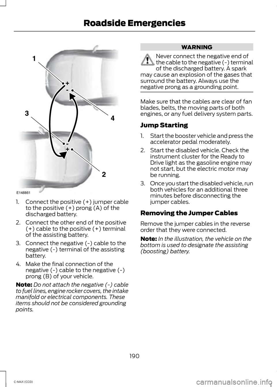
1.
Connect the positive (+) jumper cable
to the positive (+) prong (A) of the
discharged battery.
2. Connect the other end of the positive (+) cable to the positive (+) terminal
of the assisting battery.
3. Connect the negative (-) cable to the negative (-) terminal of the assisting
battery.
4. Make the final connection of the negative (-) cable to the negative (-)
prong (B) of your vehicle.
Note: Do not attach the negative (-) cable
to fuel lines, engine rocker covers, the intake
manifold or electrical components. These
items should not be considered grounding
points. WARNING
Never connect the negative end of
the cable to the negative (-) terminal
of the discharged battery. A spark
may cause an explosion of the gases that
surround the battery. Always use the
negative prong as a grounding point. Make sure that the cables are clear of fan
blades, belts, the moving parts of both
engines, or any fuel delivery system parts.
Jump Starting
1.
Start the booster vehicle and press the
accelerator pedal moderately.
2. Start the disabled vehicle. Check the instrument cluster for the Ready to
Drive light as the gasoline engine may
not start, but the electric motor may
be running.
3. Once you start the disabled vehicle, run
both vehicles for an additional three
minutes before disconnecting the
jumper cables.
Removing the Jumper Cables
Remove the jumper cables in the reverse
order that they were connected.
Note: In the illustration, the vehicle on the
bottom is used to designate the assisting
(boosting) battery.
190
C-MAX (CCG) Roadside EmergenciesE148861
Page 211 of 447
GENERAL INFORMATION
Have your vehicle serviced regularly to help
maintain its roadworthiness and resale
value. There is a large network of Ford
authorized dealers that are there to help
you with their professional servicing
expertise. We believe that their specially
trained technicians are best qualified to
service your vehicle properly and expertly.
They are supported by a wide range of
highly specialized tools developed
specifically for servicing your vehicle.
To help you service your vehicle, we
provide scheduled maintenance
information which makes tracking routine
service easy. See Scheduled
Maintenance (page 417).
If your vehicle requires professional service,
your authorized dealer can provide the
necessary parts and service. Check your
warranty information to find out which
parts and services are covered.
Use only recommended fuels, lubricants,
fluids and service parts conforming to
specifications. Motorcraft® parts are
designed and built to provide the best
performance in your vehicle.
Precautions
• Do not work on a hot engine.
• Make sure that nothing gets caught in
moving parts.
• Do not work on a vehicle with the
engine running in an enclosed space,
unless you are sure you have enough
ventilation.
• Keep all open flames and other burning
material (such as cigarettes) away
from the battery and all fuel related
parts. Working with the Engine Off
1. Set the parking brake and shift to
P
(Park).
2. Turn off the engine and remove the key
(if equipped).
3. Block the wheels.
Working with the Engine On WARNING
To reduce the risk of vehicle damage
and/or personal burn injuries, do not
start your engine with the air cleaner
removed and do not remove it while the
engine is running. 1. Set the parking brake and shift to
P
(Park).
2. Block the wheels
OPENING AND CLOSING THE
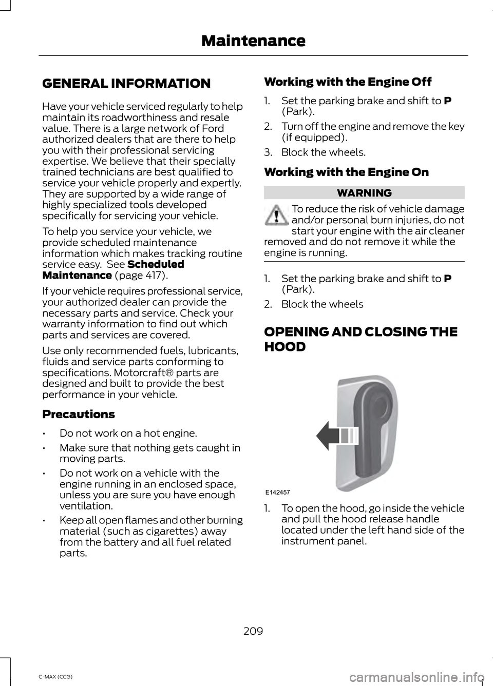
HOOD 1.
To open the hood, go inside the vehicle
and pull the hood release handle
located under the left hand side of the
instrument panel.
209
C-MAX (CCG) MaintenanceE142457
Page 213 of 447
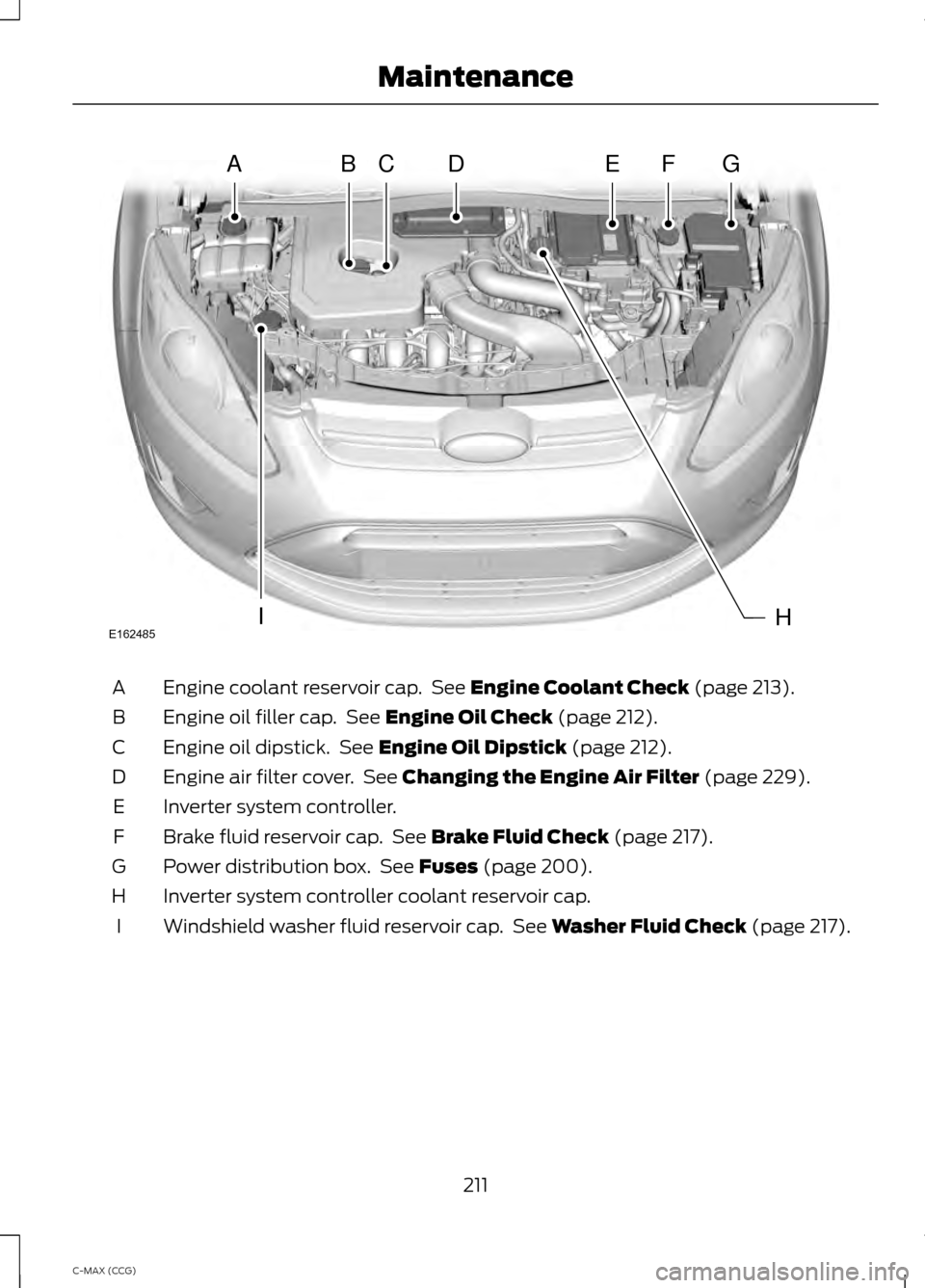
Engine coolant reservoir cap. See Engine Coolant Check (page 213).
A
Engine oil filler cap. See
Engine Oil Check (page 212).
B
Engine oil dipstick. See
Engine Oil Dipstick (page 212).
C
Engine air filter cover. See
Changing the Engine Air Filter (page 229).
D
Inverter system controller.
E
Brake fluid reservoir cap. See
Brake Fluid Check (page 217).
F
Power distribution box. See
Fuses (page 200).
G
Inverter system controller coolant reservoir cap.
H
Windshield washer fluid reservoir cap. See
Washer Fluid Check (page 217).
I
211
C-MAX (CCG) MaintenanceABCDEFG
HIE162485
Page 214 of 447
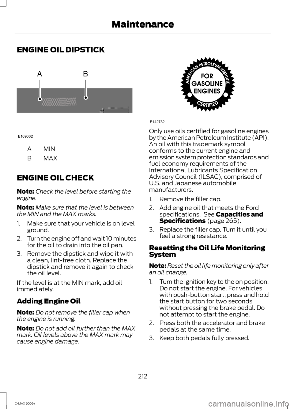
ENGINE OIL DIPSTICK
MINA
MAX
B
ENGINE OIL CHECK
Note: Check the level before starting the
engine.
Note: Make sure that the level is between
the MIN and the MAX marks.
1. Make sure that your vehicle is on level ground.
2. Turn the engine off and wait 10 minutes
for the oil to drain into the oil pan.
3. Remove the dipstick and wipe it with a clean, lint-free cloth. Replace the
dipstick and remove it again to check
the oil level.
If the level is at the MIN mark, add oil
immediately.
Adding Engine Oil
Note: Do not remove the filler cap when
the engine is running.
Note: Do not add oil further than the MAX
mark. Oil levels above the MAX mark may
cause engine damage. Only use oils certified for gasoline engines
by the American Petroleum Institute (API).
An oil with this trademark symbol
conforms to the current engine and
emission system protection standards and
fuel economy requirements of the
International Lubricants Specification
Advisory Council (ILSAC), comprised of
U.S. and Japanese automobile
manufacturers.
1. Remove the filler cap.
2. Add engine oil that meets the Ford
specifications. See Capacities and
Specifications (page 265).
3. Replace the filler cap. Turn it until you feel a strong resistance.
Resetting the Oil Life Monitoring
System
Note: Reset the oil life monitoring only after
an oil change.
1. Turn the ignition key to the on position.
Do not start the engine. For vehicles
with push-button start, press and hold
the start button for two seconds
without pressing the brake pedal. Do
not attempt to start the engine.
2. Press both the accelerator and brake pedals at the same time.
3. Keep both pedals fully pressed.
212
C-MAX (CCG) MaintenanceAB
E169062 E142732
Page 215 of 447
4. After three seconds, the Service: Oil
reset in prog. message will be
displayed.
5. After 25 seconds, the Service: Oil reset
complete message will be displayed.
6. Release both the accelerator and brake
pedals.
7. The Service: Oil reset complete message will no longer be displayed.
8. Rotate the key to the off position. For vehicles with push-button start, press
the start button to turn the vehicle off
completely.
ENGINE COOLANT CHECK
Engine Coolant and Inverter
System Controller Coolant
Your vehicle is equipped with two separate
cooling systems. One is for cooling the
engine and one is for cooling the inverter
system controller that is specific to the
hybrid operating system. The two systems
operate similarly, with the inverter system
controller cooling system generally
operating at a lower temperature and
pressure.
Checking the Engine Coolant
When the engine is cold, check the
concentration and level of the engine
coolant at the intervals listed in the
scheduled maintenance information. See
Scheduled Maintenance (page 417).
Note: Make sure that the level is between
the MIN and MAX marks on the engine
coolant reservoir.
Note: Coolant expands when it is hot. The
level may extend beyond the MAX mark.
Note: If the level is at the MIN mark, below
the MIN mark, or empty, add prediluted
coolant immediately. See
Adding Engine
Coolant in this chapter. The coolant concentration should be
maintained within 48% to 50%, which
equates to a freeze point between -30°F
(-34°C) and -34°F (-37°C).
Note:
For best results, coolant
concentration should be tested with a
refractometer such as Rotunda tool
300-ROB75240 available from your dealer.
Ford does not recommend the use of
hydrometers or coolant test strips for
measuring coolant concentrations.
Note: Automotive fluids are not
interchangeable. Do not use engine coolant
or antifreeze or windshield washer fluid
outside of its specified function and vehicle
location.
Checking the Inverter System
Controller Coolant
When the engine is cold, check the
concentration and level of the inverter
system controller coolant at the intervals
listed in the scheduled maintenance
information. See
Scheduled
Maintenance (page 417).
Note: Make sure that the level is between
the MIN and MAX marks on the inverter
system controller coolant reservoir.
Note: Coolant expands when it is hot. The
level may extend beyond the MAX mark.
Note: If the level is at the MIN mark, below
the MIN mark, or empty, add prediluted
coolant immediately. See
Adding Inverter
System Controller Coolant in this chapter.
The coolant concentration should be
maintained within 48% to 50%, which
equates to a freeze point between -30°F
(-34°C) and -34°F (-37°C).
213
C-MAX (CCG) Maintenance