warning FORD C MAX HYBRID 2014 2.G Manual PDF
[x] Cancel search | Manufacturer: FORD, Model Year: 2014, Model line: C MAX HYBRID, Model: FORD C MAX HYBRID 2014 2.GPages: 447, PDF Size: 8.06 MB
Page 145 of 447
1.
Fill the fuel tank completely and record
the initial odometer reading.
2. Each time you fill the tank, record the amount of fuel added.
3. After at least three to five tank fill ups, fill the fuel tank and record the current
odometer reading.
4. Subtract your initial odometer reading from the current odometer reading.
5. Calculate fuel economy by dividing miles traveled by gallons used (For
Metric: Multiply liters used by 100, then
divide by kilometers traveled).
Keep a record for at least one month and
record the type of driving (city or highway).
This provides an accurate estimate of the
vehicle ’s fuel economy under current
driving conditions. Additionally, keeping
records during summer and winter show
how temperature impacts fuel economy.
In general, lower temperatures mean lower
fuel economy.
EMISSION CONTROL SYSTEM WARNINGS
Do not park, idle, or drive your vehicle
in dry grass or other dry ground cover.
The emission system heats up the
engine compartment and exhaust system,
which can start a fire. Exhaust leaks may result in entry of
harmful and potentially lethal fumes
into the passenger compartment. If
you smell exhaust fumes inside your
vehicle, have your dealer inspect your
vehicle immediately. Do not drive if you
smell exhaust fumes. Your vehicle is equipped with various
emission control components and a
catalytic converter that will enable your
vehicle to comply with applicable exhaust
emission standards. To make sure that the
catalytic converter and other emission
control components continue to work
properly:
To make sure that the catalytic converter
and other emission control components
continue to work properly:
•
Use only the specified fuel listed.
• Avoid running out of fuel.
• Do not turn off the ignition while your
vehicle is moving, especially at high
speeds.
• Have the items listed in scheduled
maintenance information performed
according to the specified schedule.
The scheduled maintenance items listed
in scheduled maintenance information are
essential to the life and performance of
your vehicle and to its emissions system
If other than Ford, Motorcraft or
Ford-authorized parts are used for
maintenance replacements or for service
of components affecting emission control,
such non-Ford parts should be equivalent
to genuine Ford Motor Company parts in
performance and durability.
Illumination of the service engine soon
indicator, charging system warning light or
the temperature warning light, fluid leaks,
strange odors, smoke or loss of engine
power could indicate that the emission
control system is not working properly.
An improperly operating or damaged
exhaust system may allow exhaust to
enter the vehicle. Have a damaged or
improperly operating exhaust system
inspected and repaired immediately.
143
C-MAX (CCG) Fuel and Refueling
Page 148 of 447
GENERAL INFORMATION
WARNING
Have the battery pack serviced only
by an authorized electric vehicle
technician. Improper handling can
result in personal injury or death. Note:
The high-voltage battery does not
require regular service maintenance. Your vehicle consists of various
high-voltage components and wiring. All
of the high-voltage power flows through
specific wiring assemblies labeled as such
or covered with a solid orange convolute,
orange striped tape or both. Do not come
in contact with these components.
The high-voltage battery system is a
high-voltage, lithium-ion battery system.
The pack is located in the rear cargo area.
The high-voltage battery system uses an
air cooled system to regulate the
high-voltage battery temperature and help
maximize high-voltage battery life.Note:
The high-voltage battery is equipped
with air vents in the package tray that help
to regulate its temperature. It is important
to keep these openings free of obstructions.
Do not block the flow of cabin air to this
area.
HIGH-VOLTAGE SERVICE
DISCONNECT
The high-voltage service disconnect turns
off power from the high-voltage battery. Note:
There is a disconnect circuit in your
vehicle. Disconnecting the circuit will
automatically disable the high-voltage
battery.
To disable the battery and stop all
high-voltage electric activity in the vehicle
you can access high-voltage disconnect
circuit. To do this, you must unplug the
circuit from the circuit port connected to
the battery.
146
C-MAX (CCG) High Voltage BatteryE163462
Page 150 of 447
5.
Pull the handle toward you and remove
the service disconnect from the vehicle
to disable the high-voltage battery.
Reactivating the High-Voltage Battery
Note: If you have manually disconnected
your high-voltage shut off circuit, you will
need to reconnect the circuit before you can
reactivate it. The system will detect if the
electrical system is safe and turn on
automatically.
CHARGING THE HIGH
VOLTAGE BATTERY (IF EQUIPPED)
CHARGING THE HIGH-VOLTAGE
BATTERY (ENERGI VEHICLES) WARNINGS
Do not use the 120-volt convenience
cord with an extension cord or
adapter.
In Canada, do not use the 120-volt
convenience cord in commercial
garages.
This equipment has arcing or
sparking parts, do not expose to
flammable vapors. Position this
equipment at least 18 inches (80
millimeters) above the floor. Charging Equipment
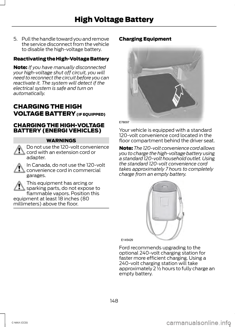
Your vehicle is equipped with a standard
120-volt convenience cord located in the
floor compartment behind the driver seat.
Note:
The 120-volt convenience cord allows
you to charge the high-voltage battery using
a standard 120-volt household outlet. Using
the standard 120-volt convenience cord
takes approximately 7 hours to completely
charge from an empty battery. Ford recommends upgrading to the
optional 240-volt charging station for
faster more efficient charging. Using a
240-volt charging station will take
approximately 2 ½ hours to fully charge an
empty battery.
148
C-MAX (CCG) High Voltage BatteryE78097 E145429
Page 155 of 447
AUTOMATIC TRANSMISSION
WARNINGS
Always set the parking brake fully
and make sure the gearshift is
latched in P (Park). Turn the ignition
to the off position and remove the key
whenever you leave your vehicle. Do not apply the brake pedal and
accelerator pedal simultaneously.
Applying both pedals simultaneously
for more than three seconds will limit
engine rpm, which may result in difficulty
maintaining speed in traffic and could lead
to serious injury. Automatic Transmission
Putting your vehicle in gear:
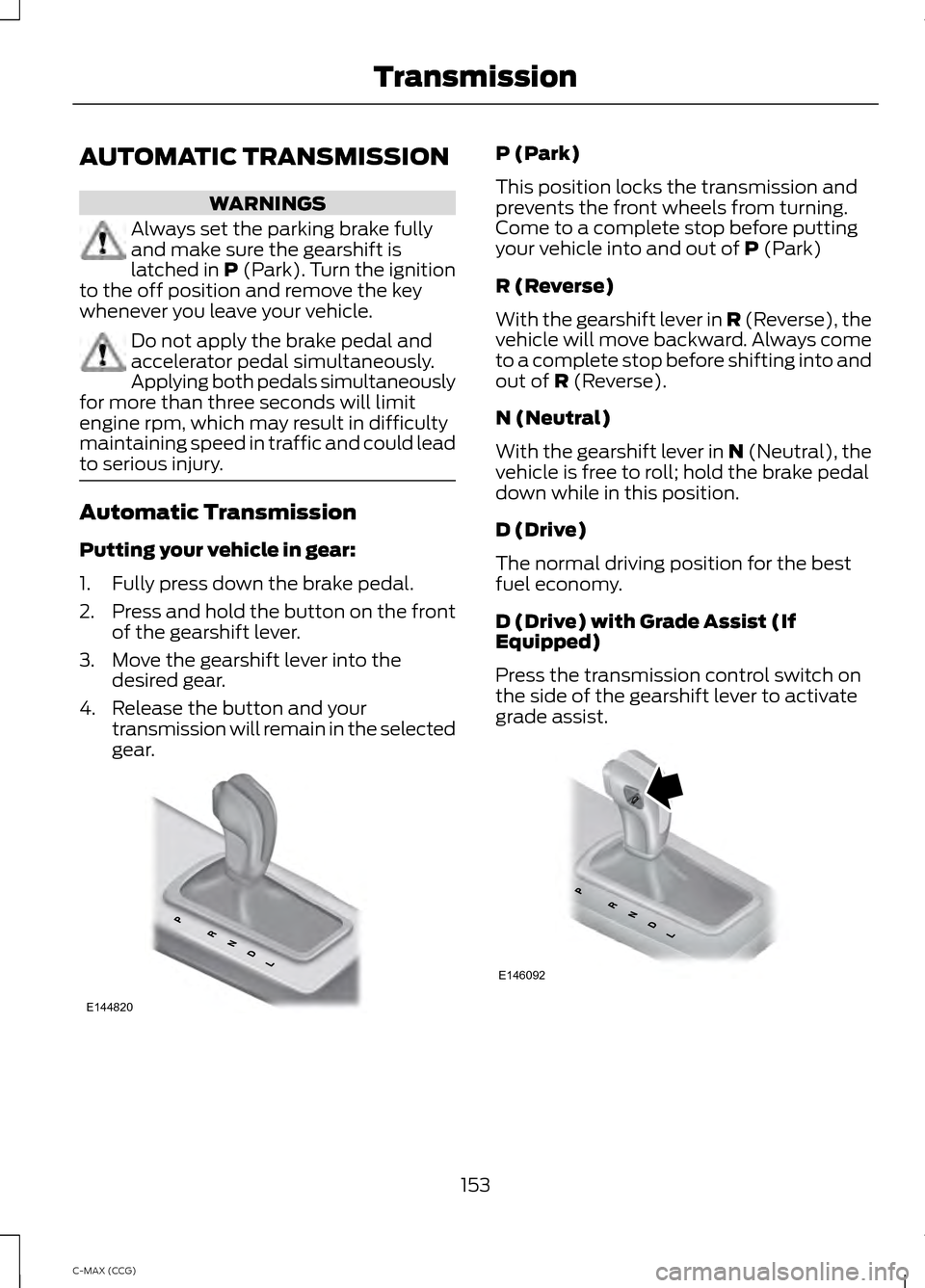
1. Fully press down the brake pedal.
2.
Press and hold the button on the front
of the gearshift lever.
3. Move the gearshift lever into the desired gear.
4. Release the button and your transmission will remain in the selected
gear. P (Park)
This position locks the transmission and
prevents the front wheels from turning.
Come to a complete stop before putting
your vehicle into and out of P (Park)
R (Reverse)
With the gearshift lever in R (Reverse), the
vehicle will move backward. Always come
to a complete stop before shifting into and
out of
R (Reverse).
N (Neutral)
With the gearshift lever in N (Neutral), the
vehicle is free to roll; hold the brake pedal
down while in this position.
D (Drive)
The normal driving position for the best
fuel economy.
D (Drive) with Grade Assist (If
Equipped)
Press the transmission control switch on
the side of the gearshift lever to activate
grade assist. 153
C-MAX (CCG) TransmissionE144820 E146092
Page 156 of 447
Grade assist:
•
Provides additional grade braking with
a combination of engine motoring and
high-voltage battery charging to help
maintain vehicle speed when
descending a grade.
• As the vehicle determines the amount
of engine motoring and high-voltage
battery charging, you may notice the
engine speed increasing and
decreasing to help maintain your
vehicle speed when descending a
grade.
• The grade assist lamp in the instrument
cluster is illuminated. The grade assist lamp will
appear in the instrument cluster
when grade assist is turned on.
Press the transmission control switch
again to return to normal D (Drive).
L (Low)
• Provides maximum engine braking.
• The transmission may be shifted into
L
(Low) at any vehicle speed.
Brake-Shift Interlock WARNINGS
Do not drive your vehicle until you
verify that the brake lamps are
working.
When doing this procedure, you will
be taking the vehicle out of park
which means the vehicle can roll
freely. To avoid unwanted vehicle
movement, always fully set the parking
brake prior to doing this procedure. Use
wheel chocks if appropriate. If the parking brake is fully released,
but the brake warning lamp remains
illuminated, the brakes may not be
working properly. See your authorized
dealer. Note:
See your authorized dealer as soon
as possible if this procedure is used.
Note: For some markets this feature will be
disabled.
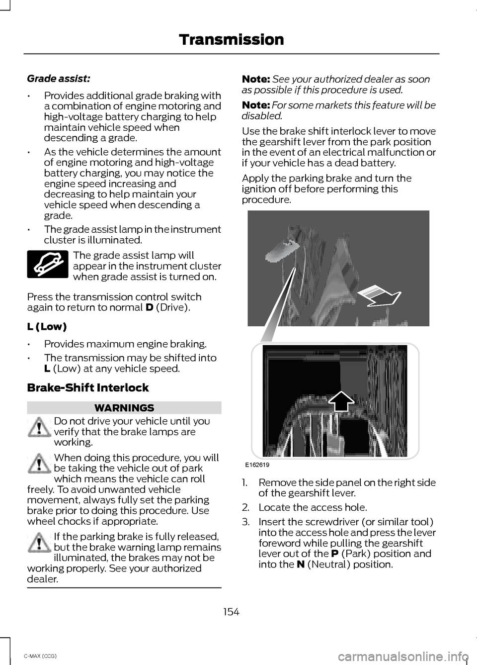
Use the brake shift interlock lever to move
the gearshift lever from the park position
in the event of an electrical malfunction or
if your vehicle has a dead battery.
Apply the parking brake and turn the
ignition off before performing this
procedure. 1.
Remove the side panel on the right side
of the gearshift lever.
2. Locate the access hole.
3. Insert the screwdriver (or similar tool) into the access hole and press the lever
foreword while pulling the gearshift
lever out of the
P (Park) position and
into the N (Neutral) position.
154
C-MAX (CCG) TransmissionE144523 E162619
Page 158 of 447
GENERAL INFORMATION
Note:
Occasional brake noise is normal. If
a metal-to-metal, continuous grinding or
continuous squeal sound is present, the
brake linings may be worn-out. Have the
system checked by an authorized dealer. If
the vehicle has continuous vibration or
shudder in the steering wheel while braking,
have it checked by an authorized dealer.
Note: Brake dust may accumulate on the
wheels, even under normal driving
conditions. Some dust is inevitable as the
brakes wear and does not contribute to
brake noise. See Cleaning the Alloy
Wheels (page 236). See
Warning Lamps and
Indicators (page 83).
Wet brakes result in reduced braking
efficiency. Gently press the brake pedal a
few times when driving from a car wash or
standing water to dry the brakes.
Brake Over Accelerator
In the event the accelerator pedal
becomes stuck or entrapped, apply steady
and firm pressure to the brake pedal to
slow the vehicle and reduce engine power.
If you experience this condition, apply the
brakes and bring your vehicle to a safe
stop. Move the transmission selector lever
to position
P, switch the engine off and
apply the parking brake. Inspect the
accelerator pedal for any interference. If
none are found and the condition persists,
have your vehicle towed to the nearest
authorized dealer. Brake Assist
Brake assist detects when you brake
heavily by measuring the rate at which you
press the brake pedal. It provides
maximum braking efficiency as long as you
press the pedal. Brake assist can reduce
stopping distances in critical situations.
Anti-lock Brake System
This system helps you maintain steering
control during emergency stops by keeping
the brakes from locking.
This lamp momentarily
illuminates when you turn the
ignition on. If the light does not
illuminate during start up, remains on or
flashes, the system may be disabled. Have
the system checked by an authorized
dealer. If the system is disabled, normal
braking is still effective. If the
brake warning lamp illuminates
when you release the parking brake, have
the system checked by an authorized
dealer.
Regenerative Braking System
This feature is used to simulate the engine
braking of an internal combustion engine
and assist the standard brake system while
recovering some of the energy of motion
and storing it in the battery to improve fuel
economy. The standard brake system is
designed to fully stop the car if
regenerative braking is not available.
During regenerative braking, the motor is
spun as a generator to create electrical
current. This recharges the battery and
slows the vehicle. In effect, once the
accelerator pedal is released, the motor
changes from an energy user to an energy
producer.
156
C-MAX (CCG) BrakesE144522 E144522
Page 159 of 447
When the accelerator pedal is released or
the brake pedal is applied, the brake
controller automatically detects the
amount of deceleration requested and
optimizes how much of the deceleration
will be produced by regenerative braking.
The remaining portion is generated by
standard friction braking. When the battery
is almost fully charged, the amount of
regenerative braking is limited to avoid
overcharging, and the requested
deceleration is produced by standard
friction braking alone.
Regenerative braking does not take the
place of the standard friction brakes; it only
assists them. Regenerative braking has
also been designed to interact with the
anti-lock brake system. Regenerative
braking is disabled when the anti-lock
brake system is activated or the battery is
fully charged.
HINTS ON DRIVING WITH
ANTI-LOCK BRAKES
Note:
When the system is operating, the
brake pedal will pulse and may travel
further. Maintain pressure on the brake
pedal. You may also hear a noise from the
system. This is normal.
The anti-lock braking system will not
eliminate the risks when:
• you drive too closely to the vehicle in
front of you
• your vehicle is hydroplaning
• you take corners too fast
• the road surface is poor. PARKING BRAKE WARNING
Always set the parking brake fully
and leave your vehicle with the
transmission selector lever in
position P. Note:
Do not press the release button while
pulling the lever up.
To apply the parking brake:
1. Press the foot brake pedal firmly.
2. Pull the parking brake lever up to its fullest extent.
Note: If you park your vehicle on a hill and
facing uphill, move the transmission selector
lever to position
P and turn the steering
wheel away from the curb.
Note: If you park your vehicle on a hill and
facing downhill, move the transmission
selector lever to
P and turn the steering
wheel toward the curb.
To release the parking brake:
1. Press the brake pedal firmly.
2. Pull the lever up slightly.
3. Press the release button and push the lever down.
HILL START ASSIST WARNINGS
The system does not replace the
parking brake. When you leave your
vehicle, always apply the parking
brake and put the transmission in park (P). You must remain in your vehicle once
you have activated the system.
During all times, you are responsible
for controlling your vehicle,
supervising the system and
intervening, if required.
157
C-MAX (CCG) Brakes
Page 160 of 447
WARNINGS
If the engine is revved excessively, or
if a malfunction is detected, the
system will be deactivated.
The system makes it easier to pull away
when your vehicle is on a slope without the
need to use the parking brake.
When the system is active, your vehicle will
remain stationary on the slope for two to
three seconds after you release the brake
pedal. This allows you time to move your
foot from the brake to the accelerator
pedal. The brakes are released
automatically once the engine has
developed sufficient drive to prevent your
vehicle from rolling down the slope. This
is an advantage when pulling away on a
slope, (for example from a car park ramp,
traffic lights or when reversing uphill into
a parking space).
The system will activate automatically on
any slope that will cause significant vehicle
rollback.
Using Hill Start Assist
1. Press the brake pedal to bring your
vehicle to a complete standstill. Keep
the brake pedal pressed.
2. If the sensors detect that your vehicle is on a slope, the system will activate
automatically.
3. When you remove your foot from the brake pedal, your vehicle will remain
on the slope without rolling away for
about two or three seconds. This hold
time will automatically be extended if
you are in the process of driving off.
4. Drive off in the normal manner. The brakes will release automatically.
158
C-MAX (CCG) Brakes
Page 161 of 447
PRINCIPLE OF OPERATION
The traction control system helps avoid
drive wheel spin and loss of traction.
If your vehicle begins to slide, the system
applies the brakes to individual wheels
and, when needed, reduces engine power
at the same time. If the wheels spin when
accelerating on slippery or loose surfaces,
the system reduces engine power in order
to increase traction.
USING TRACTION CONTROL
In certain situations for example, stuck in
snow or mud, turning the traction control
off may be beneficial as this allows the
wheels to spin with full engine power.
Depending on the type of system you have
on your vehicle, you can either turn the
system off using the information display
or by pressing the button.
Switching the System Off Using
the Information Display Controls
(If Equipped)
Your vehicle comes with this feature
already enabled. If required, you can switch
this feature off using the information
display controls. See Principle of
Operation (page 159).
Switching the System Off Using a
Switch
(If Equipped)
The button is located in the instrument
panel.
Press the button. You will see a message
in conjunction with an illuminated icon in
the display. Press the button again to
return the system to normal mode.
When you switch the traction control
system off, stability control remains fully
active. System Indicator Lights and
Messages WARNING
If a failure has been detected within
the AdvanceTrac system, the
stability control light will illuminate
steadily. Verify that the AdvanceTrac
system was not manually disabled through
the information display. If the stability
control light still illuminates steadily, have
the system serviced by an authorized
dealer immediately. Operating your vehicle
with AdvanceTrac disabled could lead to
an increased risk of loss of vehicle control,
vehicle rollover, personal injury and death. The stability control light
temporarily illuminates on
engine start-up and flashes
when a driving condition activates the
stability system. The stability control off light
temporarily illuminates on
engine start-up and stays on
when you turn the traction control system
off.
When you turn the traction control system
off or on, a message appears in the
information display showing system status.
159
C-MAX (CCG) Traction ControlE138639
Page 162 of 447
PRINCIPLE OF OPERATION
WARNINGS
Vehicle modifications involving
braking system, aftermarket roof
racks, suspension, steering system,
tire construction and wheel and tire size
may change the handling characteristics
of your vehicle and may adversely affect
the performance of the AdvanceTrac
system. In addition, installing any stereo
loudspeakers may interfere with and
adversely affect the AdvanceTrac system.
Install any aftermarket stereo loudspeaker
as far as possible from the front center
console, the tunnel, and the front seats in
order to minimize the risk of interfering with
the AdvanceTrac sensors. Reducing the
effectiveness of the AdvanceTrac system
could lead to an increased risk of loss of
vehicle control, vehicle rollover, personal
injury and death. Remember that even advanced
technology cannot defy the laws of
physics. It’
s always possible to lose
control of a vehicle due to inappropriate
driver input for the conditions. Aggressive
driving on any road condition can cause
you to lose control of your vehicle
increasing the risk of personal injury or
property damage. Activation of the
AdvanceTrac system is an indication that
at least some of the tires have exceeded
their ability to grip the road; this could
reduce the operator ’s ability to control the
vehicle potentially resulting in a loss of
vehicle control, vehicle rollover, personal
injury and death. If your AdvanceTrac
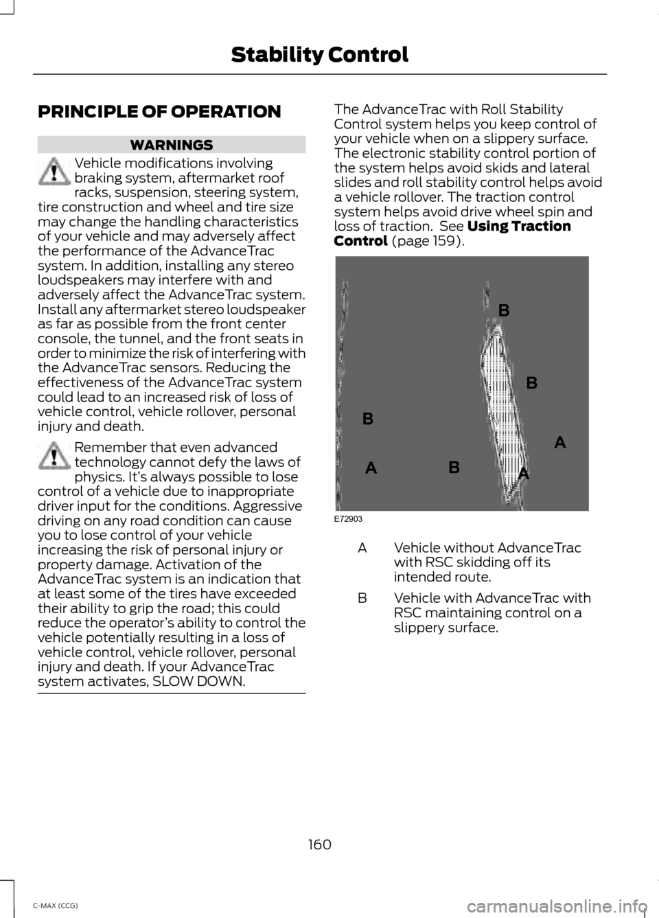
system activates, SLOW DOWN. The AdvanceTrac with Roll Stability
Control system helps you keep control of
your vehicle when on a slippery surface.
The electronic stability control portion of
the system helps avoid skids and lateral
slides and roll stability control helps avoid
a vehicle rollover. The traction control
system helps avoid drive wheel spin and
loss of traction. See Using Traction
Control (page 159). Vehicle without AdvanceTrac
with RSC skidding off its
intended route.
A
Vehicle with AdvanceTrac with
RSC maintaining control on a
slippery surface.
B
160
C-MAX (CCG) Stability ControlE72903A
AA
B
BB
B