oil level FORD CAPRI 1974 Owner's Manual
[x] Cancel search | Manufacturer: FORD, Model Year: 1974, Model line: CAPRI, Model: FORD CAPRI 1974Pages: 205, PDF Size: 43.75 MB
Page 125 of 205
Chapter 6 Manual gearbo x and auto m atic transmission
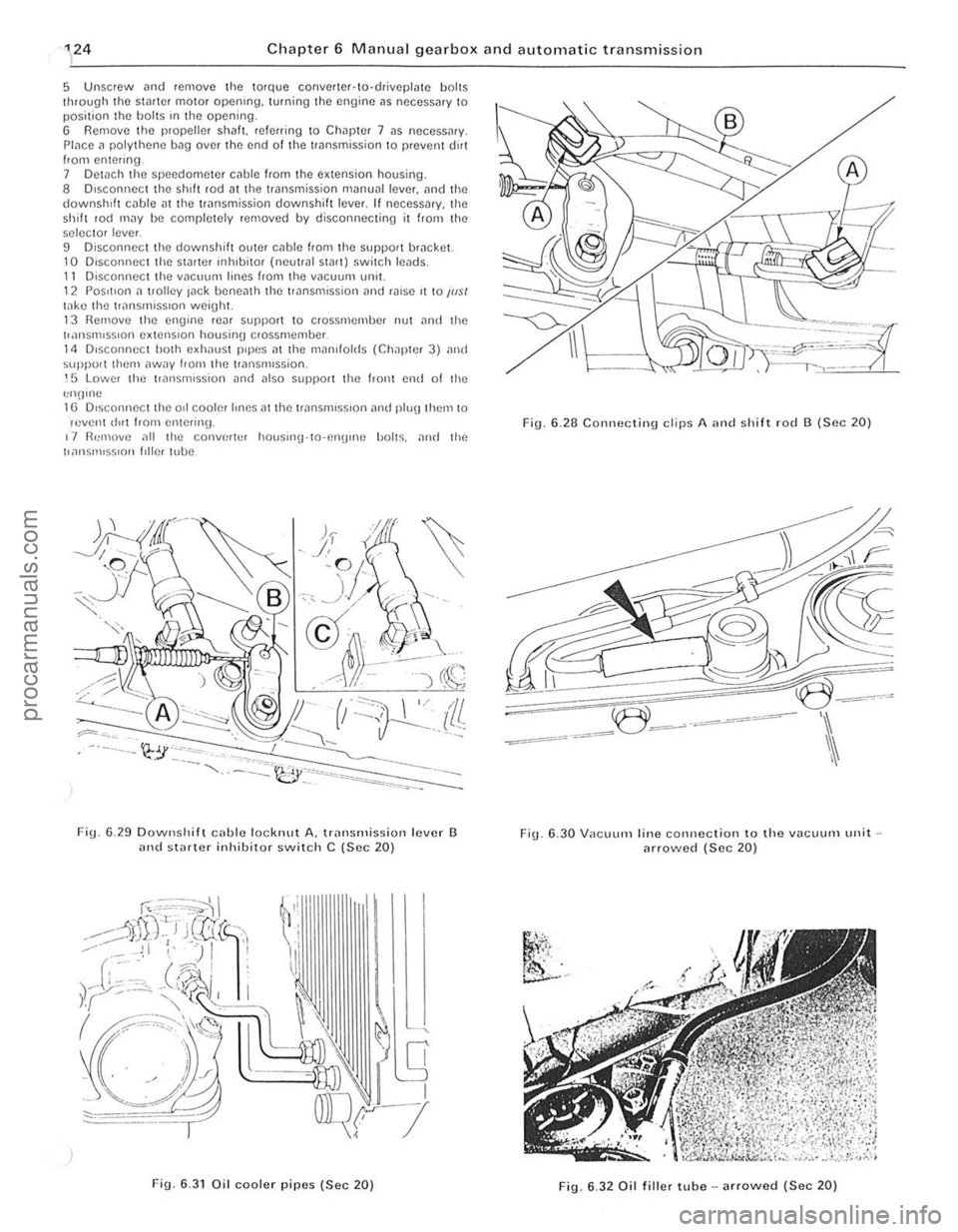
5 Unsc rew and remove the tolque conve rter·to·driv eplme b ol ts
t h rough the stader mot o r openrng. turning the engine ,1S neces sary to position the holts rn the opening.
6 Rem ove the propel ler s h alt. reI erring 1 0 Chap te r 7 as necess,u y.
Place a po ly thene bag over the end of t he transmiss io n to preven t dirt Irom ente ring. 7 Detach the sp eedome te r cable from I he extension housing .
8 D iscon nec t the shIft rod althe trans miss ion manual lever. an d the downshift c
selec to r level.
D D isconnect the downshift ouler cable hom the support bracket. 10 D,SCOI1l10Ct th e StMter rnhlbilOr (noullal Start) switch leads. II Disconnoctthe vacuum lines from the vacuunl unll. 1 2 POSItion a Irolley lac k bcne
Fig. 6 .2 8 C onnecting d ips A ,m d shift ro d B (SIlC 20)
-=<
~:=~~3
-: _~e~~-=--'
Fig . 6.30 V ilCUUI11 line connection to the vilcuum unit arrowed (Sec 20)
.... ,' ,',.<.
~
"i'i.
~' ..
F ig . 6.32 Oil fil ler tube - arrowed (Sec 20)
procarmanuals.com
Page 126 of 205
Chapter 6 Manual gearbox and automatic transmission 125
18 Carefully ~ove the lrilnsmission reilrwards ilnd downwmds, and
away from the car. Make sur e that lhe torque conver ter rema ins fully in
the transmission. 19 Refilling is the reverse of remova l but ensure that the torque converter drain plug is In line wIth the hole in the driveplate . To check
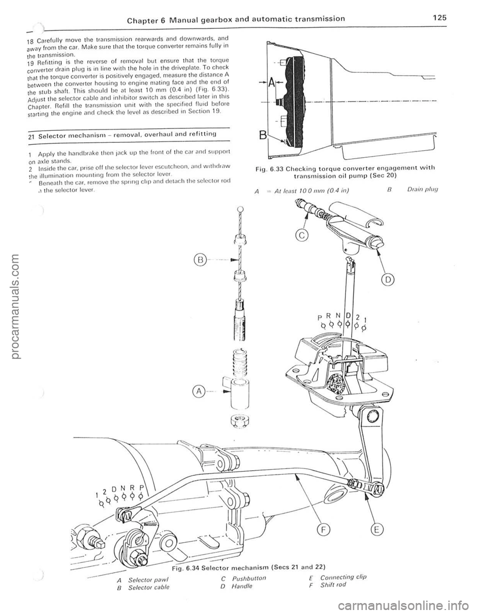
that the torque converter is positively engaged. measure the distance A between the converter housing to engine mJting fJce and the end of the $llIb ShilfL This should be al leilsl 10 mm (0.4 in) (Fig. 633). Adjust the selector cilble i1nd inhlbilOr switch i1S deSCribed later ill this Chapter. Reftll the 1riln smission unit with lhe specified flu,d before StDrlll1g the ennine i1nd check lhe level i1S describe(f in Section 19.
21 Selecto r mechililism -removnl. overhnlll ilud refitting
Apply the hnndbr,lke then Inek up the front of the car ilntl suppo'1
on ilxle stands. 2 Insi(fe the cm. prose off th e selector lever escutcheon. ,md wothrhaw
!he Illumillnt,on 1ll0U1l1l1l\J from the selec tor lever Oeneilth the CM. remove the Spr
r(
®---i
A
6 .33 Checking torque converter engagement with trnnsmission oil pump (Sec 20)
Alle,1S1 100111111 (0.4 ill) 8 O(.1ill (lluy
:-----
--
6 .34 Selector mechanism (Secs 2 1 and 22)
A SclcclOf pawl B SClccrof cabie
C Pusllbu/loll
o Natld/c
f Connccting clip F Shill (od
.'
. 1 , ;
I
procarmanuals.com
Page 134 of 205
1 Chapter 8 Rear axle 133
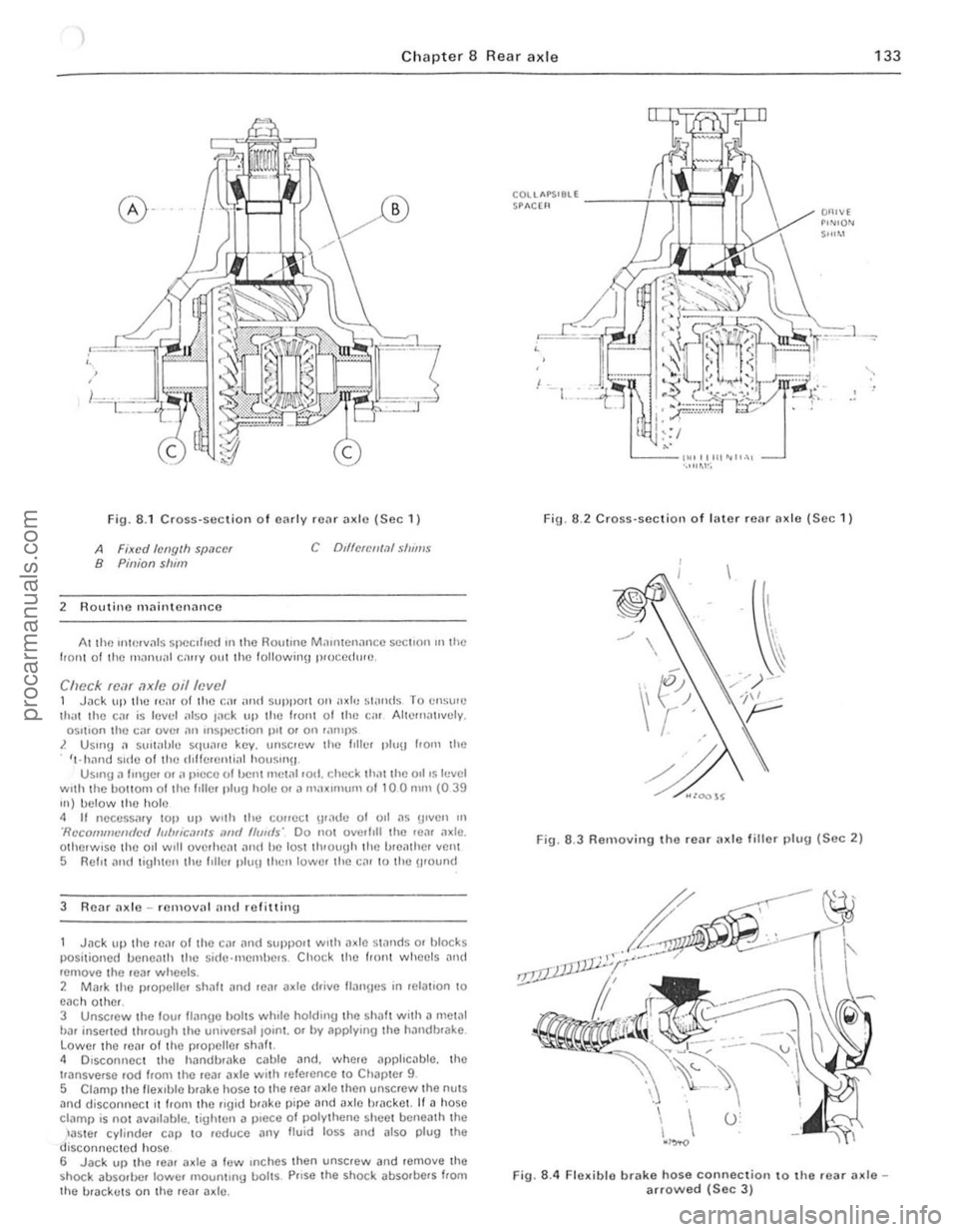
Fig. 8 .1 CrOSS-Sl!ction o f cnrlv rCilr ;1xlo (Sec 1)
A Fixed /ellglh SIJ.1C(!f B Pinion slum
2 Routino mnintcnoncc
C Dd1clCII1.11 S/II"'$
At lhe uHerv"ls specIfIed 111 the HOlltmc M.111l1cn;mc c SCCllon III the 110111 0 1 the mnnu;1I c""y oul the following p,uccdw(!.
Check fcar axle oil level 1 Jilek lIlllhc IvaI of the Cil! ;uHf suPPOtl on axle ~I"nds T o C!lSI'''') li1,'l Ihe Cilr is lellel ;,150 I
3 R e
posi tioned lIancnlh the sid(Hllemhe.s . Cho ck thc tronl wheels and rcmove the .ear wheelS . 2 Mark thc p.ol>elle. sh;J1! ilnd .eil'
t'ansverse ,od from the .ea. (Ide wl,h refalCnce 10 Chal >!el 9
5 CI
COUAPS'8ll -----i--i!~e"'.!i SPACH'
,
Fig. 6 .2 Cross·sc ction of I"ter rear Ilxle (See 1)
Fig. 6.3 Removing the rear ax le fillo r 1)lug (Sec 2)
Fig. 8.4 Flexible brake hose connection to the .ear axlearrowed (Sec 3 )
procarmanuals.com
Page 135 of 205
1
134 Chapte r 8 Rea r axl e
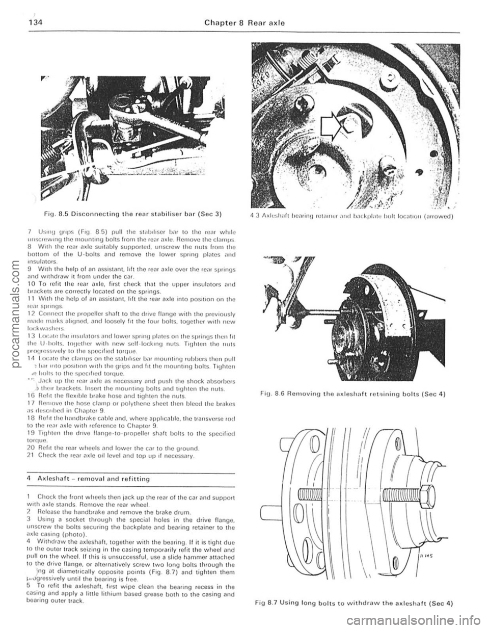
FiO. 8.5 Discorlllccti!l9 the rcar sI"biliser Iwr (Sec 3)
7 U~"'!I u"ps (FlU 8 5) I)UU rile s1.1h,l,s(lI b.ll 10 lilt:! lCol. while unstocwIIlIJ the mOlllllnlU I)oIIS from the Ie;)' ;l~II!. flcl110vc the C!JIllI'S 8 W,lh the rC:II Ildc sUlt,lbly SUIlI>o.ICd. lIIlSCICW rhe nulS hom the hallom 01 the U-bolts i1rld reOlOlle rhe lowel S I)llrlU p l;lrcs .. ",t! 1115 .. 1<11015. 9 Wllh rhe help of an asslSlilnt. hft the rem a~lc over the "~
Chock Ihe front wheels then jack up the re,lr of the c~r ilnd support with onle stilnds. Remove the .ear wheel 2 Ilelea se the hilndb.nke and .emove Ihe brake drum.
3 USIng a socket through the special holes in the drive lI.::tnge. unsc'ew the bollS secu.ing the b.::tckp late and bearing ,el.::tinor to tho a~le cilSln g (pholo). 11 Withdraw tho a~leshnft. together with the bearing. " it is tight due 10 tho oulor Ir
ig. 8
.6 RelHoving t h o Mdeshalt .e l'l ining hoits (Soc 4)
If
I
/1
II
I
\,
Fig 8 .7 U sing long bolls to ""ithdra"" tho a~leshaft (Sec 4)
cd
procarmanuals.com
Page 136 of 205
m
)
Chapter 8 Rear axle 135
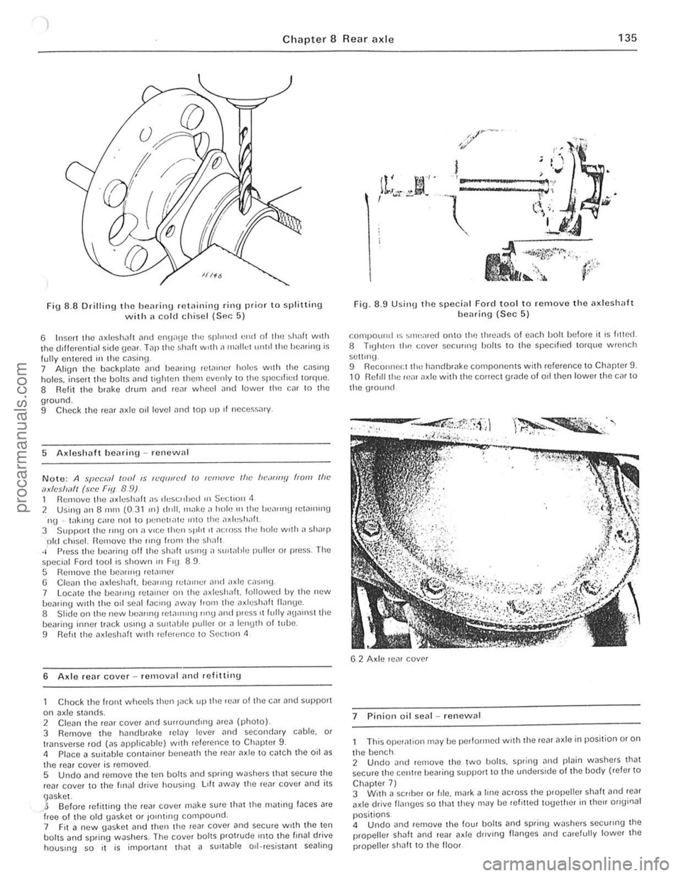
Fig 8 .8 Drilling the beMing rf!t
5 AxlcshiJft homing -renewal
Noto: A SfJL'CI.1f 1001 IS "Hlliller! /0 n'III1:''''''[1 (,0111 lilt' axles/mIl (s,:c Fly 89) 1 Remove the ;,xlushalt as ,h:sG"hcd 1(' St;CIl0n 1 2 Usin\J all 8 mill (0.31 In) dldl, 1Il;,kc a hole III the he,Hlnt! ,etauun\1 119 . t
G Cleiln the l1xlcshnf1. be,non\) ,,,t;WlC' ,Hld "xle C.,1511l\) 7 Locl1le the loe1ll1ll9 HIWlIlel 011 the l1xleshl1lt. followed uy tho new uoa,ing wIth the 001 sel1l [l1CIll\) l1WilY ['om the l1~leshaft Hallge. 8 Slide on the new hea'lIl\) rcta"lIn\) '1119 and pr ess J fully 11\l111l1st tile hearing inner IWck. uSIng a slJItJIJle puller or J ICWlth oftuue. 9 Re fIt Ihe l1xleshalt wllh refe'ence to S ectIon <1
6 Axle reM cover relllov,,1 ilnd refitting
Chock the hont wheels then lilck up the re,l( o f the Cl1r il'l(l SOPPOI1 on axle stands.
2 Cl em1 the reM cover .Jnd surroundIng .Jre" (photo) 3 Remove the hllmlbr"ke relay le ver lind seco nd.Jry cable. or
transverse ,od (as ;;Jpplicilblc) with reletCnce to Ch"pter 9. <1 Place a suitable container helle~th the reM "x Ie to c~tch the oil as the rear cover is removed.
5 Undo and remove t he ten IJOlt s and sprinU washers lhilt securo the reill cover to the llIl,l l drive housillg LIlt aWilY th e re"r cover and its
\Jasko!. ~ Before refitting the ,oar cover Illilke sure thm the mating fJces ilre free of th() old Uaskct or 10nlting compound.
7 FIt a new uasket Jnd then the lea, cover and secure wIth the ten bolts and spring washers. The cover bolts protrude IntO the fillal drive hOUSor1U so it is important that a SUlwble oll·resist.Jr1t scaling
... __ ro*
Fig. 8.9 Usill(J the special Ford tool to removc the axlesllilfl henring (Sec 5)
r;olllpoulid IS SlIll:ilr() d onto lioe Ihro,'ds of each boll bef ore it IS [,twd. 8 TIUhwll tllr: cover secu,,"!.! holls 10 lhe spec,[,ed torque Wfl:IICh
se ttln\)
9 ReCOlillect
Iht! h,lndbr,l~e components with re ference to ChJp ter 9. 10 R efil l ti,e 1e;1I ,ule with the correct 9rJde 01 oil then lower the C,lr to
the UIOUIl(i
G
2 Axle reM cover
7
Pinion oil seal -re"cw,,1
This ope r,ltion may be performed WIth the rear axle in position or on
the benc h
2 Undo ~nd remove the two holts. sprinU Jlld plain washers that secure lhe centre bearing support to the under51(fe of the body (reler to
Chapter 7) 3 With a sc"ber 0' fde. Ill
propeller sha h to ttt() flool I I
J m
procarmanuals.com
Page 144 of 205
) Chapter 9 Braking syste m 143
2
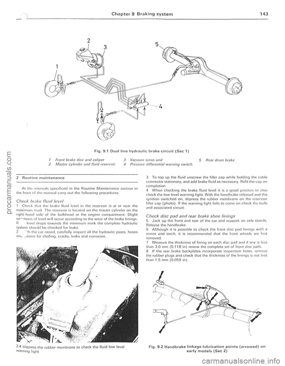
Fig. 9.1 DU
2 ROlltine maintenance
Al III<, u,h!lvals speClficed in the Routine M
2.4 ;-.-
uejJ.es~ the rubue' membrJne to check the fluid low level
Warning IrUht
3 To top up the fluid unscrew the fill er cap whrle holding the c,lhle connector sWtionar y. and add brake lIuid ns necessJr y. R efit the cnp on completion. 4 When checking the brnk e fluid level it is n good practice to also check the low level wnrning light With the hnndbwke rele
Re leuse the hilndb'
Fig. 9.2 Handbr a ke lin k ag e lubrication points (arro\Ncd) on early models (Sec 2)
I .
i
! j..
1:
, ,
procarmanuals.com
Page 145 of 205
144 Chapter 9 Braking systom
9 II there Dre no inspec tion holes, remove the wheels and drums In inspect the linings . 10 Where any lining is less Ih,111 the nllnimufll thickness, renew Ihp. complete SCI 01 re,ll b,~ke shoes. 11 Refi ' the drums lind wheels as necessary then lowe. tho em \0 thl) 9lOund.
Ch eck operation of servo lIoil 12 Visually inspCCllhe vaCUUll1 hose IClIding hom the inlet mlllllfolll Of air box 10 the servo unit fOf dc\c,iOf1l1lon and security. 13 Wit h the engine Slopped. dCI).es s the bra ke pedal several ,imes to dissipate t he VOC U\Ull hoUl the sorvo Imit. 14 Depress the b'i1kc 11Cdll1 wilh moderate pressure then Sin' I the
cnU illC . As the V
R/mew fhe /)rilke I/Ilid 21 lJIucd Ihe hyd.; ."loc sySle m as d"scllherl III Seelloll 15 ilUOwnl! II",
Ihe new h ,,,k\) Ih"d to COnlph: lely 1,lIlhe C:"CUtt he"I!1 bled . 22 AI Ihe sanl\) I"ne rcn,uve Ihe 'Ci" ",ake \I'lOn,s alld check tho wlu,,,1
cylonclers 10' leak"IJe.
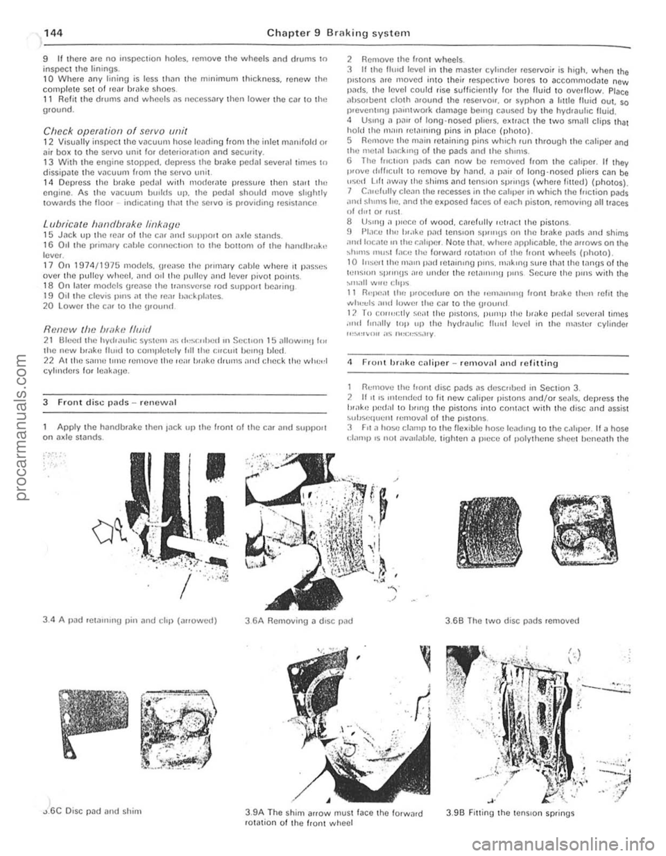
3 Front disc pl1ds - renewal
Apply t
he handbr
I .
. ~ .. " ,) •. :Y.
2 RemOV(l Ihe hont wheels.
3 It Ihe fhnd level in the maste' cylondel reservoir is high. when the pistons l1re moved into thei, respecI,ve bo,es to accommodate new pi1ds. thO leyel could rise sulticienlly fo, Iho fluid 10 oyerflow. Place ilhsoruent clOlh .1round the reSe,yO". o. syphon a Imlo Ituid oul. so 1)'Cven tUlg Pil"ltwOlk
<1 F rollt brake caliper _ rcmoy'll iltld refitting
1 nemove the f,on! disc pads i1S tie sc"lJc(/ in Section 3. 2 1111 'S Itll,,,,d,,(1 10 lit ncw Ci1tiper pistoll s "nd/o, seals. dep,ess the tH.1k'J Iwel,,1 10 hlUlU the pistons i"to COI11i1ct with thO (fisc and
'-.. ~
, .
3 .9B Fitting the tenS ion springs
.--.::.:.:; .
....... . ~,'
灲潣慲浡湵慬献捯m
Page 149 of 205
)8 Chapter 9 Braking system
8
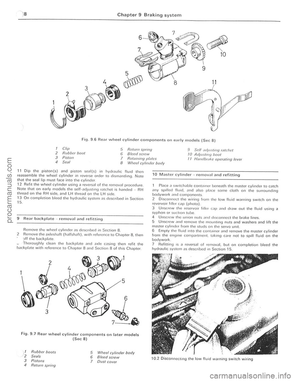
Fig. 9 .6 Rear wheel cylinder component s on "",I y models (Sec 8)
I Cft,} 2 Rubber hoot 3 Pis/oil
5 Relmll SfJflflY 6 Blcell screw 9 Scff ",',uSilll!! wtdll.:/ 10 At/jlls/my boof
4 Seal I Retaming JlI,~tcs II Ullfufb,;,Ac oj/cUlling level 8 Wheel cyhirdcr body
11 Dip the piSlOn(s) and plSlOn SC
9 ROilr backl}lato -rClllovn! (IIHI mfittillg
Remove th ... wheel cylllllier ~s
Fig. 9.7 Re .. r whoel cylinder components on lilter models (Sec 8)
1 Rubber boots 2 Se'lls 3 PiS/OilS 4 Re/vm spring
5 Wheel cylinder body 6 Bleed screw 7 OVSI cover
1 0 MJsle r cylinder -rcmov;11 Jnd refitting
P lace a ~wllcIH'hJe COI11~lIler benem h Ihe mJ$le f cylinde r 10 cmch ,1ny spIlled Ihud ... Mil also place ~on,e cloth on Ihe surrounding hodywork ;lml componems 2 Disco"nect Ihe wirinlJ lrom the low tluid winni,,!) sw,tch on the ,evelvoir 1,lh.1I r:ap (photo).
3 UIlSI:f(lW lill) reservoir 1011111 cap and dr"w out the flui(1 using J syphon or sucl'o" l(,be <1 Unsocw ("u un'on Illl(S IOnd rlist:onncct Ihe b,ake lines. 5 Unscrew lOud r emove (ill) nlolUwng nulS and washers Jnd lilt the mnster cyl",du' hom Ihe Siuds Oil Ih e servo lmll. G Empty llin tlu,d 11010 llie con l,urlcr Jnd remove the master cylinder
from Ihe enU",e comp(lrtmeni. Io1k,ng cllre nOI 10 spill Iluid on the bodywolk. 7 HeliuinU 's II ,eve'slIl of removJI. but on completion bleed the hydraulic syslem IIS (Iescribed In Section 15.
10.2 Disconne cting the low lIuid warning switch wiring
procarmanuals.com
Page 162 of 205
Chapter 10 Suspension and steering 161
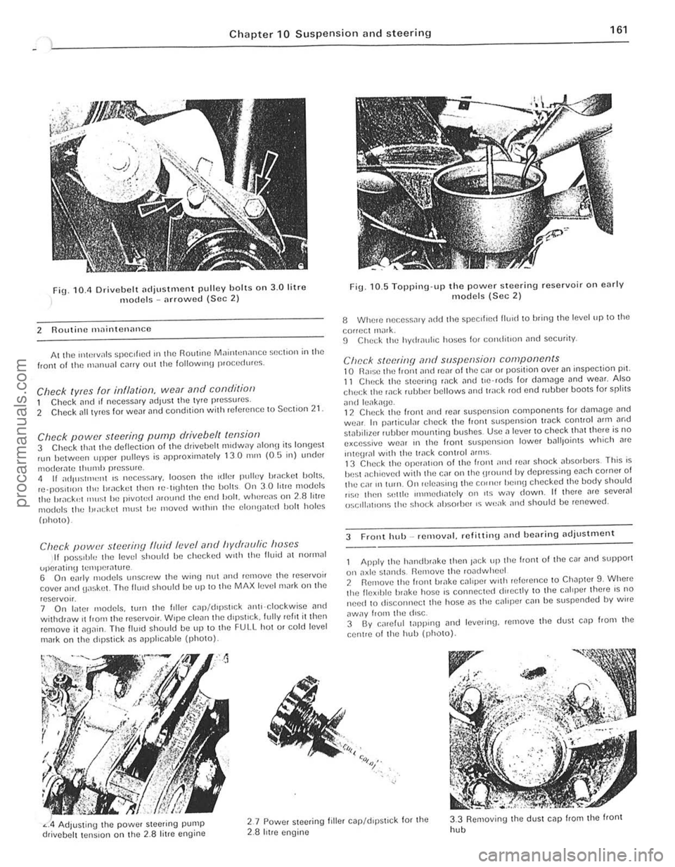
fig. 10.11 Drivebelt [ldjustlllent pulley holts on 3.0 litre models -arrowed (Sec 2)
2 Routine maintenance
At the "*',vals spec ,f,ed III the Routine MainhHlance $()(;t,on in the front of til() manunl c,lIIy out the 101l0wlIl\j p,o(;cdures.
Check lyres for illflalioll, wear and conditioll 1 Check [lnd If necessary adjust the tyre pressures .
2 Check [III t yres for WC[lr and condition with referenc e to Section 21
Check power steering pump drive belt tensiof) 3 Check thm the deflection of the drivebelt m,dway ulon!) its lonyest nlll between upper pulleys is approxirn
(photo).
Clwck puwer steering fluid levef (lnd hydraulic huses II pOSStble the level should be checked w,th the Buid [It nOll1lal
uper,\!mg tClIll)Cr[lture . 6 On c;lrly modcls unscrcw the wing nut nnd relnove Ihe rese,voir cover ilild uaskel. The flu,d should be up 10 Ihe MAX level mark on the
reservo". 7 On later models, wrn tht! hiler C
Fig. 10. 5 Topping·up the power steering reservoir on early models (Sec 2)
8 Whele nec.ess.1'y ~dd Ihe ~pccilled lIU1d to bring Ihe level up to the
correct ,nilrk. 9 ChC(;k the hydr[luhc hoses for comJit,on and security.
Check steerinfj ,-md suspension components 10 n,ll$O tilt) front ilno reM 01 the Cill or position over an inspeclion pn. 11 Check the SleetinlJ wck and t'e 'rods for d[lm3ge und weM. Also check the wek HJbber bellows and track rod end rubber bOOIS for spfilS
ilnd leilk[lge. 12 Chec k the front ,md reilr suspension components lor d"m.Jge [lnd wear. In particuf;lr check the front suspension tr.Jck control Mm ilrod stahiliwr r"bber mounling bushes. Usc a lever to check that there is no excessive we[lr III the Iron I slispenSlon lower IJ[ll lJoints which Me
"'\()\JIill wnh the track conlrol ilflllS . 13 Check the operat,on of the I,ont ;IIHt rear shock absorbers This is
be st ilchievcd with thO} Cilr on the \lfOlind by depressing euch corner of the ca' 1111\I1. On 'ele[lsil\ljthe C()"H~r helllU checked Ihe body should ,,~c thell s"llie IIlIl11ed,mely on ,t~ way down. II there nrc sever.J1 ()sclll;ot'ons the sho(;k absorber IS weilk nnd should be renewed.
3 Front hub _ removal. refitliny and bearing adjustillent
Apply the h[llldhr[lke then Jilek tip the front 01 the cm ilnd support
on axlt! standS Remove til(! rOildwhecl 2 Rernove the front ul;lke CJllper With ,elerence 10 Ch.Jpter 9. Whele the flex,ble br[lke host! is connecte(t dueclly to the cililper ther e IS no need 10 disconnect the hose i1S thO} caliper can be suspcnded by wire
aWily from the diSC. 3 By calelul 1
" :<>,:,~,.
Adjusting the power Sleering pump drivebelt tension on the 2.8 litre engine
2.7 Powcr steeling filler c.Jp/d,pstlck for the 2.8 hIre engine
3.3 Removing the dUSI cap from the front
hob
i
i ,
~ !
procarmanuals.com
Page 172 of 205
Chapter 10 Suspension and steering 171
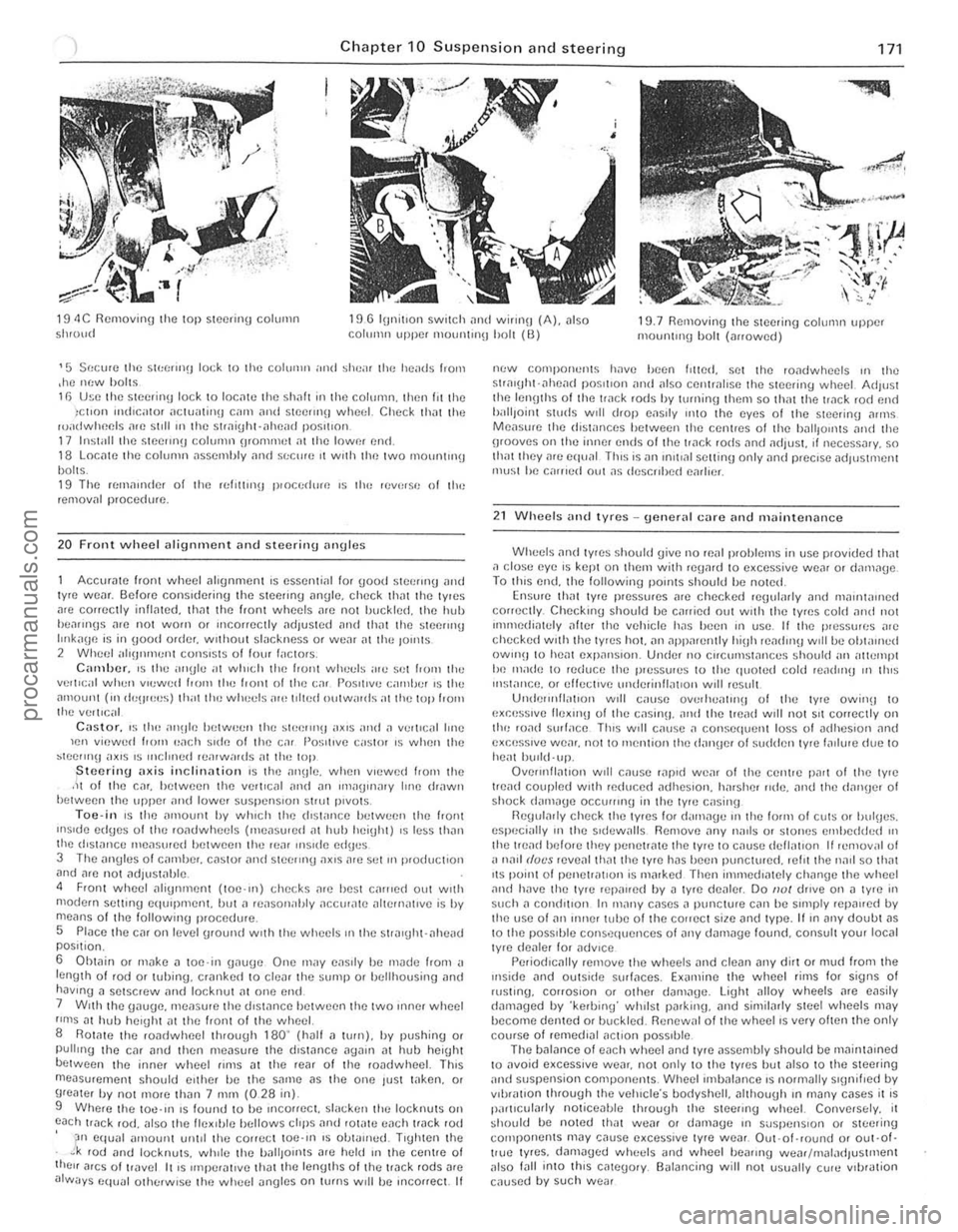
19 4C Removinu the top steering column Shroud 19 G lunitlon SWitch ,1nd wirlllU (A). also COllll'lII upper mOlUllnl!J holt (0) 19.7 Removing the steering column uppcr mounlul(J holt (arrowed)
'5 Secure Ihe SIt:(;(1I1(1 lock 10 Ihe colulIlIl ,lIal ~heil' the h eads I,om ,he m:w holt~ 11) U~e the stecrin\J lock to locate the shaft in Ihe column. then III Ihe )ct,on mdlGltor OICIlJalinn GUll alld Stecrmn wheel. CtlCC~ that Ihe ruadwheels afC st,lIln the 5trai\jht·ahead P05,110l1. 17 Install the Stce!Ul(J column orommet Oil the lowm en(t. 18 LOCille the column assembly ami sr:c",e It wrth the Iwo mOllrlllng bolts. 19 The ((,milliuler of the rellllUI\J proccrl",e ,~ th" reverSI! of lhe removill procedure,
20 F ront wheel alignment and steering ilngles
Accurate front whcel alignment IS essential lor good stoer"'g and lyre WOiJr. Scion) cons,dering the steering angle. check Ihat Ihe tyres
are correctly inflated. tllnt the front wheel s arc nOI IJlJckled. the hub hea"nns arc not worn o r mcorrectly adjusted und thilt the sleflr"'g IlIlkaUfl is in IJood order. wllhout slackness or we,ll at thu Jo,nls
2 WIH;f; 1 "I'!JIununt co"s'st~ 01 loUl I"ctors, C;"lliJcr_ IS the ""Ule "t wilich the front whet:ls ,lie sci from Ihe
verllcal when v'ewud 100'" the IrOnt 01 the c"r 1'0sIt,ve camber 's Ihe .. mount (111 de\J'ee~) th"t til() whucls ,ue toited outwards at the lOp 100'"
thu vert,c;,1
Castor. ,~tho i"'~Jlu between the SIl,erlIlU ,,~,s OIrld.1 v..,'I,e.11 lone len viewud IrOIll p,lch ~,dfl 01 the C,lI 1'0~;llIve castor 's when the ~tcermu ",x,s 'S ",cloned rUiHw,,,ds ill the top jStcerinu ilxis inclin,,{ion 's lhe illl\Jle. when VIewed frOI11 the .It 01 the Cilr. bel ween the verltcal and "n 1Il'''U>I1.1ry hne drawn betwCl)n the upper ilnd lower suspensIon strut p,vots, Toe-i n IS the ilmoUl,t by wh,ch tlte dl5li"'Ce helween the frOrlt
IIlsuJu ed\Je~ 01 the rOildwhecls ('He,lsu1ed m huh heiuht) ,s less thiln lhe d'sWrlCI) ",e
6
Oht"in or m"ke
ne:w components have heen I'lted. set the ro"dwheels ,n the stral\jht·ilheil(f p05otrOn and also cent",lrse the steering wheel. AdJ"st the len\Jths of the track rods hy lllll1ing tltem so th,,! the track rod end IJ,litJoinl studs w,11 drop eils,ly onlO the eyes of the steer inu ilrlllS Measllfe the dislilllces between the centres of the hilllfOllllS illld the grooves on Ihe inner ends of the track rods and ildjust. ,r neceSSilry. so Ihiltthey me equ,ll Thl~ is all lII,t,,,1 sellinlJ only and prec,se ildillstmellt mu~t he carried oul as descrrhed earheL
21 Wheels and lyres -uonNal care and milintenl1nce
Wheels ilild tyre~ shOuld give no reill problems in usc provided thm ,1 close eye IS kept on Ihe", with re\janlto excessive weilr or dilmilge To llns end. the following pOllltS should he noted Ensure thm lyre pressures ",e checked re\Jularly ami ma,ntallled correctly. Checklllg should be c,Hried out woth the tyres cold alld nOI IIlHlledialely alter the vehicle hilS heen "I usc. II the pressures are checked w'th the tyres hOI. iln ap(l,Hently hi\jh readmlJ w,1l be ohw'lled OWlnH to heilt expJnsron. Under n<) Cllcumst
eSpecii\lIy 111 the s,dewalls Remove any na,ls or stones ell\bedded 111 the tread hefore they penetr"te lhe tyre 10 cnuse dcfliltlon If remov,,1 {)i
dilll1i1ged by ·kerbing· wh,lst par king. and simililrly stee l wheels may hecome denIed or buckled, Renewnl of the wheel rs very ohenthe only course of rellled'ill ilct,on poss,ble, The balance 01 each wheel Jnd tyre ilssembly should be mainta,ned to ilvoid excess,ve weilr, not only 10 the tyres but illso to the s teering and suspension components. Wheel imbillilnce 's normilily S'\ln, f,ed by v,i)rilllOn through the veillcle·s bodyshell. illthouUh III many c~ses it IS piullcularly nOliceahle Ihrouoh the steenng whuel. Conversely. it ~hould bc noted thilt weilr o r dilnlaUc 111 suspellS IOll or steer ing components may '.:ause e~ceSSlve tyre wear. Out·of·round or out-of· t!Ue lyres, damaged wheels and wheel !leafing weilf/ nlilladJustntent also lilll into th
,.
:.
procarmanuals.com