ABS FORD CAPRI 1974 Workshop Manual
[x] Cancel search | Manufacturer: FORD, Model Year: 1974, Model line: CAPRI, Model: FORD CAPRI 1974Pages: 205, PDF Size: 43.75 MB
Page 8 of 205
![FORD CAPRI 1974 Workshop Manual Jacking and towing
Jilckillg poillls To chan!IC ,I WhUt:1 111 ,11 ,-,"W!ICIICY. usc the t:]ck slIpplled wilh the velIe!!.!. Ensurf! 1hal the Hhldwh,:cl nuIS;OH! ,ciC;lSCd Imlole Ii, cklll\j up thO FORD CAPRI 1974 Workshop Manual Jacking and towing
Jilckillg poillls To chan!IC ,I WhUt:1 111 ,11 ,-,"W!ICIICY. usc the t:]ck slIpplled wilh the velIe!!.!. Ensurf! 1hal the Hhldwh,:cl nuIS;OH! ,ciC;lSCd Imlole Ii, cklll\j up thO](/img/11/56932/w960_56932-7.png)
Jacking and towing
Jilckillg poillls To chan!IC ,I WhUt:1 111 ,11 ,-,"W'!ICIICY. usc the t:]ck slIpplled wilh the ve'lIe!!.!. Ensurf! 1hal the Hhldwh,:cl nuIS;OH! ,ciC;lSCd Imlole Ii, cklll\j up thO ca. and make SlUe Ih;u the .lOIn of the 1,1Ck IS luU.,. cnua\Jcd wI,h the body bracket and thatlhe hase allhe Jilek IS st;lIldlt '!J on a 111111 surface. The Jilek supplied w!lh lhe vehIcle IS 1101 $",,;,l)le lor lISC when laislflg the ve!.iclc lor U\;J",l()II;IIlCC or 'Cp,1If up,:r;J110ns. For this walk, use a trol ley. hyd'ilui,c Of screw-Iype tad IOCille(1 und!:. thO f,OIll crOSSlllcmbcr. bodylrame s,(ic-mcmbcls 01 ,ea, il~le cnsing, .1$ ,UuSlr
Fronl IOwin9 pain I S (ll • • owed )
Towing poillls II you/ vehIcle ,s bCIIl9 IOWl;d, m,lke SUfe lhal the lOw rope IS auached to Iho 110111 cmssmembcr or, where Ilued. the towlog eye auachcd 10 Iho 11001 ClOssmember II Ihe vehicle IS equipped wilh atilOma llC Iraosrlllsslon, the d.slanCe lowed rnuSI nOI exceed 15 miles (24 km). 00' Ihe speed 30 mph (48 km/h), olhe.wise sefious damage 10 Ihe Ir
10Wlflg eye.
, 'I I -J ' ,;
~)
'J
: .. ': .... 111"'"' ..... _-.___ •• _...:. __ ... ,
Jacking l)oinl S
Rear towing I)oio \s (arrowe d )
procarmanuals.com
Page 98 of 205
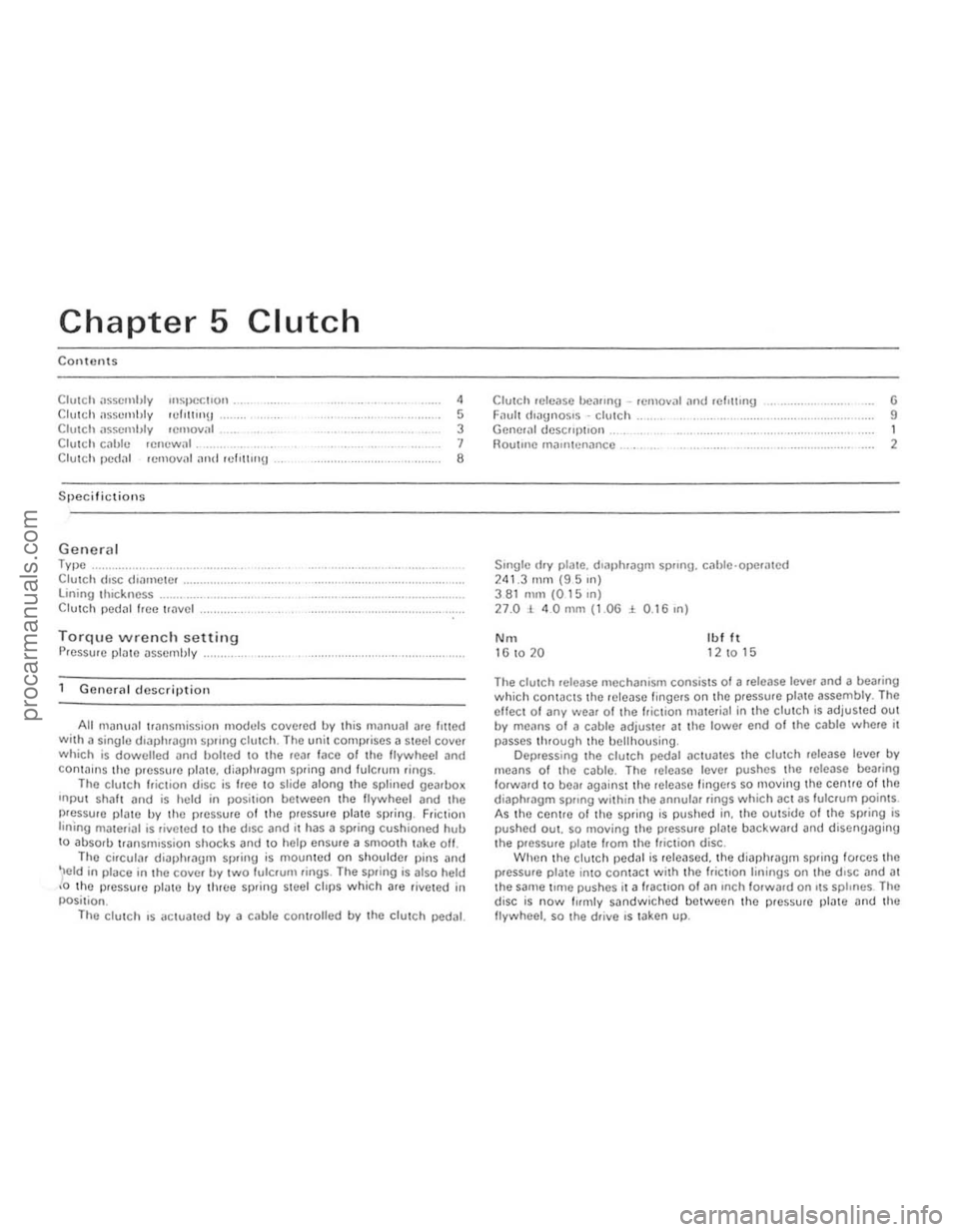
Chapter 5
Contents
CIUICh il$scmhty '"SIJoCcl'Qn . Clu\(;11 assembly 'Urn!!ll!) Clutch llsscmhly lemOY," C lutc h cilhle .efluwal._
Clutch
Clutch !Jedal rClllovnl illld ,cflltl"U
Specifictions
Genera l Type ..... Clutch (lise (hamClcr lining tlnckncss Clutch pedal hcc "
Gene.al description
,
5 3 1 8
All manu:!1 transmission madllis covered by this manual nrc lilted Wilh a singlo dl3phrilgll SpllJlg clutch. The unit COlllt)riscs il steel cover which is dowelled and bolted to the tear lace of the lIywheci ilnd conla i.lS the pressure plnte. diaphragm spring and fulCrum .ings . The clutc h " iClio n disc is
ee to slice along the splineJ gearllox
Inpu t Shillt and is held in posi t,on between the flywheel and the pressure plate by the pressure of the pressure plate spring , Friction linIng materiill is riveled 10 the d,sc and II has a spring cushioned hull to absorb transmission shocks and to help ensure a smoo th take oft. The circular diaphrilUm spring is mounted on shoulder pins ilnd
'Ield in place in the cover b.,. two fulcrum rings . The spring is also held ,0 th e pressure platc by three spling steel clips which are rive ted in
posi tion .
The
clu tC h ,s aCluated b.,. a cable controlled b.,. the clulCh pedal.
Clutch '0Ie,150 bCilfl"U -remova' and wl,u,"g Filult (ioilU"OS'S -clutch Generill descllptlon . noutlilc rn,untenanco .
SlIlgle (Iry plate. dlill)hragm sprong. cilhle ·ope.ated 241,3 rnm (95 Ill) 381 nun (0 15 In) 27.01 40mm (1.OG:i 0 .16,n)
No. Ib l It 16 to 20 12 10 15
G 9 1 2
The clutch release mechanism consists 01 a .elease leve. and a bearing which conwcts the lelease Imgers on the pressure plilte assembl.,.. The eHect of an.,. wear of the friction ma terial in the clutch is adjuSled out b.,. means 01 a cable adjuster at the lowel end 01 the cable where it
passes through the bell housing .
Dep.ess lng the clutch pedal actuates the clutch release leve. b.,. means of the cable . The lelease level pushes the lelease bearing
forward to bear against thO release l ingels so moving the centre of the diaphf()gm sprong within the annular rings which act as fulcrum points.
A s th e centrO of thO spring is pushed in. the outside of the Spling is pushed OUI. so Illoving Ihe pressure plme backward and disengaging the p.essu.e plate flom the /tielion disc . When the Clutch pedJI is Icleased. the diaptllaglll spring torces the plessule plate into contac t w ith the frictIon linings on the d,sc and at the saIne t,me pushes it a flactlon 01 an InCh fOlward on I\S splines . The
disc is now fuml.,. sandwic h ed between the plcsswe plnte Dnd the
flywheel. so the d.ive IS laken up.
procarmanuals.com
Page 101 of 205
"00 Chapter 5 Clutch
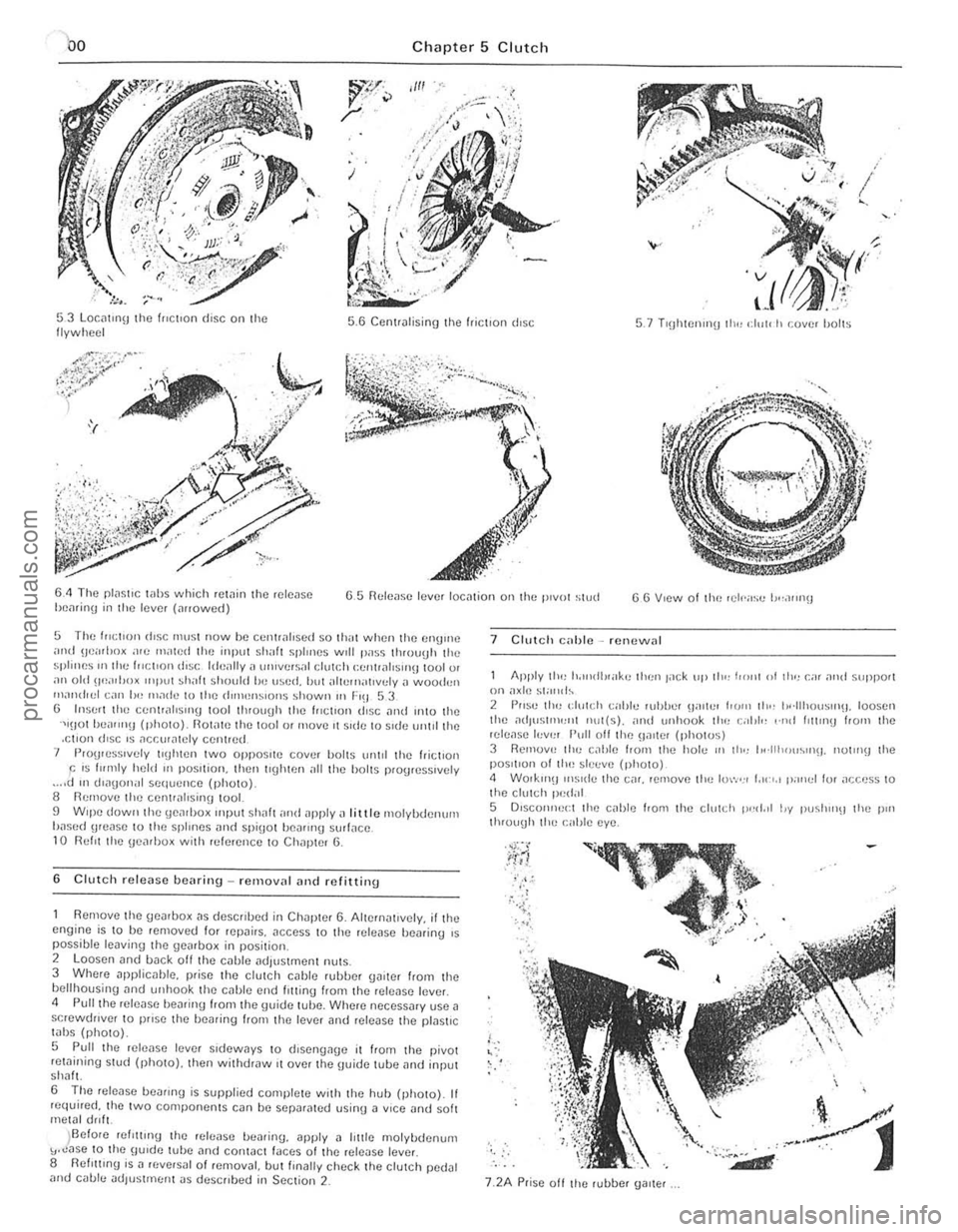
53 Locmlll\J the (flCllon disc on the
f lywheel 5 .6 Cent,.,l ising the friction disc 5.7 TI\)htIJnlll!) 111" ,: 1,,[, h cover holls
6.4 The plilSllC wlls which .cWin the fclcJSC hcnrinl] in the lever (""owed) G 5 nt:lcas(l levor IOC,11;01) 011 the 1"1101 stud
5 The f"~lI()n rt.!;c must now be Cclltrilloscd SO Ihill when the (IllUme imd !Jci"loo~ .1<0 milled Ihe input shall splmes Will pass 1I110uUll the splines III Ihe )HCIIO!) diSC Id(!,lIly a wlille.s;,' dUh;h (;C!l!r
Remove thc gcarbox "s dcscflbed in Chaptcr 6. Alternal,vely. illhe cngi ne is to bc removed for repairs. acccss 10 the rclcilse bcminy ,s possible leaving lhe gearbox in position. 2 loosen and back oil the cable adjustmcnl milS. 3 Whcre npplicable. plisc lhe ciulCh cnble fuhhel gaitcr flOm the bell housing nnd unhook thc cahle end lotting from the release fevel. <1 Puilihe release I)ealing hom the \Juide tube. Whcre necessary use a scrcwdrlver to pflse the f)Caring flom the Icvcr and lelease the pfas\lC
tabs (photo).
5 Pull t he rclease IiNCI sldcways to d,sengage it from t he pivot retaining stud (photo). thcn withdraw ,t ovcr thc IJuide tube ,1nd input shah
6 The rele ase beann\) is supplied completc w ith lhe huh (photo). If fC(luired. thc two componenlS can be scparated usinU a VICC and soh metal drill.
)Before relltllng (hc releasc bcariny. apply a lillie molybdcnum "."ase 10 the \llude tubc and contact laces of the release lever 8 flefl!1lng is a ((,versal of remov~l. butllnally chcck the clutch pedal and cable ndlUsllllenl JS descflbed in Seclion 2_
7 Clutch c;lllic -Icnewnl
Apply tlol) Io.",dl!<"k" llien lilCk "I' lilt: j'onl of 11"1 Gil o1l1d suppor( on ax il! ~!and~ 2 PIIS" th" dUlch callie whlJel (jilll'" horn lh" h'·lIhou~u'(j. lousel! the ati,US111l'JllI nul(s). ;IIHI unhook the c;,I,I" ,·nrl IlIllllB hOIll lhe release h,v,,, Pull off the !Jalter (phOlUS) 3 Ikmuv" ti,,) c,lhle frorn lhe hole II) lh., 1,,·lIh"u~"l\J. nUlo)\) lhe posltlun of lhe slccve (phOIO) <1 WOlkln\l illS Ide (hC Cilf. remove the luw,,, I,,,",,, pallel lor
j'., ;. . , , , .;{
'-,
7.2A Prisc all the rubber Ualtef
.. ~
d
procarmanuals.com
Page 107 of 205
·06 Chapter 6 Manual gearbox and automatic transmiss io n
disengilge the gearbox inpu t Shill! hom ,ho clutch p,Iot bearing ,111(1 clu tc h friction disc. I, is imporlanllhal,hc engine and transmi ssion <'lre kept in lino while this is being done. 14 When the gearbox shaft is cleDr of the clutch, remove th e
tran smissio n assembly from bCn(!illh the car.
15 When refiuing, ensure 1il1 the clut ch pilot h earing in the end althe tfilnksha h is ill plilce Jncl is scrviceDble. Tic the clutch lever 10 the clutch housing, 1 0 pr(!venllhe release le.rertrolll slipping out while the ,Wnsmission assembly is being lined. 16 Smear some molybdenum-based grease OntO the end and splines 0' the gearbox input s!mh lind refit the gearbox by reversing the fcmovili p.ocedure. 17 II is impO.IMll when offering up the {jOMOO)(. th,lt il is e~
slightly until the splines enter Do not iluempltO lo.ce the tfilllsmisslOn
ontO thO enlJlnO ThiS Illay (i
'8 Ahe •• el,uinn has been completed. chuck the 011 level Ifl t he .r
Romoye the lou. bolts hom the 1011 cove. 01 the t.ansm.sslon c~t()"sion housin!J ilnd f.om the lri"'snHs~ir)Ol eo'S<' Ilcmovflthc \:oye. s.
t.1king c
R emoYo the .eyerse idle , shah by sc.ewing a suitable bolt into Ihe end of Iho shah and then leye.ing the Sh;'lit Out uSing Iw o open ·ended spanne.s. Fi\)
.
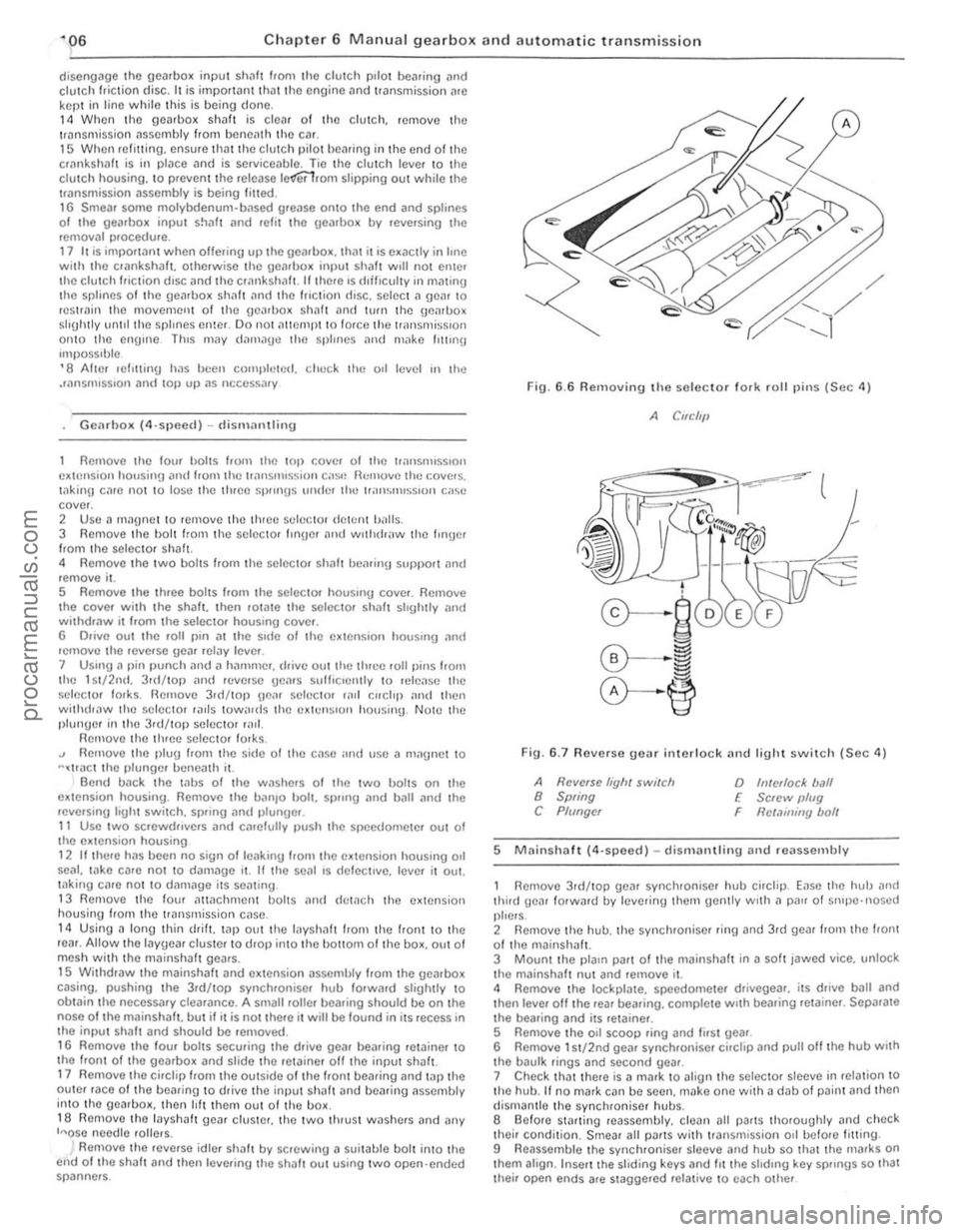
6.6 Removing the seleclor 10lk rolillins (Sec 4)
A CIfC/'11
Fin. 6 .7 Revorso gear interlock nnd light swil c h (Sec 11)
A Ravelse liyh, switch 8 Swing C Plf/ngcr
o h!/ellocl< ball E Sc,ew IJlug
Rct.1ininy bolt F
5 M
thud gear lotwald lly lel/erinu the,n gently wrth a p
their condition. Smear all Pi/ItS wilh tr3nsmission 011 befo.e fitting .
9 Reassemble the synchroniser sleeve and hub so that the nlafks on thorn align . Inse.t the sliding keys and 1IIIhe shdrn\) key sp"ngs so Ihat Ihei. open ends afe stagge.ed re lat ive 10 each other
procarmanuals.com
Page 111 of 205
~10 Chap ter 6 Manual gearbo)( an d automatic transm iss io n
operlltlon. looseness between the inner ;mel oulC. ';)ces. imd 10f genera' wear. NOfIll.llly they should be .enewed on a gearbox lh<11 IS being .ebuil l. 8 II Clther 0' the synchrOnise. unllS ;nc WOUl II w Ill be ncccssmy 10 buy" complete assembly as the Pill ts ,lIC not sold individually. Also check the sliding keys 10' we;'!. 9 Examine tho ends 0' IhO scl(!C I(ll' lor ks where they rub "g.1In51 the channels in the peJiphery of the synchrOntSfl f units_If I)()Ss,ble cOIllp.."e the sclecw. lorks with new Units to hell) dC1Crminc the weill lh,,1 h,IS occtJUcd Renew thelll " worn. 10 If the bCilring bUSh ,n Ihe CXI(mSlon is b;uliy worn II,s OOS110 [
When any hOlt screws "110 a throuUh hor". JOllll11\!J COlllpnulI/t Should hc nj)lllted to I he lhwads 011l11! holl helorc It ," InS/"h~1 2 Fit Ihe /cve.so Idle. He"r WIlli Ihc It,oolle on the !le;1I tuw;IId,. Ih,' lenr.lnsel! Ihe .dle, s h ah nnll dlllle 11111 with .1 pla~t.c·IIIl:IIIt].1 h;""""" unllllhc OOltOnl ollhe Slel) on the end ollhe shalt.s IIIIsh WIth lhl! ,,11.1 0 1 the gCJloox. Thc mIlled "
FlU. 6 13 Apply 101ll1lng compoullll to the threilds 0 1 Ihe bolts. lIl~e
0,1
the new IIlput sh,ll! ncedle rollel heilrlllg ilnd push I t 11)10 tllC oJorc 01 the input sha ft Slide the lOP gC(lr synchroniser baulk IInu on to the cone olthe IIlJ)u I sha h 8 FIt the extension houSll19 gnske!. lhen InSerl the ,1s~",hlcd mainsha/t into Ihe rca. 01 the box anll (frille II III untIl the nose 01 Ihe Illalnsh~h is fully engaucd in I he II1PUI shilh necdle l>c,l11nU 9 Carefully lu.n the ge;ubox upSIde down. so thilt the layshalt \}e,lr elusler dIOI)S mto engJgelllenl with the malnshillt Jnd IIlpIII shalt Check thilt the gear and the two lluust wilshe.s il.e III line and then c,l.elully push in the layshalt from thc leal. If necessary till) Ihe S h ,ll! In with the p lasuc·headed IHI/llmer. bllt take grC;lI CJre not to dlslodUe Ihe thruSI washels or needle .olle.s . When fully home. the h Ollom of Ihe slep on the .dlel shalt shOuld be In hnc with Ihe face 01 the box and Ihe mIlled flats should be in IIno wllh the Idler shalt oo.e. 10 Turn the geilrbo~ the lighl w;ly UI) Jnd align the hole in the 1>.111 bemll1g SUpj)Orl WIth the dowcl on Ihc cxtcnsion housing. Fit the eXlenSlon housing. Apply jOlllllnu coml)ound to the ttlle<1ds of Ihe bolts. InSClt them and tightcn 10 thO torQuc wrench seHlng gillen In the SpeCll l
C3tions . 11 1/ a new cxtension bush has been fllle(1. check Ih~t the notch 01 011 groolle III II ilhgns wllh lhe o ll,elurn grOOlle In thoJ extension housing. If thc now exlension housinU 011 senl hilS not illready been filled. slide It Ollel the extension Shill t and enrelully tap it in wilh n h~nllller and n
b lock 01 wood.
1 2 FIt J ncw O ·ring to the spcedomeler pll110n assembly. relit the ~Sembly and f it the C llcli l) to socure i1. ,3 Inser t the r(,lIerse gear interlock plungel. ball and spring. Fllihe boll with aloek plate and lIl$crl tI,c l.Iol t. TIghten the boll and bend Ihe lock plilles to seCure ,to
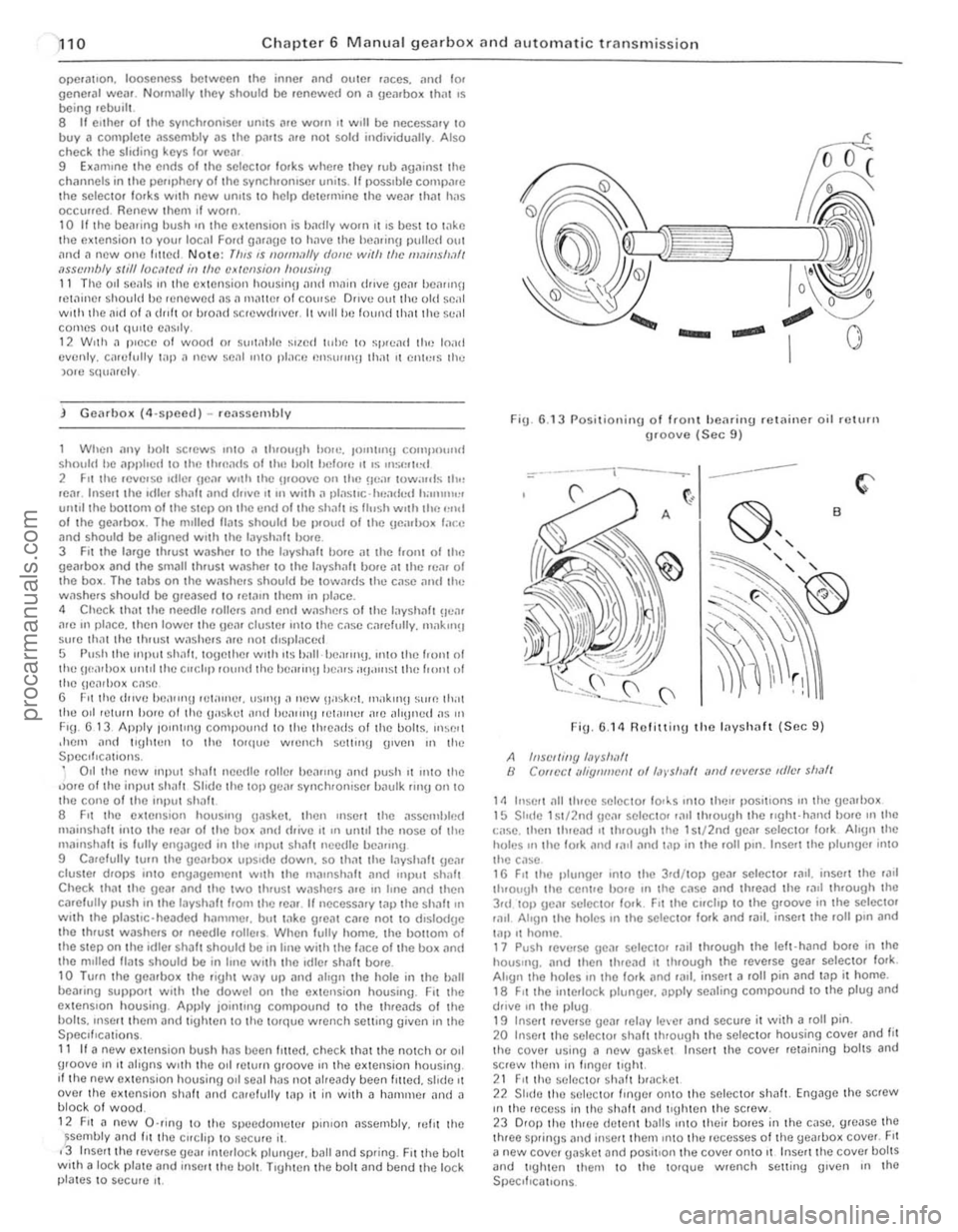
Fig. 6.1 3 Posilionin g of Iront hearin\} .e lainer oil return \}Ioove (Sec 9)
=-*.------t---.---- ---
FiU . 6.14 R olitting the Inyshaft (Sec 9 )
A hlSC//ing /,1vs/!I!f/ B ClJflec / lIi1:qlll!!efl/ of /,J)'$/I,III illld 'fJve.se IdlfJf sl!,lfl
1/1 Insert ~II Ihrce selecto, 10l~s Into Ihcn I)ositlons 111 lhe gearl)o~ 15 Shllc 1~1/2n(1 \le,1r selector ,,111 through Ihe r,ghl-hilll(1 bo.e mille
I:ilse. Ihell tluead ,t through the 1 S I/2nd gCM selector lo.k Align Ihe holes 111 tile lo.k and r~11 ,111(/ t<1l) in the 101l1)ln. Insert the plunUe/ into thc c,lse 16 FIt Ihe pltlllgc/ '1110 Iho 3rd /lOI) ge,ll selecto. lad. inscrt lhe 'illl
t h .ough Ihe ccnHe hore III the C,lse ;lnd Ihread the raIl Ihrough Ihe 3rd 101) gea. sel()(: tor lo.k. Fit the clfchp to Ihe groolle ;n the se lecta' lilll Ahon Ihe holcS III the selectol 100k and ,;lil. insert the loll pIn and lal) .t home. 17 PUSh lellerSC gc,'1 seleelo, r;llt Ih/ough Ihe lelt·hand bore in the hou$"'g. and then thread 11 through the rellerse gear seleclol fork. Align Ihe holes III Iho IOrk and 101.1. inserl a roll pin and tap it home. 18 FIt Ihe interlock plungC/< apply sealing compound to the plug and dfille In Ihe plug 19 Inse!! ICllerSe ueJI ,clay lever and secu/c it wilh a roll pin. 20 Inse't thO sCleCtOr shalt ItHough the selcctol housing COllel and fit the co~er using a new gaskel Insert the COlier rewining bolts and screw them in Iingel lIghl. 21 FII the sel/lCIO' sh:lh b'lIcket 22 Shdo lhe S(lIOClOr flnge. onto the selec tol shalt. Eng~gc the strew III the ,ece~~ in th O shaft ~nd tIghten the sc rew. 23 0101) lhe Ihloo dctent ba lls 1I1tO thcir bores in t he casc. g1Case the thleo sprinus alld Ilise rt thcm Into the recesses 01 tile yeJ.1>ox COllel. FII
a new COlier gasket and positIon Ihe COllcr onto II Insert the COllel holtS and tlghtcn Ihem to tho 10Ique wrench suiting (Jillen III lhO SpeClf,callons
procarmanuals.com
Page 131 of 205
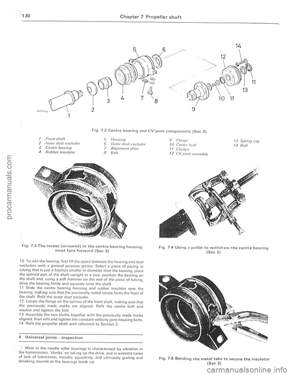
130 Chapte r 7 Pro pelle r sh aft
14
. 12 ~
"> ., I>
" 10 11
9 a
·6)6f
. -r 3
~I"")~ 2
Fig. 7 .2 CCllIre bearing and CV joint cOIll I)onenls (Sec 3)
1 FIO,,/ sll,1// 2 Inncr (/(IS/ cJ(cfudm 3 Cemrc bC.1riny 11 Rubber in$u/.l/(J'
5 1f00wl/f/ 6 Du/!)( rlusl cXl;/mh'I 7 AIlYflml'lJ/ shim 8 flull
FiU · 7.3 T ho recess (;ufo\l\lcd) in the <:orllre bearing housing m ust la ce forw(.rd (Soc J)
10 To lI~fll the bearing. first f,lI the 51)
alrgned. Ihen refit and tighten the constanillclocity joint housing bolts. 14 Refit the propeUef shalt With ,efefcnce to Section 2.
4 U nillorsal joints in sp ectio n
) Weaf in the
needle rollef heafings is Ch,Uoclefi sed by vibfalion in the tfan srnission. 'clonks' on takrng up the drille. and in e~treme cases 01 tack 0 1 lubficat ion. mOlalhc squoaking. and ultimately grating and
shrie king sounds as the bOilflngs breiJk up.
9 Fl.",!!.: /0 C('/IIf<.' 1",11 /1 Cllcllf'S 12 CV /01111 ilssl:mbly
13 Sprillg c.lf' 14 Boll
Fig. 7.4 Using.~ plillor 10 withdraw the centre bClI ring (Sec 3)
Fig. 7.5 Bendi" g the metal tabs to secure the insulator (Sec 3)
procarmanuals.com
Page 134 of 205
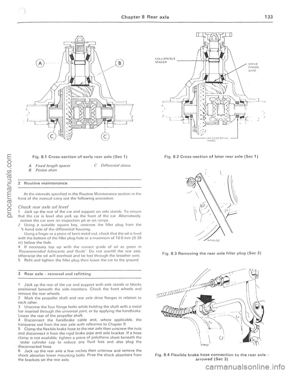
1 Chapter 8 Rear axle 133
Fig. 8 .1 CrOSS-Sl!ction o f cnrlv rCilr ;1xlo (Sec 1)
A Fixed /ellglh SIJ.1C(!f B Pinion slum
2 Routino mnintcnoncc
C Dd1clCII1.11 S/II"'$
At lhe uHerv"ls specIfIed 111 the HOlltmc M.111l1cn;mc c SCCllon III the 110111 0 1 the mnnu;1I c""y oul the following p,uccdw(!.
Check fcar axle oil level 1 Jilek lIlllhc IvaI of the Cil! ;uHf suPPOtl on axle ~I"nds T o C!lSI'''') li1,'l Ihe Cilr is lellel ;,150 I
3 R e
posi tioned lIancnlh the sid(Hllemhe.s . Cho ck thc tronl wheels and rcmove the .ear wheelS . 2 Mark thc p.ol>elle. sh;J1! ilnd .eil'
t'ansverse ,od from the .ea. (Ide wl,h refalCnce 10 Chal >!el 9
5 CI
COUAPS'8ll -----i--i!~e"'.!i SPACH'
,
Fig. 6 .2 Cross·sc ction of I"ter rear Ilxle (See 1)
Fig. 6.3 Removing the rear ax le fillo r 1)lug (Sec 2)
Fig. 8.4 Flexible brake hose connection to the .ear axlearrowed (Sec 3 )
procarmanuals.com
Page 147 of 205
Chapter 9 Braking system
4 Note that in order to m,lintOIll even braking both discs should he renewed ill the sal1 1 e lime
5 T o remove il dl~c. first remove the tHlb as described in Chllpter 10 . 6 Prise lip th(J locklllU I"hs. unscrew the fOlll bolts. and remove the disc from Ihe huh.
7 Clcilll the Illllirnu !ilces of the disc and hub then locale the diSC on the huh and allgel the holt holes.
8 InScrt new holt~. tOI){)ther w rth new locking plates. and tiuhten them to the specrfre(1 torque_ loc k b y bending the tabs. 9 Th e huh Illily now he ref Illed with reference to Chapter 10.
7 ReM hrake shoes -rt)rlewal
Check the front wheels th!:n lilck up the rem of the CM lind support on ,1~le stands. Rel(,a5e Ihe handbr,lke lind femove the reM roadwh~~els
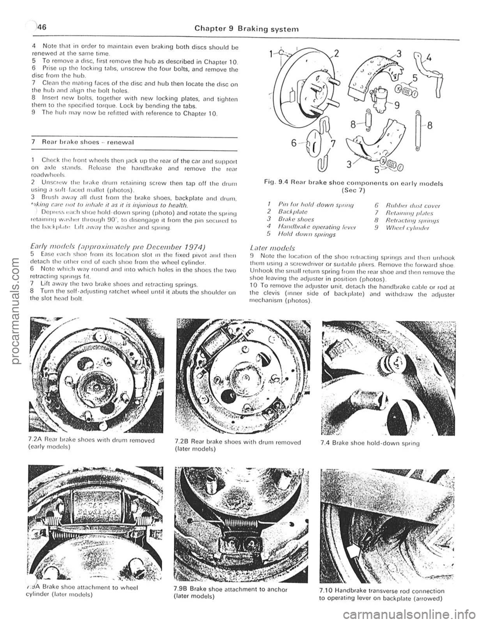
2 Unsr",w th" I"ake drum lewinrnu scrow then t.1p off the ,IIurn \Jsing ;I ~"It f.lced milliet (photos) 3 Barsh away all dust I.orll the brilke shoos, backplate ilnd drum, ",killfl can' ""I /0 11111""., II ;I S 1/ is iHjmiaus to "e,11Ih Del""~~ ,,;och shoe hold-down sprrng (photo) ,lnt! rOt,lte the sprrn!! ",w"nIlH w.r~I"" th,ou!lh 90" , to rhsengage ,t from the pm sel:rr",d 10 Ihe had' pt. 'I" 1.,11 ,"wily 1Ill! w;'shel and spm}!J
Early moth'ls (iippmxilllawly pm Df!c()tllbcf 1974) 5 Eas,) .. ad} shoe loom ,t~ loc;rllol1 slor III the lixed pivot nrrd tllen detach th,-othe! '~nd 01 ea(.11 shoe f,om the wheel cylind'lr, 6 Note whld, W.1Y fOwul and IIltO which holus in the s hoes tlH~ two retracting sP""Hs Ill. 7 lift ,lway t ho two brake shoes "nd retracting springs. 8 TUf(lthe self- ad lust'ng ratchot wheetum,1 it alJuts the shoulder on t he s lot head bolt.
FiO_ 9.4 Renr brake shoo components Oil e,lrly moclnfs (Sec 7 )
I Pili 'm froft! dowII sWIIIII 2 Buc/."liTlt! J B',l~'l! shot's <1 II,-IIIrflHiiAe opcra/jllY h-v", 5 lIo/d d"wII slNil/ys
Lawf lII oduls
6 fir"",,:, (/",,1 r:lJvlH 7 IId;III1I1'!IIII.llr!S 8 flNr;Il:IIl'!! .,'I,"IIIIS 9 WI",,:II:yllJldl!l
fJ N Ole the local,on of the shoe 1"lpacl,no sprrll!ls nrld thell unllook tlwm \lSUl!l a s(;lewrh,vef or SUil;!tJle plo~"s. Remuv,) th" lorw,lrd shoe Unhuok tho small pelurn spring loom the reill shoe and then rumuve the shoe lenvinlJ the adJus!Cr in pos,tiol} (ph o tos)_ 10 Tu remove tim adjuster unit. del
,
j
procarmanuals.com
Page 158 of 205
rhapter 10 Suspension and steering
F
Front suspension
Rear suspension
, . , enflg gear (manual) Type ................... ....................•................ Steeling whecl turns (lock to lock) .. . LUbrican t type ............. ................. ...... . lUbricant capacity _ ............................. .
" G 3 ,
7 ,
• 20 1 15
"
Powel stCCIlIlg Ilump .. remOllal ,111(1 fcllting RCiU leill SI)II119 . emoval. bush renewal .1nd Iclottlng Flo;"), shock iJbSOfOO' removal ,m(/ felUtlng , ............... , Rein sl
Steering column -rCmov
Steeling wheel -rCfllov
Wlleels nlld lyres -uencrill CilfC and maintenance ...................... .
17 10 9
" 2 19 13 12 ,.
" 21
Independent. MacPherson strutS with Integral telescopic shock
ab sorbers
Rack and
pinion 3.36 SAE 90 EP gea r oil 0.15 IlIre (026 pint)
i
i.
!
I (
!
:~
I:
II
procarmanuals.com
Page 159 of 205
)8 Chapter 10 Suspension and steering
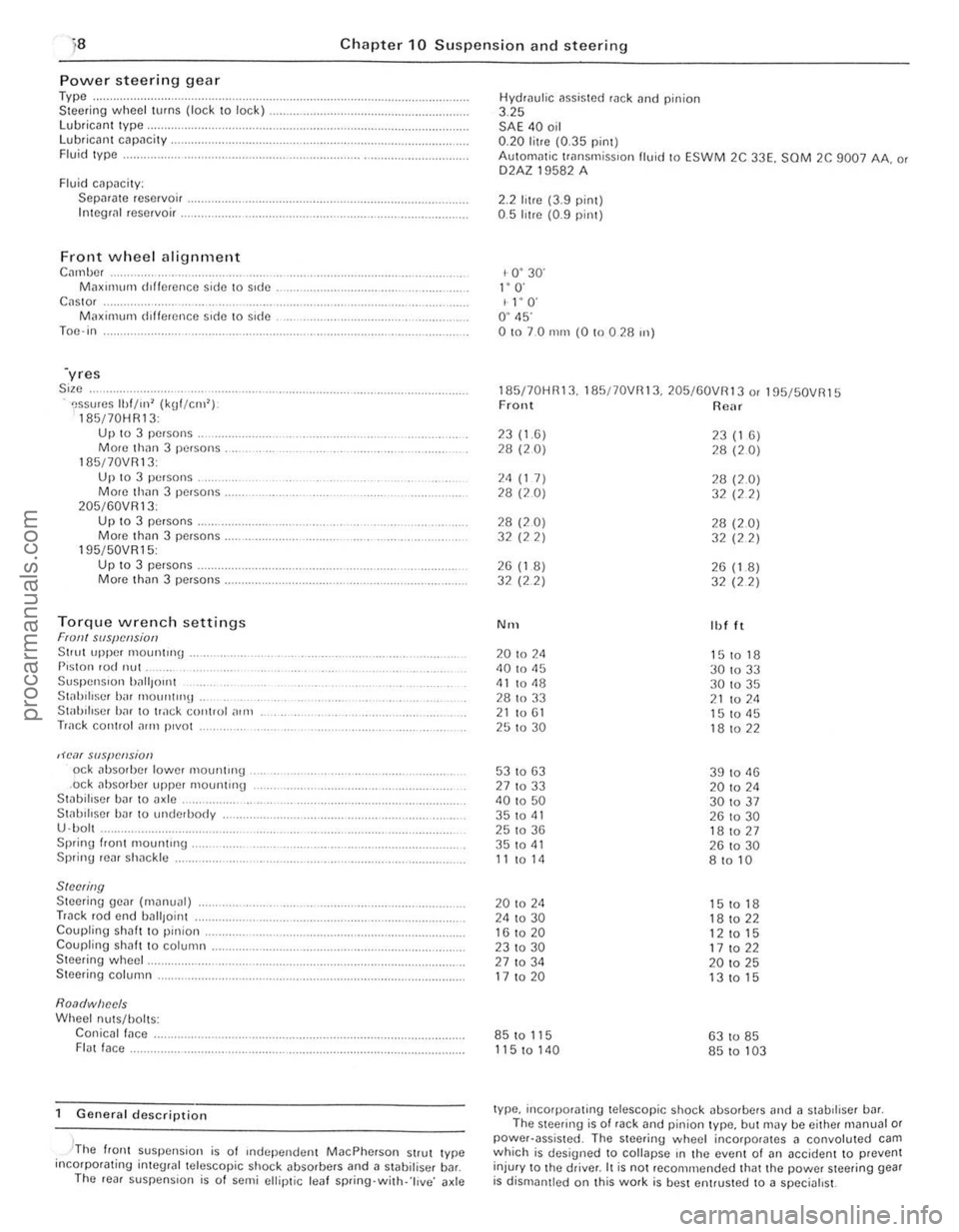
Power steerin g gear Type .. Steer ing wheel turns (lock to lock) lubrican t Iype, Lubricant capacity . Fluid Iype .
Fluid cilpacily: Sepilrilte reservoir . Integli!1 reservoir .
Front wheel alignment C",nbc, M;lXll11um dlffcrence side \0 side C
195/50VR15: Up 10 3 pe.sons . Morc th(ln 3 persons.
Torque wrench settings Fran! SIIS{!cl!siotJ Stlut upper 1110untrng . P,ston rod nut Suspen Sion ')~",{Jont St;rhiliscr birr mount"'lt . Stab iliser h;rr to track control ,)In,
Track cOIHlol ~rrn p,vot
,H'o1( slIspCIlsion od abso,bcr lower mountH'g .ock absorber upper mounting Stabillser bar to axle .. St;rl.lIlIscr har 10 underbody
U ·bol . Sprinu I.ont mount"'g . Spring rear sh;rckle
SINNing Steering gear (m~nual) Track rod end uall,oint Coupling shaft to pinion. Coupling shah t o column . Steering wheel.
Steering column.
Roa(/wiJec/s Wheel nuts/holts: Conicall;rce . FI(lt face.
General description
, -'The flonl suspension is of Independen t MacPherson Strut Iype incorpotating inleglal telescopic shock ~bsorbers and a stabilisel b~r. The ,eal suspens ion is o f semi ellip tic leaf spring·with· 'l ive ' axle Hydrau
l
ic assisted rack tlnd pinion 3.25 SAE 40 oil 0.20 litre (0.35 pint) AulOm
1- 0 ' 30' I" O· I l' O' O ' 45' 01070 nun (0 !O 0 28 ",)
185170HR13. 185/70VRI3. 205/60VR13 o. 195f50VR15 Front Rear
23(1.6) 23 (1 6) 28 (20) 28 (20)
2<1 (1 7) 28 (2.0) 28 (20) 32 (22)
28 (20) 28 (2.0) 32 (22) 32 (22)
26 (1 8) 26 (1.8) 32 (2 2)
32 (22)
N'H Ibl It
20 to 2<1 151018 40 to 45
30 to 33 <11 to <18 30 to 35
28 to 33 21 to 211 21 to 61 15 to <15 25 to 30 18 to 22
53 to 63 39 to 11 13 27 to 33 20 to 2<1 40 to 50 301037 35 to 41 26 to 30 25 to 36 181027 35 to <11 26 to 30 11 to 14 8 to 10
20 to 24 15 to 18 24 to 30 18 to 22 16 to 20
12 to 15 231030 17 to 22 27 to 34 20 to 25 17 to 20 13 to 15
85 to 115 63 to 85
115 to 140 85 to 103
type, incorporating telescopic shock absorbers and ;l stabdiser bill. The steering is of rack and pinion type, but may be either m(lnual or power·assisted . The steering wheel incorporates 11 convoluted cam which is designed to collapse rn the event 01 (In accident to prevent
injur y to Ihe driver. It is not reco mmended that the power steering gear is dismantled on Ihis work is best entrusted to a specialist.
procarmanuals.com