power steering fluid FORD CAPRI 1974 Workshop Manual
[x] Cancel search | Manufacturer: FORD, Model Year: 1974, Model line: CAPRI, Model: FORD CAPRI 1974Pages: 205, PDF Size: 43.75 MB
Page 18 of 205

.-
7
__ ----------------------------------------------------------17
5 -
--
C ~
1 J
U
i( 8
2 --I-~.'-"'\r__ / II [!CJ.:=J-~
-.... ,I /
i(
• •
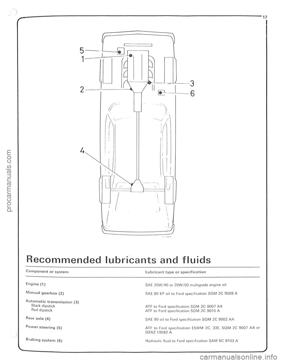
Recommended lubricants and fluids
Component or system
Engine (1)
Manual gearbo x (2)
Autolllatic transmission (3) Black dipstick Red dipstick
Rear ade (4)
POwer steering (5)
Br
SAE 20W/4Q o r 20W/50 multigrade engine 011
SAE 80 EP 0.1 to Ford spee,flctlllon saM 2C 9008 A
ATF 10 Fonl speclliCil tion SOM 2C 9007 AA ATF 10 Fonl specillcmion SOM 2C 9010 A
SAE 90 ad to Ford specI fiCatiOn SaM 2C 9002 AA
ATF to Ford specd 'C[lllon ESW M 2e. 33E. SCM 2C 9007 AA or DZAZ 19582 A
Hydraulic fluid to Ford SpeCifICation SAM GC 9103 A
procarmanuals.com
Page 159 of 205

)8 Chapter 10 Suspension and steering
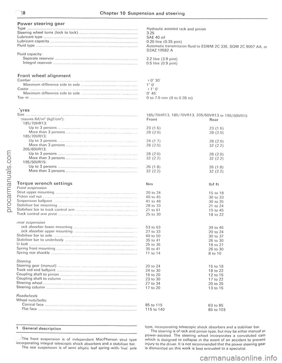
Power steerin g gear Type .. Steer ing wheel turns (lock to lock) lubrican t Iype, Lubricant capacity . Fluid Iype .
Fluid cilpacily: Sepilrilte reservoir . Integli!1 reservoir .
Front wheel alignment C",nbc, M;lXll11um dlffcrence side \0 side C
195/50VR15: Up 10 3 pe.sons . Morc th(ln 3 persons.
Torque wrench settings Fran! SIIS{!cl!siotJ Stlut upper 1110untrng . P,ston rod nut Suspen Sion ')~",{Jont St;rhiliscr birr mount"'lt . Stab iliser h;rr to track control ,)In,
Track cOIHlol ~rrn p,vot
,H'o1( slIspCIlsion od abso,bcr lower mountH'g .ock absorber upper mounting Stabillser bar to axle .. St;rl.lIlIscr har 10 underbody
U ·bol . Sprinu I.ont mount"'g . Spring rear sh;rckle
SINNing Steering gear (m~nual) Track rod end uall,oint Coupling shaft to pinion. Coupling shah t o column . Steering wheel.
Steering column.
Roa(/wiJec/s Wheel nuts/holts: Conicall;rce . FI(lt face.
General description
, -'The flonl suspension is of Independen t MacPherson Strut Iype incorpotating inleglal telescopic shock ~bsorbers and a stabilisel b~r. The ,eal suspens ion is o f semi ellip tic leaf spring·with· 'l ive ' axle Hydrau
l
ic assisted rack tlnd pinion 3.25 SAE 40 oil 0.20 litre (0.35 pint) AulOm
1- 0 ' 30' I" O· I l' O' O ' 45' 01070 nun (0 !O 0 28 ",)
185170HR13. 185/70VRI3. 205/60VR13 o. 195f50VR15 Front Rear
23(1.6) 23 (1 6) 28 (20) 28 (20)
2<1 (1 7) 28 (2.0) 28 (20) 32 (22)
28 (20) 28 (2.0) 32 (22) 32 (22)
26 (1 8) 26 (1.8) 32 (2 2)
32 (22)
N'H Ibl It
20 to 2<1 151018 40 to 45
30 to 33 <11 to <18 30 to 35
28 to 33 21 to 211 21 to 61 15 to <15 25 to 30 18 to 22
53 to 63 39 to 11 13 27 to 33 20 to 2<1 40 to 50 301037 35 to 41 26 to 30 25 to 36 181027 35 to <11 26 to 30 11 to 14 8 to 10
20 to 24 15 to 18 24 to 30 18 to 22 16 to 20
12 to 15 231030 17 to 22 27 to 34 20 to 25 17 to 20 13 to 15
85 to 115 63 to 85
115 to 140 85 to 103
type, incorporating telescopic shock absorbers and ;l stabdiser bill. The steering is of rack and pinion type, but may be either m(lnual or power·assisted . The steering wheel incorporates 11 convoluted cam which is designed to collapse rn the event 01 (In accident to prevent
injur y to Ihe driver. It is not reco mmended that the power steering gear is dismantled on Ihis work is best entrusted to a specialist.
procarmanuals.com
Page 162 of 205

Chapter 10 Suspension and steering 161
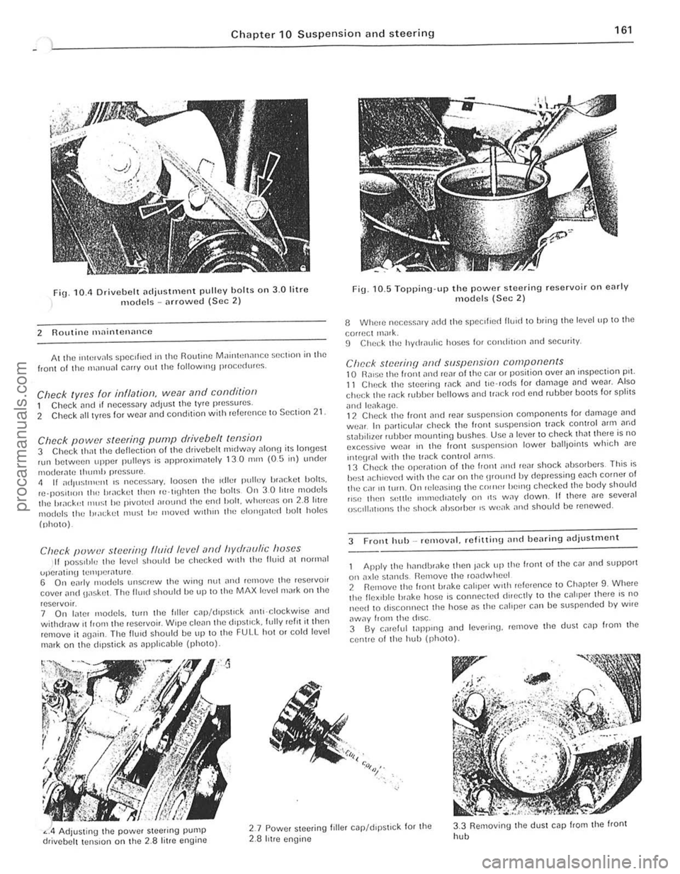
fig. 10.11 Drivebelt [ldjustlllent pulley holts on 3.0 litre models -arrowed (Sec 2)
2 Routine maintenance
At the "*',vals spec ,f,ed III the Routine MainhHlance $()(;t,on in the front of til() manunl c,lIIy out the 101l0wlIl\j p,o(;cdures.
Check lyres for illflalioll, wear and conditioll 1 Check [lnd If necessary adjust the tyre pressures .
2 Check [III t yres for WC[lr and condition with referenc e to Section 21
Check power steering pump drive belt tensiof) 3 Check thm the deflection of the drivebelt m,dway ulon!) its lonyest nlll between upper pulleys is approxirn
(photo).
Clwck puwer steering fluid levef (lnd hydraulic huses II pOSStble the level should be checked w,th the Buid [It nOll1lal
uper,\!mg tClIll)Cr[lture . 6 On c;lrly modcls unscrcw the wing nut nnd relnove Ihe rese,voir cover ilild uaskel. The flu,d should be up 10 Ihe MAX level mark on the
reservo". 7 On later models, wrn tht! hiler C
Fig. 10. 5 Topping·up the power steering reservoir on early models (Sec 2)
8 Whele nec.ess.1'y ~dd Ihe ~pccilled lIU1d to bring Ihe level up to the
correct ,nilrk. 9 ChC(;k the hydr[luhc hoses for comJit,on and security.
Check steerinfj ,-md suspension components 10 n,ll$O tilt) front ilno reM 01 the Cill or position over an inspeclion pn. 11 Check the SleetinlJ wck and t'e 'rods for d[lm3ge und weM. Also check the wek HJbber bellows and track rod end rubber bOOIS for spfilS
ilnd leilk[lge. 12 Chec k the front ,md reilr suspension components lor d"m.Jge [lnd wear. In particuf;lr check the front suspension tr.Jck control Mm ilrod stahiliwr r"bber mounling bushes. Usc a lever to check that there is no excessive we[lr III the Iron I slispenSlon lower IJ[ll lJoints which Me
"'\()\JIill wnh the track conlrol ilflllS . 13 Check the operat,on of the I,ont ;IIHt rear shock absorbers This is
be st ilchievcd with thO} Cilr on the \lfOlind by depressing euch corner of the ca' 1111\I1. On 'ele[lsil\ljthe C()"H~r helllU checked Ihe body should ,,~c thell s"llie IIlIl11ed,mely on ,t~ way down. II there nrc sever.J1 ()sclll;ot'ons the sho(;k absorber IS weilk nnd should be renewed.
3 Front hub _ removal. refitliny and bearing adjustillent
Apply the h[llldhr[lke then Jilek tip the front 01 the cm ilnd support
on axlt! standS Remove til(! rOildwhecl 2 Rernove the front ul;lke CJllper With ,elerence 10 Ch.Jpter 9. Whele the flex,ble br[lke host! is connecte(t dueclly to the cililper ther e IS no need 10 disconnect the hose i1S thO} caliper can be suspcnded by wire
aWily from the diSC. 3 By calelul 1
" :<>,:,~,.
Adjusting the power Sleering pump drivebelt tension on the 2.8 litre engine
2.7 Powcr steeling filler c.Jp/d,pstlck for the 2.8 hIre engine
3.3 Removing the dUSI cap from the front
hob
i
i ,
~ !
procarmanuals.com
Page 203 of 205

2"4 Index
",-----------------------------------------------------------------1 -
ligh\s operation check -16 w~she( fluid levels check/lop up - 16, 217, 219
engine
crankcase emission valve renewal -16, 27
fluid leaks check -16 oil i1nd filter change -16, 26 oil filler cap clClIning -16. 26 oil level check/lop up -16 1I;llvo clearances check/adjust -16. 46
exhaust system condition check -16
fuel sySlCm
removlll and relltting lldjustllble exter ior -192 interior -192
Oil pump
p
28 Iotre engine dismantling. examination and re~sselllhly -38 ref in in 9 -42 3 0 li tre englllc dismantling. eX~lllinmion ilnd reass embly .-52 [elit\lng -54 removill 50
Pedal ,1cceler,ltOr 75 bra k e · 152 clutch -101 Pisto n an d connec ting rods ref,nin\j -42. 51 Pistons and pisto n rin\js exanllna\lon ,1nd rcoova\lon 36,51 Pi sto ns. connecting rod s il11d bearin\js (3.0 litre cngine) [lmlov,11 51 Propeller shaft 128 d s, .'r/ Prop elle r shaft cenlre bcarln!J r()"l]w~1 12!J
descrip1l011 28 I"ul l (i iaunosis - 131 removat and rel,UlI1U -128 10rque wrench seHlIlgs -128 univers~1 10lllts inspection 130 Pushrods 35< 51
R
Rndi,lto r rel11ov~I, Inspcctoon, cie
Rear lamp and b ulb removal and refttling - 216 Rear number plilte lamp and bulb removal ilnd relilling -216 R ear su spension description - 158
procarmanuals.com