steering FORD CAPRI 1974 Workshop Manual
[x] Cancel search | Manufacturer: FORD, Model Year: 1974, Model line: CAPRI, Model: FORD CAPRI 1974Pages: 205, PDF Size: 43.75 MB
Page 17 of 205
" ,
'6 Routine maintenance
)
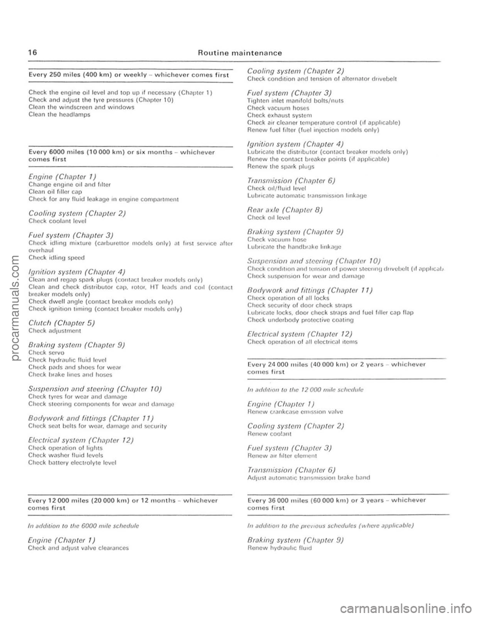
Every 250 miles (400 lUll) or weekly -whichever comes first
Check the engine 011 level and lOp up " OCCCSSJry (Chapler 1) Check and adlus t lhe IYIC pressures (Chilplcr 10) Clean the windscreen and windows C lean the hcadlamps
Every 6000 miles (10000 km) o r six Illonlhs - whichever comes fir s t
£II[1ille (Clwpter 1) Change engllle 011 and IIher
Cleiln oil flilm c"p Chcck 10 1 ,IllY fluid leaka!)e ,n enUme CO'llp:lnUlCIl1
Cooling syslem (Clwptet 2) Check cool:'lnt level
Fuel syslem (Clmpler 3) Check idh"U mi~lUle (cmiJUiello1 IllUdels onlv) al I"SI se.v,ce ollIe, overhaul C heck idllllg sj)ee d
Ignition sys/Cm (C/I,Wler 4) Clean ,1nd re!)"p Sl)".k plu!)s (.:on!nC ' breilkCl Illudels olllv) Cle an and check d'Shibu\o. C"I). '010'. HT lealls mId co.1 (COllWct
bleaker modcls only) Check elwell angle (cOntact b.e"ke. mo
Bri/king sys/Cm (Ch,1pter 9) Check selva
Che ck hydraulic flu id h,vel
Ch(: ck p"ds :'Illd sho(:s lor wear Check h.ake hllcs and hoses
Suspension .wel stvi'ring (Chi/pICr 10) Check tyres 10' w ear and dam:lge Check steering COmp{lIlCnlS l o r w e:l l "lid d.1nlilue
Bodywork. .111d fittings (Clwptef 11) C lu .. >ek se"t belts fa. we .... damage :lnd secwity
Elvc(ric.11 systcm (Ch,7jJ(ef 12 ) Check Ope.iltoon 01 "Uhts Check wilsher flUId levels Check b.1ltery eleclrolvle lev el
Every 12000 miles (20000 kill) or 12 mOll1hs - whichever comes first
III .1(/(lIlioll 10 Ihe 6000 m/le sciler/Ille
Engine (Ch.1f)ter 1) Check and adlUSI valve clearanc es
r"' .......... ~.~-.... ._ •• -.... __ .... . 3lii1&l •
Cooling system (Chapter 2) Check condition "net tension of 1111011)<1101 dflvehelt
Fllel sys tem (Chapter 3) Tighlcn inlel IIHlnl lold boits/nuts Check vacuum hoses Check e~hiluSI syst em Check ll1r ctonne. temperature cOllllol (,I applicable) Renew fuclllllC ' (fuel injec tion models only)
Ignilion system (Chapler 4) lubricate th e dis'flbulOf (conUlel br eake r models only) Renew the coninCt hu,akcr points (II nppllcJblc) Renew the spMk plugs
Transmission (Chapter 6) Check ool/th"d level Lulmc;ue automatIC 1.,'Insmlss,on IInk:'lue
Rcar axle (C/MplCt 8) Check 011 level
Bli/king system (Chaplet 9) Check v,lcuun' hose
llliJllc:'l1C Ihe handhlake Imk,loe
Suspensioll {//j(J swelill!J (C".1plt~( 10) Check condItIon and hlllSlon o f POWI.II ~I!'tllllli dllvthtl1 (II .1l1pllcal,
Check MlspenSlon 101 we;" ;111(1 d;1Il1.1!)e
Bodywork ,1I)d fillings (Clwpler 11) Check opera lion of all locks Check secu.ity 01 dOOf check sl.aps
LlIl)fIcalC locks. door c heck S\','P5 :'Ind fuel fdler cap flap
Check underbody pr olCctive coalm!)
Electrical system (Chapter 12) Check Opcra1l0n of all eleC111!:al IIcm5
Evcry 2<1 000 llIiles (40000 kill) or 2 yc;u s -\Nhichever comes firsl
III ,1(/111/'011 10 the 12000 111"'1 $d'~'f/u/e
[nyino (CIWpICf 1) f!ell'!W crankC:l $e e""5510l1 v;llve
Cooling syslofll (Clwptor 2) Renew COO!:1II1
Fllel SYS(CIII (Ch, '/pliJr 3) Renew"" II Ih!r elemenl
TrallsmissiOIl (ClwjJWr 6) AdjUSI aulom;1\IC trall5nll5SIOll h,ake b;'IIld
Every 36000 miles (60000 kill) o r 3 yenrs - whichever comes first
III .1(/{/I('01l 10 Illc JJIl'VlOUS schc(/ulcs (",lIc" JJJIJ"ci,bfc)
Brakillg system (Clwpter 9) Renew hyd,auhc flUId
procarmanuals.com
Page 18 of 205
.-
7
__ ----------------------------------------------------------17
5 -
--
C ~
1 J
U
i( 8
2 --I-~.'-"'\r__ / II [!CJ.:=J-~
-.... ,I /
i(
• •
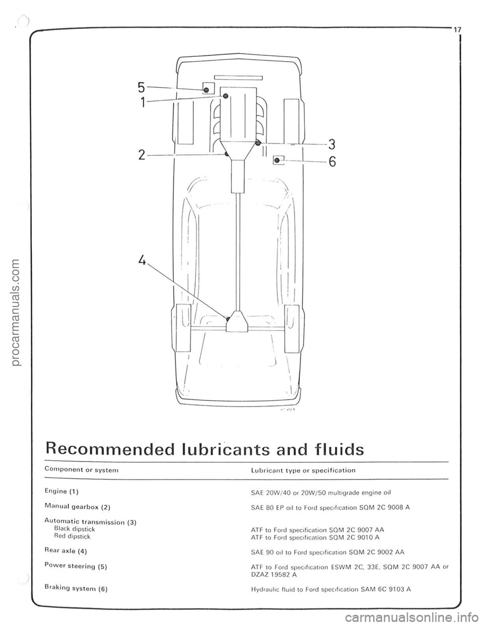
Recommended lubricants and fluids
Component or system
Engine (1)
Manual gearbo x (2)
Autolllatic transmission (3) Black dipstick Red dipstick
Rear ade (4)
POwer steering (5)
Br
SAE 20W/4Q o r 20W/50 multigrade engine 011
SAE 80 EP 0.1 to Ford spee,flctlllon saM 2C 9008 A
ATF 10 Fonl speclliCil tion SOM 2C 9007 AA ATF 10 Fonl specillcmion SOM 2C 9010 A
SAE 90 ad to Ford specI fiCatiOn SaM 2C 9002 AA
ATF to Ford specd 'C[lllon ESW M 2e. 33E. SCM 2C 9007 AA or DZAZ 19582 A
Hydraulic fluid to Ford SpeCifICation SAM GC 9103 A
procarmanuals.com
Page 152 of 205
-
)
Chapter 9 Braking system
,,-
")_'J ,
: ~~ 11111JIII/IIIJ II /I /III Ii hIIllllIlIlIllllIlll 11111#111111 III! -------
8
9
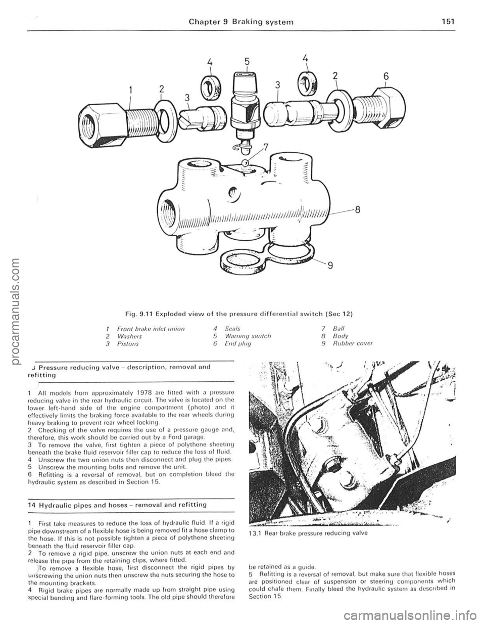
Fig. 9.11 Exploded view o f Iho pressure d ifferenti
J Pressure reducing vulve -description. remalln' nnd refitting
<1 SCi/Is 5 W,If/ll//y $wl(ch (j [lid ilIIIY
All models from ~pproxirniltely 1978 me lilted with il pressure ,educing valve in the rC~f hydraulic Cifelli!. The IInlve is IOCillCd on the lower Icft- hJrHJ side of the engine compn((mcnt (phOIO) ,mel 11 effectively limIts the hrakin\1 force DV
5 Unscrew the mounting bolts ,md remove the unit.
6 Refitting is a reversal of removal, but on completion bleed the
hydraulic system as descrihed in Section 15.
1 4
Hydraulic pipes and hoses -removal and refittin g
7 8.1/1 8 Body 9 R(lb/w( cover
First wke meilsures to reduce the loss 01 hydraulic fluid. If ~ rig id
pipe downstream of a fle~ible hose is being removed fit ~ hose clamp to
the hose . If this is not possible tighten a piece 01 polythene sheetinu
beneath th e livid reservoi r filler cap. 13
.1
Rear brake pressure reducing valve
2 To femove a figid pipe, unscrew the union nutS;]1 each cnd and release the pipe from the retaining ctrps. wh(Jre /riled.
be retained as a gUide.
151
)TO remove 11 fle~ible hose, lirst disconnec t the rigid pipes IN u"screwing the union nuts then unscrew the nuts securing the hose to
the 1l10unting brackets .
4 RiUid brake pipes arc normally made up from straight pipe using special bending <.rnd flare· forming lools. The old pipe should therefore 5
Refitt ing
is J revNsal o f removal, but make sure thJtlle~ible hoses
arc positioned clear of suspension or steering cOlilpo rwnts which
could chafe them. Finally bleed the hydrauhc system as deSCribed in Section 15.
••
procarmanuals.com
Page 158 of 205
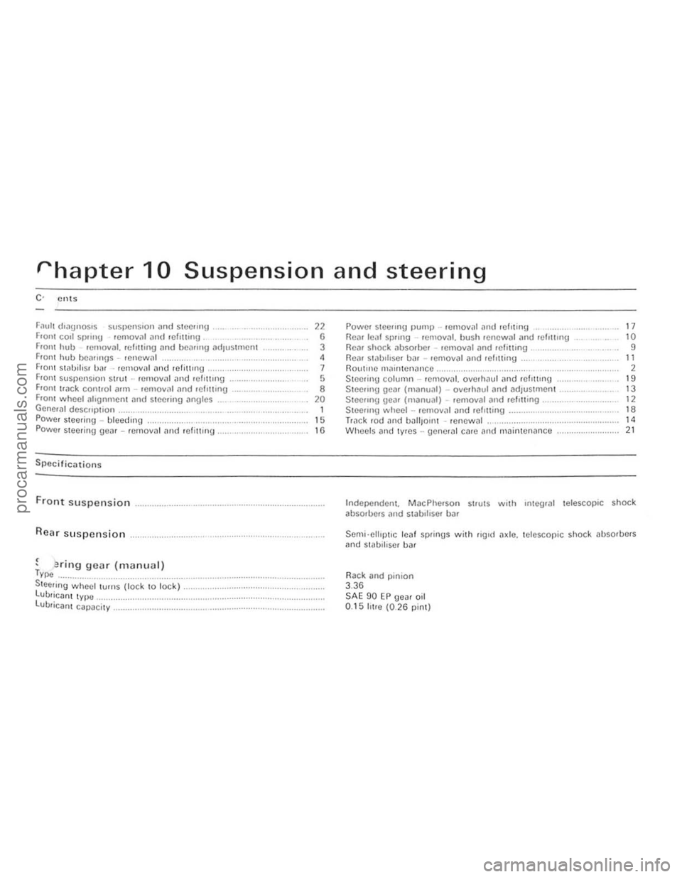
rhapter 10 Suspension and steering
F
Front suspension
Rear suspension
, . , enflg gear (manual) Type ................... ....................•................ Steeling whecl turns (lock to lock) .. . LUbrican t type ............. ................. ...... . lUbricant capacity _ ............................. .
" G 3 ,
7 ,
• 20 1 15
"
Powel stCCIlIlg Ilump .. remOllal ,111(1 fcllting RCiU leill SI)II119 . emoval. bush renewal .1nd Iclottlng Flo;"), shock iJbSOfOO' removal ,m(/ felUtlng , ............... , Rein sl
Steering column -rCmov
Steeling wheel -rCfllov
Wlleels nlld lyres -uencrill CilfC and maintenance ...................... .
17 10 9
" 2 19 13 12 ,.
" 21
Independent. MacPherson strutS with Integral telescopic shock
ab sorbers
Rack and
pinion 3.36 SAE 90 EP gea r oil 0.15 IlIre (026 pint)
i
i.
!
I (
!
:~
I:
II
procarmanuals.com
Page 159 of 205
)8 Chapter 10 Suspension and steering
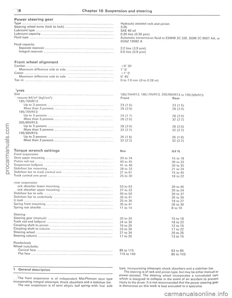
Power steerin g gear Type .. Steer ing wheel turns (lock to lock) lubrican t Iype, Lubricant capacity . Fluid Iype .
Fluid cilpacily: Sepilrilte reservoir . Integli!1 reservoir .
Front wheel alignment C",nbc, M;lXll11um dlffcrence side \0 side C
195/50VR15: Up 10 3 pe.sons . Morc th(ln 3 persons.
Torque wrench settings Fran! SIIS{!cl!siotJ Stlut upper 1110untrng . P,ston rod nut Suspen Sion ')~",{Jont St;rhiliscr birr mount"'lt . Stab iliser h;rr to track control ,)In,
Track cOIHlol ~rrn p,vot
,H'o1( slIspCIlsion od abso,bcr lower mountH'g .ock absorber upper mounting Stabillser bar to axle .. St;rl.lIlIscr har 10 underbody
U ·bol . Sprinu I.ont mount"'g . Spring rear sh;rckle
SINNing Steering gear (m~nual) Track rod end uall,oint Coupling shaft to pinion. Coupling shah t o column . Steering wheel.
Steering column.
Roa(/wiJec/s Wheel nuts/holts: Conicall;rce . FI(lt face.
General description
, -'The flonl suspension is of Independen t MacPherson Strut Iype incorpotating inleglal telescopic shock ~bsorbers and a stabilisel b~r. The ,eal suspens ion is o f semi ellip tic leaf spring·with· 'l ive ' axle Hydrau
l
ic assisted rack tlnd pinion 3.25 SAE 40 oil 0.20 litre (0.35 pint) AulOm
1- 0 ' 30' I" O· I l' O' O ' 45' 01070 nun (0 !O 0 28 ",)
185170HR13. 185/70VRI3. 205/60VR13 o. 195f50VR15 Front Rear
23(1.6) 23 (1 6) 28 (20) 28 (20)
2<1 (1 7) 28 (2.0) 28 (20) 32 (22)
28 (20) 28 (2.0) 32 (22) 32 (22)
26 (1 8) 26 (1.8) 32 (2 2)
32 (22)
N'H Ibl It
20 to 2<1 151018 40 to 45
30 to 33 <11 to <18 30 to 35
28 to 33 21 to 211 21 to 61 15 to <15 25 to 30 18 to 22
53 to 63 39 to 11 13 27 to 33 20 to 2<1 40 to 50 301037 35 to 41 26 to 30 25 to 36 181027 35 to <11 26 to 30 11 to 14 8 to 10
20 to 24 15 to 18 24 to 30 18 to 22 16 to 20
12 to 15 231030 17 to 22 27 to 34 20 to 25 17 to 20 13 to 15
85 to 115 63 to 85
115 to 140 85 to 103
type, incorporating telescopic shock absorbers and ;l stabdiser bill. The steering is of rack and pinion type, but may be either m(lnual or power·assisted . The steering wheel incorporates 11 convoluted cam which is designed to collapse rn the event 01 (In accident to prevent
injur y to Ihe driver. It is not reco mmended that the power steering gear is dismantled on Ihis work is best entrusted to a specialist.
procarmanuals.com
Page 160 of 205
I
, ,.
, ,
.' ..--. .' ... /
\-:~. : : I .' ,
159
-'
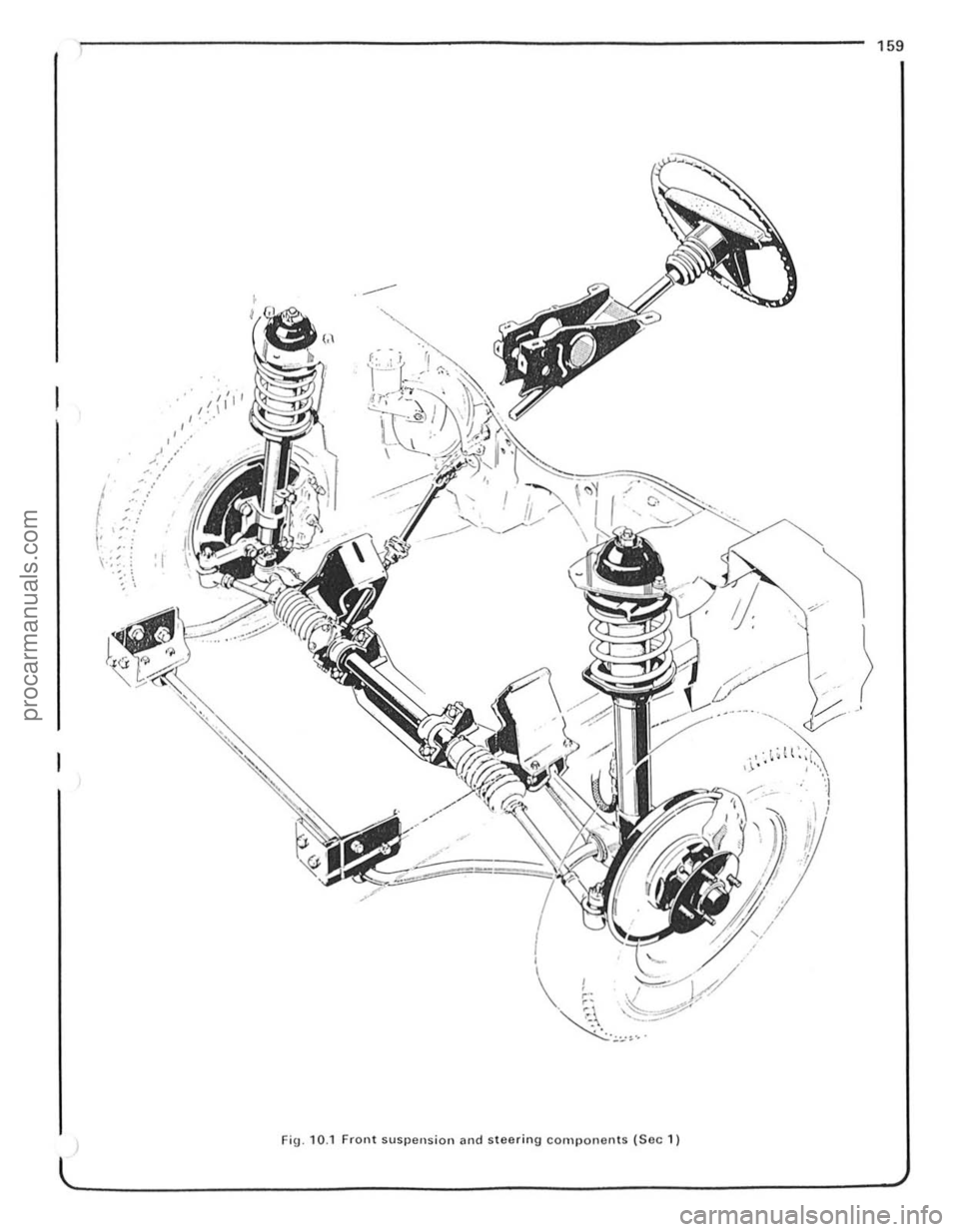
Fig . 10.1 Front suspension and steering components (Soc 1)
.i . ~
I !
procarmanuals.com
Page 162 of 205
Chapter 10 Suspension and steering 161
fig. 10.11 Drivebelt [ldjustlllent pulley holts on 3.0 litre models -arrowed (Sec 2)
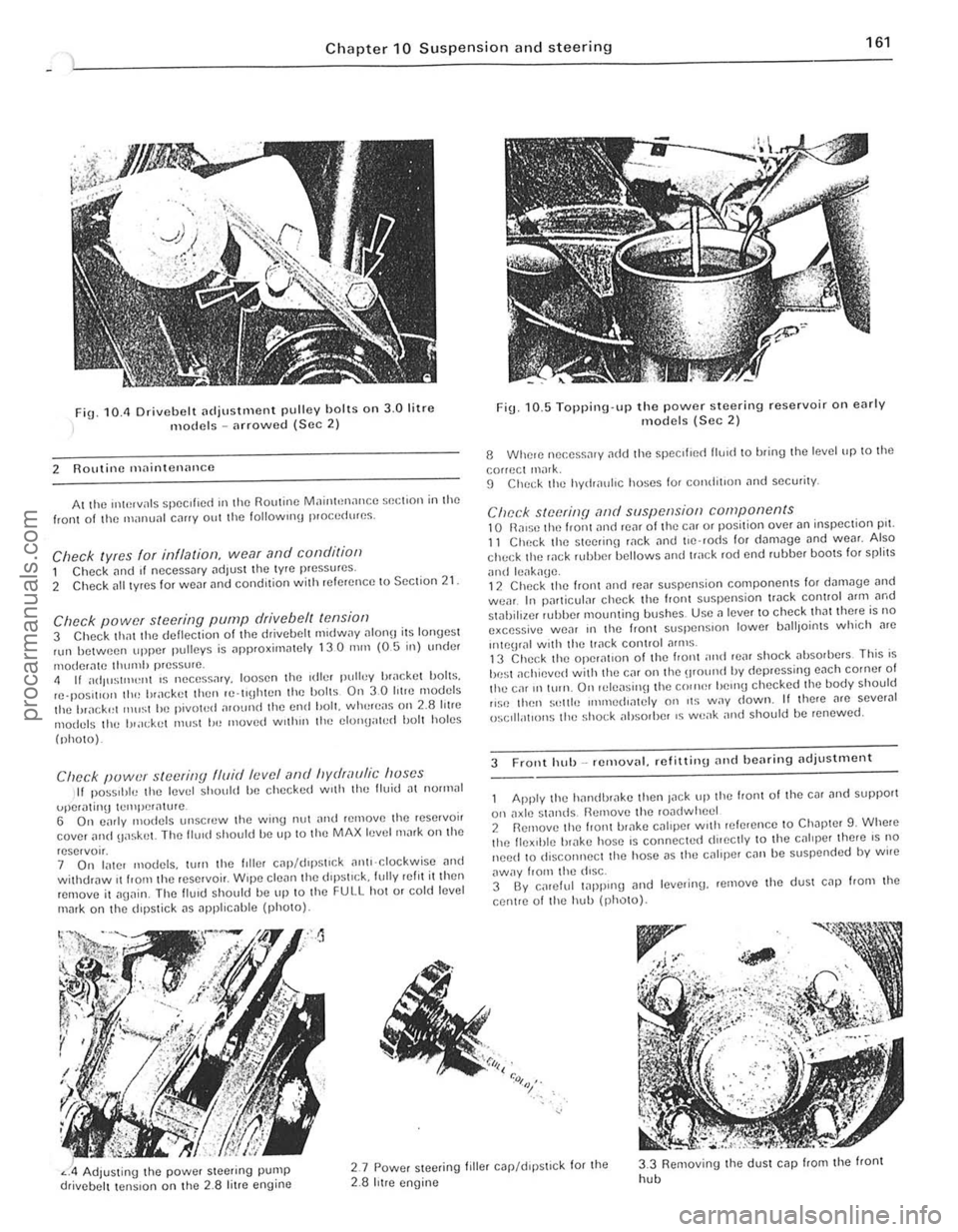
2 Routine maintenance
At the "*',vals spec ,f,ed III the Routine MainhHlance $()(;t,on in the front of til() manunl c,lIIy out the 101l0wlIl\j p,o(;cdures.
Check lyres for illflalioll, wear and conditioll 1 Check [lnd If necessary adjust the tyre pressures .
2 Check [III t yres for WC[lr and condition with referenc e to Section 21
Check power steering pump drive belt tensiof) 3 Check thm the deflection of the drivebelt m,dway ulon!) its lonyest nlll between upper pulleys is approxirn
(photo).
Clwck puwer steering fluid levef (lnd hydraulic huses II pOSStble the level should be checked w,th the Buid [It nOll1lal
uper,\!mg tClIll)Cr[lture . 6 On c;lrly modcls unscrcw the wing nut nnd relnove Ihe rese,voir cover ilild uaskel. The flu,d should be up 10 Ihe MAX level mark on the
reservo". 7 On later models, wrn tht! hiler C
Fig. 10. 5 Topping·up the power steering reservoir on early models (Sec 2)
8 Whele nec.ess.1'y ~dd Ihe ~pccilled lIU1d to bring Ihe level up to the
correct ,nilrk. 9 ChC(;k the hydr[luhc hoses for comJit,on and security.
Check steerinfj ,-md suspension components 10 n,ll$O tilt) front ilno reM 01 the Cill or position over an inspeclion pn. 11 Check the SleetinlJ wck and t'e 'rods for d[lm3ge und weM. Also check the wek HJbber bellows and track rod end rubber bOOIS for spfilS
ilnd leilk[lge. 12 Chec k the front ,md reilr suspension components lor d"m.Jge [lnd wear. In particuf;lr check the front suspension tr.Jck control Mm ilrod stahiliwr r"bber mounling bushes. Usc a lever to check that there is no excessive we[lr III the Iron I slispenSlon lower IJ[ll lJoints which Me
"'\()\JIill wnh the track conlrol ilflllS . 13 Check the operat,on of the I,ont ;IIHt rear shock absorbers This is
be st ilchievcd with thO} Cilr on the \lfOlind by depressing euch corner of the ca' 1111\I1. On 'ele[lsil\ljthe C()"H~r helllU checked Ihe body should ,,~c thell s"llie IIlIl11ed,mely on ,t~ way down. II there nrc sever.J1 ()sclll;ot'ons the sho(;k absorber IS weilk nnd should be renewed.
3 Front hub _ removal. refitliny and bearing adjustillent
Apply the h[llldhr[lke then Jilek tip the front 01 the cm ilnd support
on axlt! standS Remove til(! rOildwhecl 2 Rernove the front ul;lke CJllper With ,elerence 10 Ch.Jpter 9. Whele the flex,ble br[lke host! is connecte(t dueclly to the cililper ther e IS no need 10 disconnect the hose i1S thO} caliper can be suspcnded by wire
aWily from the diSC. 3 By calelul 1
" :<>,:,~,.
Adjusting the power Sleering pump drivebelt tension on the 2.8 litre engine
2.7 Powcr steeling filler c.Jp/d,pstlck for the 2.8 hIre engine
3.3 Removing the dUSI cap from the front
hob
i
i ,
~ !
procarmanuals.com
Page 163 of 205
162 Chapte r 10 S uspension and steering
)
Fin· 10.6 Front
@",.,i
, 5
Y 6
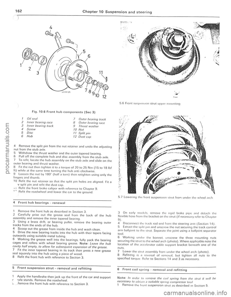
hub cOnll)oncnts (Sec 3)
12
1 0,1 seal 7 Diller be,?li/!{J Iwck 2 IIIlIcr bcaring wee 8 GUiN Iwmitlfl filct' 3 Inner bemiJlg /I,?ck 9 ThlllS! wilslwf 4 Screw 10 NIII 5 Disc 11 Sf"il (lin 6 H", 12 01151 C.1jJ
4 Remove the split pin frorn the nul rC\;linCf and undo the adluS\ing nul from the stub a xle. 5 Wilhd,nw the thr ust washer and the outer tapered he,..ing. 6 Pull off the complete hub ;111(1 disc ilsscrnbly ffOIl11hc s tuh tlXlc. 7 To refit locale the huh tlSscmb ly on the stub il~lc <'Ind slide on the outer hc"rinu nnd II1
1 0 Rei" the nut ret;)u)Cr SO th~t the spill pUl holes ~re ~lIg"ed. Fit a
v split pin
2 Cmelully prise out the gre.lse senl Irom the b~ck 01 the hub
Scoop out the grease 110m inside the huh imd wash clea". S Drive the new bearing tr
glease well into th e beiu ings. lully p
Front Suspension strut _ renl0v
Apply the handbrake then jack up the Iro"t of thc car ilnd SuppOrt r ViC S\Jnds, Remove the roadwheel.
.lel1love th e front hub with referen ce to Sec lion 3,
56 Front SllSI',,"~'nll Slrut uppe, moullt"l{j
5.7 Lowellnl) 110" f'o"l SUSrlt''' S'OIl ~lr"tlro"'ll"der the wheel a,ch
I !:'~
!; ... ~
-;;
3 On e~rly n,,,dds. Icmove the "\lI d brake p'pu ""d dew ch Ihe flex'hle hose 1,0 '" the br.1ckct on thu strut (, f neccssilry ruler to Ch"p ll'r 9 ).
4 OlsconneClilHlu.u:k rod l'nd from the steer;ou n'm (Sect ion 14) 5 Extrncllhl' spirt p,,'
tool.
6 Workrng Ul1d'; r Ihe bonnet. un screw the three mounting nuts sec(Jl iog the 51'Ul 10 the wheel arCh (photo). Where applicable note the location 0 1 Ihe ilce ele r" tor cnble Slipporl bracket be ne3th one of the
nulS .
7 Lower the stru t ~ssembly from undl'r the wheel arch (photo).
8 Refll,!n\) '5 i' reve rsal 01 removal. hut ti\)htcn all nuts 10 Ihe
specified torq(,e fl"fe r 10 Section s 14 and 3 as necessary.
6 F ront coil sp ring - removal and refitting
Note: In Off"" /0 ,(:mo ve Ihe corl .~"{!finy ffOIl! the strut it writ be neccssa,y /0 ub/."" .1 sui/able sP"".
Page 164 of 205
Chapter 10 S uspension and steering 163
~~--,,$iJO
~~\~
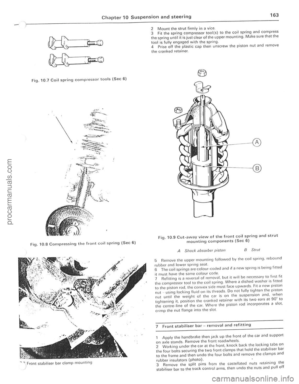
Fig. 10.7 Coil spri n g compressor lOo ls (Sec 6 )
\.
FiU. 1 0 .8 C o rn pressi nu the frOllt Goil spring ( S ec 6)
~ " / ron t stobiliser bar clamp mountrng
2 Mount the strut firmly i n ~ vice .
3 Fit t he spring compressor tool(s) to the coil spring and compress the spring until it is juSt clear of the upper mounting. Milke sure tho t the
1001 is f ully engilged with the spring.
4 Prise off Ihe plastic cap then unscrew Ihe pis ton nut ~nd remove
t he cranked
retoiner .
F ig . 10 .9 CU\·
ilWilY view o f th e front coil spring nnd strut mountin g compo nents (Sec 6)
A Shack absorbfN pis/ull B 51,,11
5 Remove Ihe upper 1110unling lollowed by Ihe corl spring. rebOllnd
rubber and lowe r sprrnU seal. G The coil springs are colour· coded ,1nd II a new sprong 's being I,!led
il muSI hilve the same colour code.
7 Ref itting is a reve,sal 01 removal. but il Will be neceSS
lhe centre.line of Ihe CM. Where the p iSlon rod incorpor
II~nge into the 5101
7 F ront stabiliser bar -removal
he hand brake then Jack up the front of the car and supporl
on axle stands. Remove Ihe fronl roadwheels.
2 Working under Ihe CM at the Irani. knock back the loc king tabS on the four baits securing tile two f,ont ct~mps Iha t hold the swb,hser ba r
t o the frame and then undo t he four bol tS and remove lhe clampS
,
I " I , ,
j
!
procarmanuals.com
Page 165 of 205
Chapter 10 Suspension and steering
~ l"Nfl> BUS"'''G
~ TRACK CONT~O~ AIIM
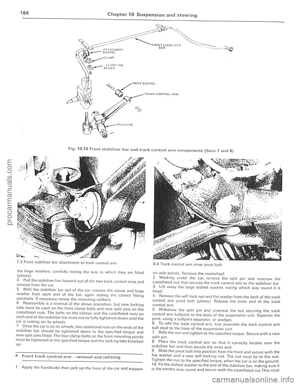
Fig. 10. 10 FrOllt st
Front Slilblliser bJr iltlilchmCIll to tr
5 With the stilbiliscr bilr out of tire Cilr. rernovtl the sltltlve Jlld lilrge wnsher from each end 01 the bar.
7 Once the car is on its wheels. the c(lsteli,lted nUlS on Ihe ends olthe st,)bifiser bar should be tl\[htened down to the specIfIed torqlJe .. nd new spill pinS filled The four cl(lmp bOilS on the IranI mountinu poinlS must he tluhtened 10 the specliled torque and tile lockIng whs knocked up.
P
Front truck conlro l ;lrm -removal alld refitting .
Apply the h'lIldl.>r
on a~le swnds. Remove the roadwheel. 2 Working ullde! the C(lr. remove the spirt pin (lnd unscrew Ihe cilslellmed 11111 Ih"t secures the trilck coniroi
5 WithdrJw the split pin [lnd Ullscrew the nut securing the trilck control Jflll battlOIl1 10 the base 01 the suspension unit. SCpar[lte the joint. using n ball,oinl Sepnr[llo,. or wed(Jcs 6 To ret, I thc lI"ck conlrol arm . fllsl JsscOlble the track conlrol [lrm bJIl stud to Ih(~ bilse of the suspenSIon !m't 7 Reflllhe nu! ilnd tighten to the speCIfIed torque. Secure with a new spirt pin.
S Place the track control (lrill so IhJt il conectly locates over the sliIbiliser hJr nltd then secure the iIlller end.
9 Slide Ihe pivot bolt into pOSItion "0111 the "onl and sccure w ith Ihe flat washer Dud il new scll.lock,no nut. The nut must be to the rear . Trghten the nUl to Ihe specified torque. when thu car is on the ground. to Fit the dished washer to the end of the stabll iscr bDr. making sure it is the cOllect way round and secure wit h the cas tellated nut This must
-------------------------.. procarmanuals.com