low FORD E-350 2012 Owners Manual
[x] Cancel search | Manufacturer: FORD, Model Year: 2012, Model line: E-350, Model: FORD E-350 2012Pages: 335, PDF Size: 2.63 MB
Page 207 of 335
1 (First)
•Provides maximum engine braking.
•Allows upshifts by moving gearshift lever.
•The transmission will not downshift into 1 (First) at high speeds; it
will downshift to a lower gear and then shift into 1 (First) when the
vehicle reaches slower speeds.
Forced downshifts
•Allowed in
(Overdrive) or Drive.
•Press the accelerator to the floor.
•Allows transmission to select an appropriate gear.
If your vehicle goes off the edge of the pavement
•If your vehicle goes off the edge of the pavement, slow down, but
avoid severe brake application, ease the vehicle back onto the
pavement only after reducing your speed. Do not turn the steering
wheel too sharply while returning to the road surface.
•It may be safer to stay on the apron or shoulder of the road and slow
down gradually before returning to the pavement. You may lose
control if you do not slow down or if you turn the steering wheel too
sharply or abruptly.
•It often may be less risky to strike small objects, such as highway
reflectors, with minor damage to your vehicle rather than attempt a
sudden return to the pavement which could cause the vehicle to slide
sideways out of control or roll over. Remember, your safety and the
safety of others should be your primary concern.
WARNING:Vehicles with a higher center of gravity such as
utility and four-wheel drive vehicles handle differently than
vehicles with a lower center of gravity. Utility and four-wheel drive
vehicles arenotdesigned for cornering at speeds as high as passenger
cars any more than low-slung sports cars are designed to perform
satisfactorily under off-road conditions. Avoid sharp turns, excessive
speed and abrupt maneuvers in these vehicles. Failure to drive
cautiously could result in an increased risk of loss of vehicle control,
vehicle rollover, personal injury and death.
Driving
207
2012 Econoline(eco)
Owners Guide, 1st Printing
USA(fus)
ProCarManuals.com
Page 209 of 335
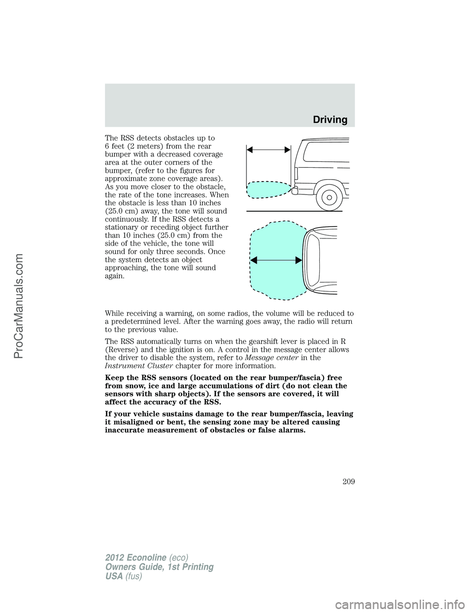
The RSS detects obstacles up to
6 feet (2 meters) from the rear
bumper with a decreased coverage
area at the outer corners of the
bumper, (refer to the figures for
approximate zone coverage areas).
As you move closer to the obstacle,
the rate of the tone increases. When
the obstacle is less than 10 inches
(25.0 cm) away, the tone will sound
continuously. If the RSS detects a
stationary or receding object further
than 10 inches (25.0 cm) from the
side of the vehicle, the tone will
sound for only three seconds. Once
the system detects an object
approaching, the tone will sound
again.
While receiving a warning, on some radios, the volume will be reduced to
a predetermined level. After the warning goes away, the radio will return
to the previous value.
The RSS automatically turns on when the gearshift lever is placed in R
(Reverse) and the ignition is on. A control in the message center allows
the driver to disable the system, refer toMessage centerin the
Instrument Clusterchapter for more information.
Keep the RSS sensors (located on the rear bumper/fascia) free
from snow, ice and large accumulations of dirt (do not clean the
sensors with sharp objects). If the sensors are covered, it will
affect the accuracy of the RSS.
If your vehicle sustains damage to the rear bumper/fascia, leaving
it misaligned or bent, the sensing zone may be altered causing
inaccurate measurement of obstacles or false alarms.
Driving
209
2012 Econoline(eco)
Owners Guide, 1st Printing
USA(fus)
ProCarManuals.com
Page 210 of 335
REARVIEW CAMERA SYSTEM (IF EQUIPPED)
The rearview camera system located
on the back door provides a video
image, which appears in the
rearview mirror or navigation screen
(if equipped), of the area behind the
vehicle. It adds assistance to the
driver while reversing or reverse
parking the vehicle.
To use the camera system, place the transmission in R (Reverse); an
image will display on the left portion of the rearview mirror or on the
navigation screen (if equipped). The area displayed on the screen may
vary according to the vehicle orientation and/or road condition.
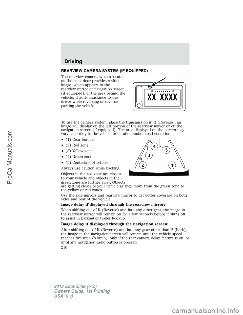
•(1) Rear bumper
•(2) Red zone
•(3) Yellow zone
•(4) Green zone
•(5) Centerline of vehicle
Always use caution while backing.
Objects in the red zone are closest
to your vehicle and objects in the
green zone are further away. Objects
are getting closer to your vehicle as they move from the green zone to
the yellow or red zones.
Use the side mirrors and rearview mirror to get better coverage on both
sides and rear of the vehicle.
Image delay if displayed through the rearview mirror:
When shifting out of R (Reverse) and into any other gear, the image in
the rearview mirror will remain on for a few seconds before it shuts off
to assist in parking or trailer hookup.
Image delay if displayed through the navigation screen:
After shifting out of R (Reverse) and into any gear other than P (Park),
the image in the navigation screen will remain until the vehicle speed
reaches five mph (8 km/h), only if the rear camera delay feature is on, or
until any navigation radio button is pressed.
Driving
210
2012 Econoline(eco)
Owners Guide, 1st Printing
USA(fus)
ProCarManuals.com
Page 211 of 335
Note:The default setting for the rear camera delay is off. Press the
“Settings” button found on the navigation screen (if equipped) to set the
rear camera delay feature to on or off.
When towing, the camera system will only see what is being towed
behind the vehicle; this might not provide adequate coverage as it
usually provides in normal operation and some objects might not be
seen.
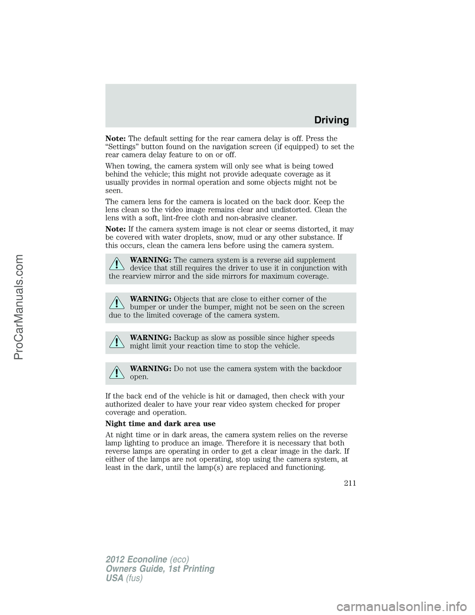
The camera lens for the camera is located on the back door. Keep the
lens clean so the video image remains clear and undistorted. Clean the
lens with a soft, lint-free cloth and non-abrasive cleaner.
Note:If the camera system image is not clear or seems distorted, it may
be covered with water droplets, snow, mud or any other substance. If
this occurs, clean the camera lens before using the camera system.
WARNING:The camera system is a reverse aid supplement
device that still requires the driver to use it in conjunction with
the rearview mirror and the side mirrors for maximum coverage.
WARNING:Objects that are close to either corner of the
bumper or under the bumper, might not be seen on the screen
due to the limited coverage of the camera system.
WARNING:Backup as slow as possible since higher speeds
might limit your reaction time to stop the vehicle.
WARNING:Do not use the camera system with the backdoor
open.
If the back end of the vehicle is hit or damaged, then check with your
authorized dealer to have your rear video system checked for proper
coverage and operation.
Night time and dark area use
At night time or in dark areas, the camera system relies on the reverse
lamp lighting to produce an image. Therefore it is necessary that both
reverse lamps are operating in order to get a clear image in the dark. If
either of the lamps are not operating, stop using the camera system, at
least in the dark, until the lamp(s) are replaced and functioning.
Driving
211
2012 Econoline(eco)
Owners Guide, 1st Printing
USA(fus)
ProCarManuals.com
Page 213 of 335
VEHICLE USED AS A STATIONARY POWER SOURCE
Auxiliary equipment called power take-off or PTO, is often added to the
engine or transmission to operate utility equipment. Examples include a
wheel-lift for tow trucks, cranes, tools for construction or tire service and
pumping fluids. PTO applications draw auxiliary horsepower from the
powertrain, often while the vehicle is stationary. In this condition, there
is limited cooling air flow through the radiator and around the vehicle
that normally occurs when a vehicle is moving. The aftermarket PTO
system installer, having the most knowledge of the final application, is
responsible for determining whether additional chassis heat protection or
powertrain cooling is required, and alerting the user to the safe and
proper operation.
Your vehicle is qualified for use as a stationary power source, within
limits detailed in theFord Truck Body Builders Layout Book,found at
www.fleet.ford.com/truckbbas, and through the Ford Truck Body Builders
Advisory Service.
Gas engine vehicles are qualified for up to 10 minutes of continuous
operation as a stationary power source, due to the potential for the
normal venting of fuel vapors. Further consult your aftermarket PTO
installer, since the duration of operation limit for the aftermarket PTO
may be less than the vehicle is capable of.
DRIVING THROUGH WATER
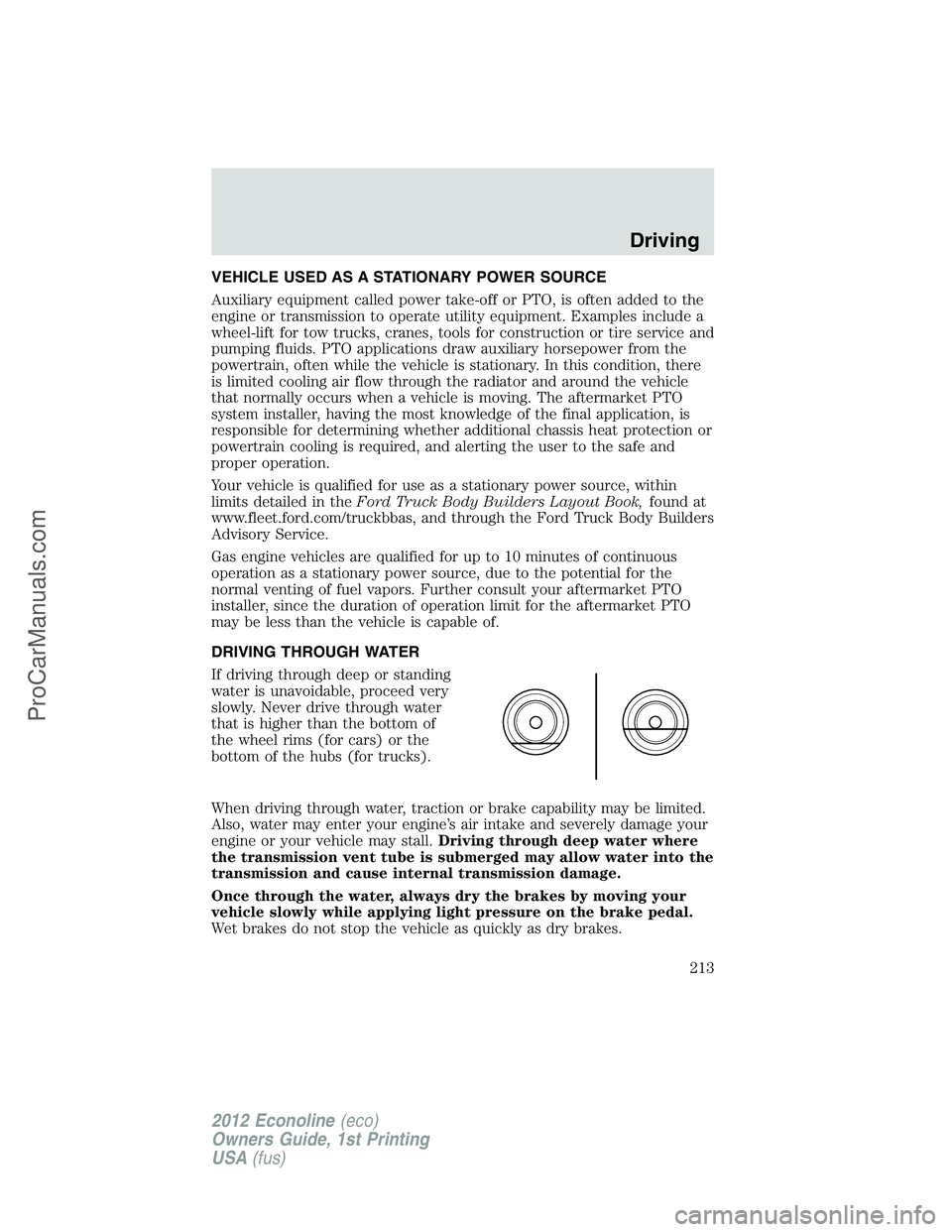
If driving through deep or standing
water is unavoidable, proceed very
slowly. Never drive through water
that is higher than the bottom of
the wheel rims (for cars) or the
bottom of the hubs (for trucks).
When driving through water, traction or brake capability may be limited.
Also, water may enter your engine’s air intake and severely damage your
engine or your vehicle may stall.Driving through deep water where
the transmission vent tube is submerged may allow water into the
transmission and cause internal transmission damage.
Once through the water, always dry the brakes by moving your
vehicle slowly while applying light pressure on the brake pedal.
Wet brakes do not stop the vehicle as quickly as dry brakes.
Driving
213
2012 Econoline(eco)
Owners Guide, 1st Printing
USA(fus)
ProCarManuals.com
Page 216 of 335
FUEL PUMP SHUT-OFF (EXCEPT STRIPPED CHASSIS)
In the event of a moderate to severe collision, this vehicle is equipped
with a fuel pump shut-off feature that stops the flow of fuel to the
engine. Not every impact will cause a shut-off.
Should your vehicle shut off after a collision due to this feature, you may
restart your vehicle by doing the following:
1. Turn the ignition switch to the off position.
2. Turn the ignition switch to the on position.
In some instances the vehicle may not restart the first time you try to
restart and may take one additional attempt.
WARNING:Failure to inspect and if necessary repair fuel leaks
after a collision may increase the risk of fire and serious injury.
Ford Motor Company recommends that the fuel system be inspected
by an authorized dealer after any collision.
FUEL PUMP SHUT-OFF SWITCH (STRIPPED CHASSIS VEHICLES
ONLY)
This device stops the electric fuel pump from sending fuel to the engine
when your vehicle has had a substantial jolt.
After an accident, if the engine cranks but does not start, this switch
may have been activated.
Roadside Emergencies
216
2012 Econoline(eco)
Owners Guide, 1st Printing
USA(fus)
ProCarManuals.com
Page 217 of 335
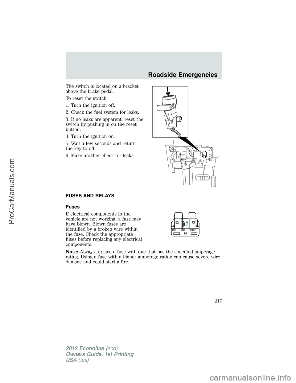
The switch is located on a bracket
above the brake pedal.
To reset the switch:
1. Turn the ignition off.
2. Check the fuel system for leaks.
3. If no leaks are apparent, reset the
switch by pushing in on the reset
button.
4. Turn the ignition on.
5. Wait a few seconds and return
the key to off.
6. Make another check for leaks.
FUSES AND RELAYS
Fuses
If electrical components in the
vehicle are not working, a fuse may
have blown. Blown fuses are
identified by a broken wire within
the fuse. Check the appropriate
fuses before replacing any electrical
components.
Note:Always replace a fuse with one that has the specified amperage
rating. Using a fuse with a higher amperage rating can cause severe wire
damage and could start a fire.
15
Roadside Emergencies
217
2012 Econoline(eco)
Owners Guide, 1st Printing
USA(fus)
ProCarManuals.com
Page 218 of 335
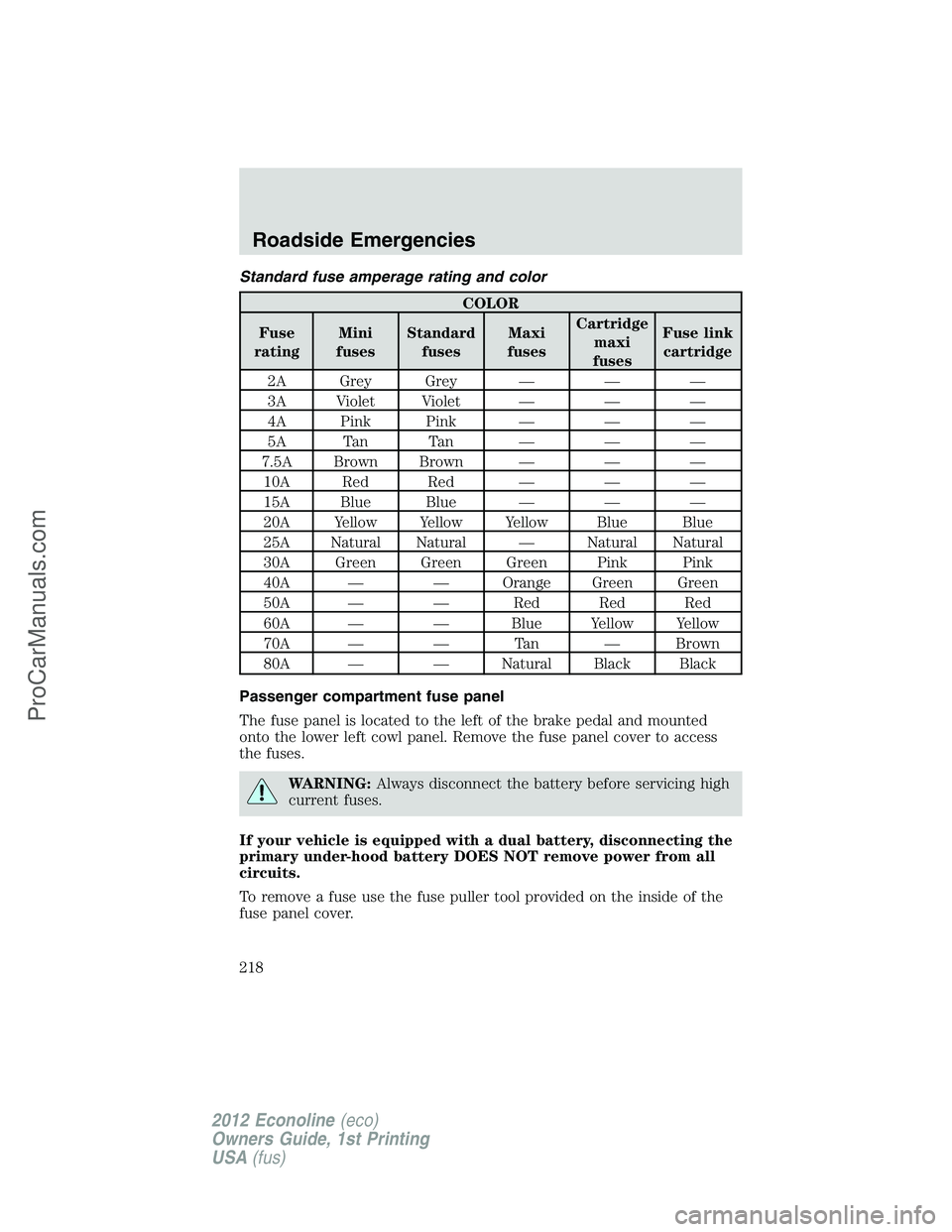
Standard fuse amperage rating and color
COLOR
Fuse
ratingMini
fusesStandard
fusesMaxi
fusesCartridge
maxi
fusesFuse link
cartridge
2A Grey Grey — — —
3A Violet Violet — — —
4A Pink Pink — — —
5A Tan Tan — — —
7.5A Brown Brown — — —
10A Red Red — — —
15A Blue Blue — — —
20A Yellow Yellow Yellow Blue Blue
25A Natural Natural — Natural Natural
30A Green Green Green Pink Pink
40A — — Orange Green Green
50A — — Red Red Red
60A — — Blue Yellow Yellow
70A — — Tan — Brown
80A — — Natural Black Black
Passenger compartment fuse panel
The fuse panel is located to the left of the brake pedal and mounted
onto the lower left cowl panel. Remove the fuse panel cover to access
the fuses.
WARNING:Always disconnect the battery before servicing high
current fuses.
If your vehicle is equipped with a dual battery, disconnecting the
primary under-hood battery DOES NOT remove power from all
circuits.
To remove a fuse use the fuse puller tool provided on the inside of the
fuse panel cover.
Roadside Emergencies
218
2012 Econoline(eco)
Owners Guide, 1st Printing
USA(fus)
ProCarManuals.com
Page 219 of 335
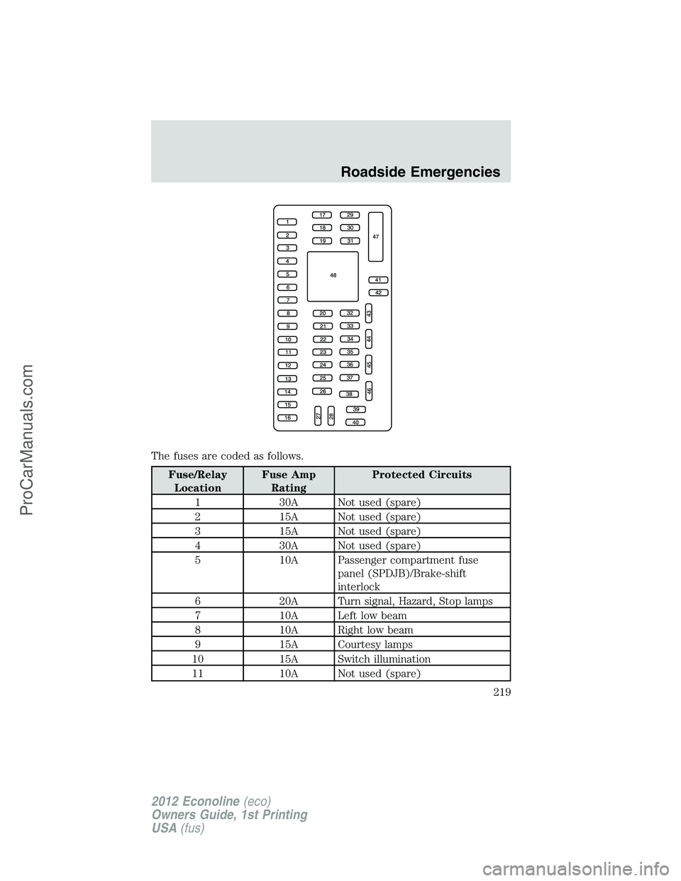
The fuses are coded as follows.
Fuse/Relay
LocationFuse Amp
RatingProtected Circuits
1 30A Not used (spare)
2 15A Not used (spare)
3 15A Not used (spare)
4 30A Not used (spare)
5 10A Passenger compartment fuse
panel (SPDJB)/Brake-shift
interlock
6 20A Turn signal, Hazard, Stop lamps
7 10A Left low beam
8 10A Right low beam
9 15A Courtesy lamps
10 15A Switch illumination
11 10A Not used (spare)
Roadside Emergencies
219
2012 Econoline(eco)
Owners Guide, 1st Printing
USA(fus)
ProCarManuals.com
Page 222 of 335
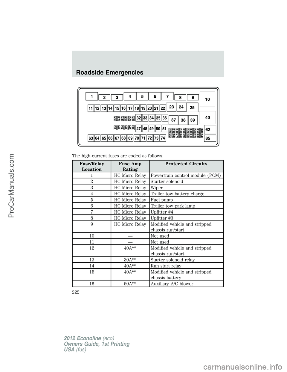
The high-current fuses are coded as follows.
Fuse/Relay
LocationFuse Amp
RatingProtected Circuits
1 HC Micro Relay Powertrain control module (PCM)
2 HC Micro Relay Starter solenoid
3 HC Micro Relay Wiper
4 HC Micro Relay Trailer tow battery charge
5 HC Micro Relay Fuel pump
6 HC Micro Relay Trailer tow park lamp
7 HC Micro Relay Upfitter #4
8 HC Micro Relay Upfitter #3
9 HC Micro Relay Modified vehicle and stripped
chassis run/start
10 — Not used
11 — Not used
12 40A** Modified vehicle and stripped
chassis run/start
13 30A** Starter solenoid relay
14 40A** Run start relay
15 40A** Modified vehicle and stripped
chassis battery
16 50A** Auxiliary A/C blower
Roadside Emergencies
222
2012 Econoline(eco)
Owners Guide, 1st Printing
USA(fus)
ProCarManuals.com