ignition switch FORD E-450 2019 Owner's Manual
[x] Cancel search | Manufacturer: FORD, Model Year: 2019, Model line: E-450, Model: FORD E-450 2019Pages: 329, PDF Size: 6.24 MB
Page 87 of 329
•
Incorrect fuel for climatic conditions.
• Incorrect engine oil viscosity for
climactic conditions.
Note: Some vehicles have a lifetime fuel
filter that is integrated with the fuel tank.
Regular maintenance or replacement is not
needed.
Note: If these checks do not help you
correct the concern, have your vehicle
checked as soon as possible.
Noise Emissions Warranty,
Prohibited Tampering Acts and
Maintenance
On January 1, 1978, Federal regulation
became effective governing the noise
emission on trucks over 10,000 lb
(4,536 kg) Gross Vehicle Weight Rating
(GVWR). The preceding statements
concerning prohibited tampering acts and
maintenance, and the noise warranty
found in the Warranty Guide, are
applicable to complete chassis cabs over
10,000 lb (4,536 kg)
GVWR.
CATALYTIC CONVERTER WARNING:
Do not park, idle or
drive your vehicle on dry grass or other
dry ground cover. The emission system
heats up the engine compartment and
exhaust system, creating the risk of fire. WARNING:
The normal operating
temperature of the exhaust system is
very high. Never work around or attempt
to repair any part of the exhaust system
until it has cooled. Use special care when
working around the catalytic converter.
The catalytic converter heats up to a very
high temperature after only a short
period of engine operation and stays hot
after the engine is switched off. WARNING:
Exhaust leaks may
result in entry of harmful and potentially
lethal fumes into the passenger
compartment. If you smell exhaust
fumes inside your vehicle, have your
vehicle inspected immediately. Do not
drive if you smell exhaust fumes.
Your vehicle has various emission control
components and a catalytic converter that
enables it to comply with applicable
exhaust emission standards.
To make sure that the catalytic converter
and other emission control components
continue to work properly:
• Do not crank the engine for more than
10 seconds at a time.
• Do not run the engine with a spark plug
lead disconnected.
• Do not push-start or tow-start your
vehicle. Use booster cables. See Jump
Starting the Vehicle
(page 121).
• Use only the specified fuel listed.
• Do not switch the ignition off when your
vehicle is moving.
• Avoid running out of fuel.
• Have the items listed in scheduled
maintenance information performed
according to the specified schedule.
Note: Resulting component damage may
not be covered by the vehicle Warranty.
The scheduled maintenance items listed
in scheduled maintenance information are
essential to the life and performance of
your vehicle and to its emissions system.
If you use anything other than Ford,
Motorcraft or Ford-authorized parts for
maintenance replacements or for service
of components affecting emission control,
such non-Ford parts should be equivalent
to genuine Ford Motor Company parts in
performance and durability.
84
E-Series (TE4) Canada/United States of America, enUSA, Edition date: 201804, Second-Printing Engine Emission Control
Page 90 of 329
AUTOMATIC TRANSMISSION
WARNING: Always fully apply the
parking brake. Make sure you shift into
park (P) for vehicles with an automatic
transmission. Switch the ignition off and
remove the key whenever you leave your
vehicle. Putting your vehicle in or out of
gear:
1. Fully press down the brake pedal.
2. Move the gearshift lever into the
desired gear.
3. When you are finished driving, come to
a complete stop.
4. Move the gearshift lever and securely latch it in park (P).
Park (P)
This position locks the transmission and
prevents the wheels from turning.
Reverse (R)
With the transmission in reverse (R), your
vehicle moves backward. Always come to
a complete stop before shifting into and
out of reverse (R). Neutral (N)
With the transmission in neutral (N), you
can start your vehicle and it is free to roll.
Hold the brake pedal down when in this
position.
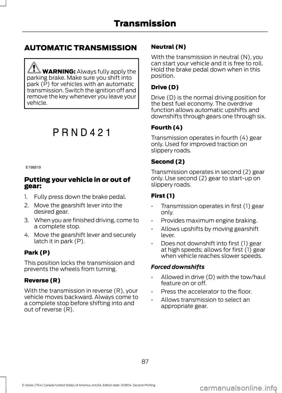
Drive (D)
Drive (D) is the normal driving position for
the best fuel economy. The overdrive
function allows automatic upshifts and
downshifts through gears one through six.
Fourth (4)
Transmission operates in fourth (4) gear
only. Used for improved traction on
slippery roads.
Second (2)
Transmission operates in second (2) gear
only. Use second (2) gear to start-up on
slippery roads.
First (1)
•
Transmission operates in first (1) gear
only.
• Provides maximum engine braking.
• Allows upshifts by moving gearshift
lever.
• Does not downshift into first (1) gear
at high speeds; allows for first (1) gear
when vehicle reaches slower speeds.
Forced downshifts
• Allowed in drive (D) with the tow/haul
feature on or off.
• Press the accelerator to the floor.
• Allows transmission to select an
appropriate gear.
87
E-Series (TE4) Canada/United States of America, enUSA, Edition date: 201804, Second-Printing TransmissionE198819
Page 94 of 329
GENERAL INFORMATION
Note:
Occasional brake noise is normal. If
a metal-to-metal, continuous grinding or
continuous squeal sound is present, the
brake linings may be worn-out and should
be inspected by an authorized dealer. If the
vehicle has continuous vibration or shudder
in the steering wheel while braking, the
vehicle should be inspected by an
authorized dealer.
Note: Brake dust may accumulate on the
wheels, even under normal driving
conditions. Some dust is inevitable as the
brakes wear and does not contribute to
brake noise. See Cleaning the Wheels
(page 165).
Note: Indicators vary depending on region. See
Warning Lamps and
Indicators (page 54). Wet brakes result in reduced braking
efficiency. Gently press the brake pedal a
few times when driving from a car wash or
standing water to dry the brakes.
Brake Over Accelerator
In the event the accelerator pedal
becomes stuck or entrapped, apply steady
and firm pressure to the brake pedal to
slow the vehicle and reduce engine power.
If you experience this condition, apply the
brakes and bring your vehicle to a safe
stop. Switch the engine off, shift the
transmission into park (P), apply the
parking brake, and then inspect the
accelerator pedal for any interferences. If
none are found and the condition persists,
have your vehicle towed to the nearest
authorized dealer. Hydraulic brake booster system
(Hydroboost or Hydromax)
The Hydroboost and Hydromax systems
receive fluid pressure from the power
steering pump to provide power assist
during braking.
The Hydromax booster receives backup
pressure from the reserve system electric
pump whenever the fluid in the power
steering system is not flowing. When the
engine is off, the pump turns on if you apply
the brake pedal, or if you switch the ignition
to the on position.
The sound of the pump operating may be
heard by the driver. This is a normal
characteristic of the system.
The reserve system provides reduced
braking power, so the vehicle should be
operated under these conditions with
caution, and only to seek service repair and
removal of the vehicle from the roadway.
Note:
For vehicles with the Hydromax
system operating under normal conditions,
the noise of the fluid flowing through the
booster may be heard whenever you apply
the brake. This condition is normal. Vehicle
service is not required.
If braking performance or pedal response
becomes very poor, even when you
strongly press the pedal, it may indicate
the presence of air in the hydraulic system
or leakage of fluid. Stop the vehicle safely
as soon as possible and seek service
immediately.
HINTS ON DRIVING WITH
ANTI-LOCK BRAKES
The anti-lock braking system does not
eliminate the risks when:
• You drive too closely to the vehicle in
front of you.
• Your vehicle is hydroplaning.
91
E-Series (TE4) Canada/United States of America, enUSA, Edition date: 201804, Second-Printing BrakesE144522
Page 95 of 329
•
You take corners too fast.
• The road surface is poor.
Note: If the system activates, the brake
pedal may pulse and may travel further.
Maintain pressure on the brake pedal. You
may also hear a noise from the system. This
is normal.
PARKING BRAKE WARNING: Always fully apply the
parking brake. Make sure you shift into
park (P) for vehicles with an automatic
transmission. Switch the ignition off and
remove the key whenever you leave your
vehicle.
Apply the parking brake whenever you park
your vehicle.
• For vehicles with a foot operated
parking brake, press the pedal down.
• For vehicles with a hand operated
parking brake, pull the parking brake
lever up. It illuminates when you switch
the ignition on and apply the
parking brake. It also illuminates
momentarily when you switch
the ignition on to confirm the
lamp is functional. if is does not
illuminate when you switch the ignition on
or begins to flash at any time, have the
system checked by an authorized dealer.
If it illuminates when your vehicle is
moving, make sure you disengage the
parking brake.
If the parking brake is disengaged, this
indicates a low brake fluid level or a brake
system fault. Have your vehicle checked
as soon as possible. To release the parking brake:
•
For vehicles with a foot operated
parking brake, pull the parking brake
release lever.
• For vehicles with a hand operated
parking brake, push the parking brake
lever down.
92
E-Series (TE4) Canada/United States of America, enUSA, Edition date: 201804, Second-Printing BrakesE144522
Page 96 of 329
PRINCIPLE OF OPERATION
The traction control system helps avoid
drive wheel spin and loss of traction.
If your vehicle begins to slide, the system
applies the brakes to individual wheels
and, when needed, reduces engine power
at the same time. If the wheels spin when
accelerating on slippery or loose surfaces,
the system reduces engine power in order
to increase traction.
USING TRACTION CONTROL
WARNING: The traction control
light illuminates steadily if a failure is
detected in the system. Verify that the
traction control system was not
manually disabled using the switch. If
the traction control light is still
illuminating steadily, have the system
serviced by an authorized dealer
immediately. Operating your vehicle with
traction control disabled could lead to
an increased risk of loss of vehicle
control, vehicle rollover, personal injury
and death.
The system automatically turns on each
time you switch the ignition on.
If your vehicle is stuck in mud or snow,
switching traction control off may be
beneficial as this allows the wheels to spin.
Switching the System Off The switch for the traction
control system is located on the
instrument panel.
When you switch the system off, an
illuminated icon appears on the instrument
cluster.
Use the switch again to return the traction
control system to normal operation. System Indicator Lights and
Messages The traction control light
temporarily illuminates on
engine start-up and flashes
when a driving condition activates the
system. The traction control off light
temporarily illuminates on
engine start-up and stays on:
• When you switch the traction control
system off.
• If a problem occurs in the system.
93
E-Series (TE4) Canada/United States of America, enUSA, Edition date: 201804, Second-Printing Traction Control
(If Equipped)E194301 E138639 E194301
Page 100 of 329
Canceling the Set Speed
Tap the brake pedal to cancel the set
speed.
Note:
The system remembers the set
speed.
Resuming the Set Speed Press and release to resume the
set speed.
Switching Cruise Control Off Press and release when the
system is in standby mode, or
switch the ignition off.
Note: You erase the set speed when you
switch the system off.
97
E-Series (TE4) Canada/United States of America, enUSA, Edition date: 201804, Second-Printing Cruise Control (If Equipped) E265297
Page 114 of 329
When used properly, the trailer brake
controller assists in smooth and effective
trailer braking by powering the trailer
’s
electric or electric-over-hydraulic brakes
with a proportional output based on the
towing vehicle ’s brake pressure.
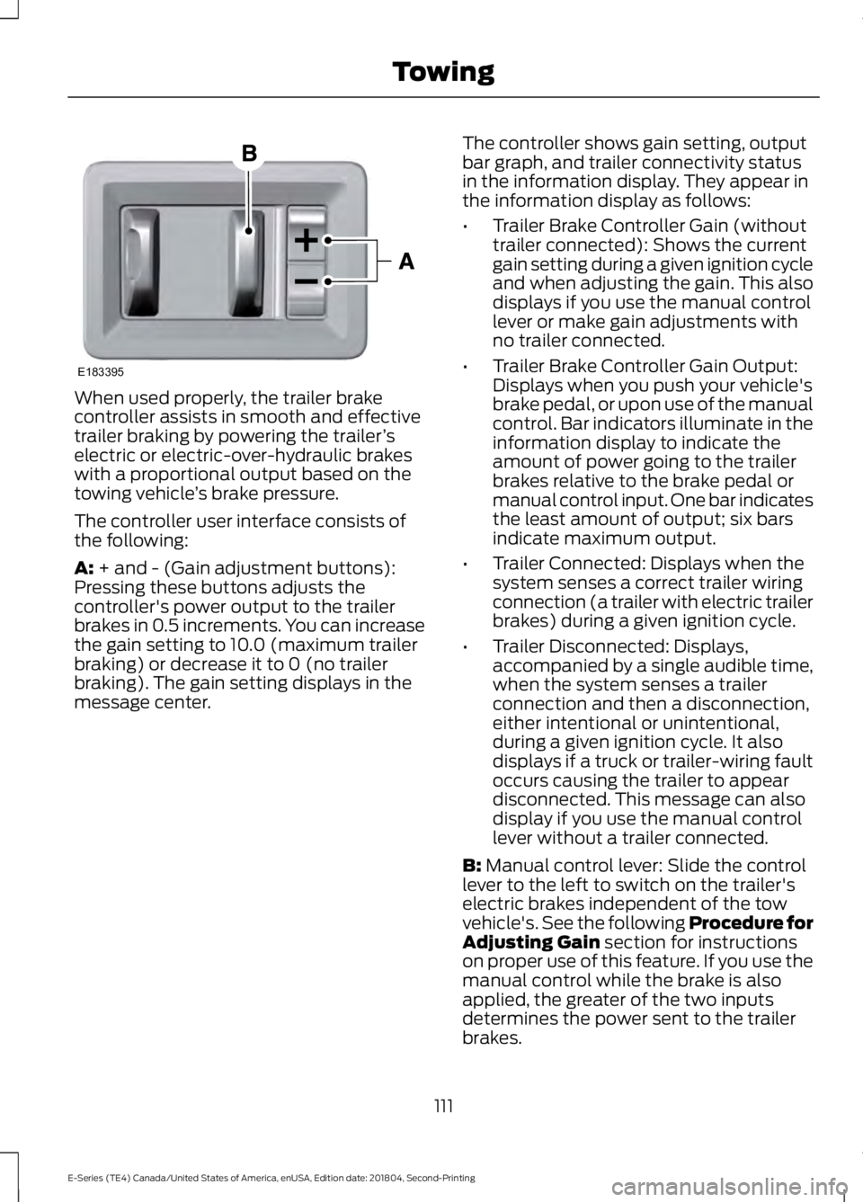
The controller user interface consists of
the following:
A: + and - (Gain adjustment buttons):
Pressing these buttons adjusts the
controller's power output to the trailer
brakes in 0.5 increments. You can increase
the gain setting to 10.0 (maximum trailer
braking) or decrease it to 0 (no trailer
braking). The gain setting displays in the
message center. The controller shows gain setting, output
bar graph, and trailer connectivity status
in the information display. They appear in
the information display as follows:
•
Trailer Brake Controller Gain (without
trailer connected): Shows the current
gain setting during a given ignition cycle
and when adjusting the gain. This also
displays if you use the manual control
lever or make gain adjustments with
no trailer connected.
• Trailer Brake Controller Gain Output:
Displays when you push your vehicle's
brake pedal, or upon use of the manual
control. Bar indicators illuminate in the
information display to indicate the
amount of power going to the trailer
brakes relative to the brake pedal or
manual control input. One bar indicates
the least amount of output; six bars
indicate maximum output.
• Trailer Connected: Displays when the
system senses a correct trailer wiring
connection (a trailer with electric trailer
brakes) during a given ignition cycle.
• Trailer Disconnected: Displays,
accompanied by a single audible time,
when the system senses a trailer
connection and then a disconnection,
either intentional or unintentional,
during a given ignition cycle. It also
displays if a truck or trailer-wiring fault
occurs causing the trailer to appear
disconnected. This message can also
display if you use the manual control
lever without a trailer connected.
B:
Manual control lever: Slide the control
lever to the left to switch on the trailer's
electric brakes independent of the tow
vehicle's. See the following Procedure for
Adjusting Gain
section for instructions
on proper use of this feature. If you use the
manual control while the brake is also
applied, the greater of the two inputs
determines the power sent to the trailer
brakes.
111
E-Series (TE4) Canada/United States of America, enUSA, Edition date: 201804, Second-Printing TowingE183395
Page 116 of 329
Points to Remember
Note:
Do not attempt removal of the trailer
brake controller without consulting the
Workshop Manual. Damage to the unit may
result.
• Adjust gain setting before using the
trailer brake controller for the first time.
• Adjust gain setting, using the procedure
above, whenever road, weather and
trailer or vehicle loading conditions
change from when the gain was initially
set.
• Only use the manual control lever for
proper adjustment of the gain during
trailer setup. Misuse, such as
application during trailer sway, could
cause instability of trailer or tow
vehicle.
• Avoid towing in adverse weather
conditions. The trailer brake controller
does not provide anti-lock control of
the trailer wheels. Trailer wheels can
lock up on slippery surfaces, resulting
in reduced stability of trailer and tow
vehicle.
• The trailer brake controller is equipped
with a feature that reduces output at
vehicle speeds below 11 mph (18 km/h)
so trailer and vehicle braking is not jerky
or harsh. This feature is only available
when applying the brakes using your
vehicle's brake pedal, not the
controller.
• The controller interacts with the brake
control system and powertrain control
system of your vehicle to provide the
best performance on different road
conditions.
• Your vehicle's brake system and the
trailer brake system work
independently of each other. Changing
the gain setting on the controller does
not affect the operation of your
vehicle's brakes whether you attach a
trailer or not. •
When you switch the engine off, the
controller output is disabled and the
display and module shut down. The
controller module and display turn on
when you switch the ignition on.
• The trailer brake controller is only a
factory-installed or dealer-installed
item. Ford is not responsible for
warranty or performance of the
controller due to misuse or customer
installation.
Trailer Lamps WARNING: Never connect any
trailer lamp wiring to the vehicle's tail
lamp wiring; this may damage the
electrical system resulting in fire. Contact
your authorized dealer as soon as
possible for assistance in proper trailer
tow wiring installation. Additional
electrical equipment may be required.
Trailer lamps are required on most towed
vehicles. Make sure all running lights, brake
lights, direction indicators and hazard lights
are working.
Before Towing a Trailer
Practice turning, stopping and backing up
to get the feel of your vehicle-trailer
combination before starting on a trip.
When turning, make wider turns so the
trailer wheels clear curbs and other
obstacles.
When Towing a Trailer
• Do not drive faster than
70 mph
(113 km/h) during the first 500 mi
(800 km).
• Do not make full-throttle starts.
• Check your hitch, electrical connections
and trailer wheel lug nuts thoroughly
after you have traveled 50 mi (80 km).
113
E-Series (TE4) Canada/United States of America, enUSA, Edition date: 201804, Second-Printing Towing
Page 136 of 329
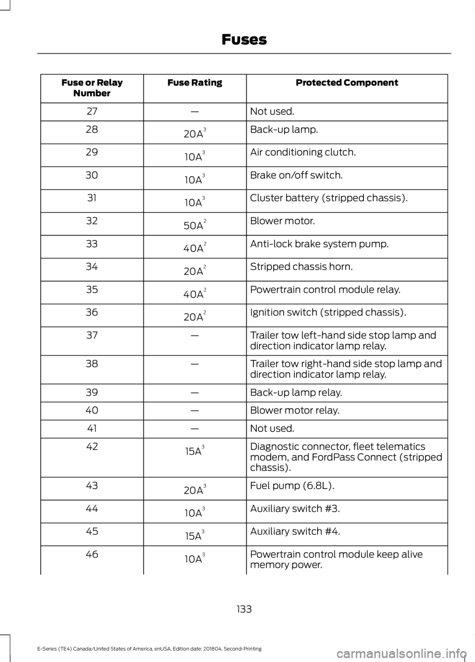
Protected Component
Fuse Rating
Fuse or Relay
Number
Not used.
—
27
Back-up lamp.
20A 3
28
Air conditioning clutch.
10A 3
29
Brake on/off switch.
10A 3
30
Cluster battery (stripped chassis).
10A 3
31
Blower motor.
50A 2
32
Anti-lock brake system pump.
40A 2
33
Stripped chassis horn.
20A 2
34
Powertrain control module relay.
40A 2
35
Ignition switch (stripped chassis).
20A 2
36
Trailer tow left-hand side stop lamp and
direction indicator lamp relay.
—
37
Trailer tow right-hand side stop lamp and
direction indicator lamp relay.
—
38
Back-up lamp relay.
—
39
Blower motor relay.
—
40
Not used.
—
41
Diagnostic connector, fleet telematics
modem, and FordPass Connect (stripped
chassis).
15A
3
42
Fuel pump (6.8L).
20A 3
43
Auxiliary switch #3.
10A 3
44
Auxiliary switch #4.
15A 3
45
Powertrain control module keep alive
memory power.
10A 3
46
133
E-Series (TE4) Canada/United States of America, enUSA, Edition date: 201804, Second-Printing Fuses
Page 141 of 329
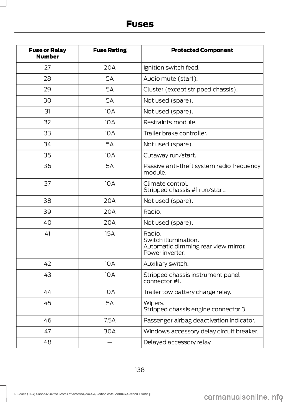
Protected Component
Fuse Rating
Fuse or Relay
Number
Ignition switch feed.
20A
27
Audio mute (start).
5A
28
Cluster (except stripped chassis).
5A
29
Not used (spare).
5A
30
Not used (spare).
10A
31
Restraints module.
10A
32
Trailer brake controller.
10A
33
Not used (spare).
5A
34
Cutaway run/start.
10A
35
Passive anti-theft system radio frequency
module.
5A
36
Climate control.
10A
37
Stripped chassis #1 run/start.
Not used (spare).
20A
38
Radio.
20A
39
Not used (spare).
20A
40
Radio.
15A
41
Switch illumination.
Automatic dimming rear view mirror.
Power inverter.
Auxiliary switch.
10A
42
Stripped chassis instrument panel
connector #1.
10A
43
Trailer tow battery charge relay.
10A
44
Wipers.
5A
45
Stripped chassis engine connector 3.
Passenger airbag deactivation indicator.
7.5A
46
Windows accessory delay circuit breaker.
30A
47
Delayed accessory relay.
—
48
138
E-Series (TE4) Canada/United States of America, enUSA, Edition date: 201804, Second-Printing Fuses