engine FORD E SERIES 1998 4.G Owner's Manual
[x] Cancel search | Manufacturer: FORD, Model Year: 1998, Model line: E SERIES, Model: FORD E SERIES 1998 4.GPages: 144, PDF Size: 2.14 MB
Page 74 of 144
Your vehicle's load capacity is designated by weight, not by volume, so
you cannot necessarily use all available space when loading a vehicle.
Distribute the load so that only 10 to 15% of the total is on the tongue.
Tie down the load so that it does not shift and change the weight on the
hitch.
Towing a trailer places an additional load on your vehicle's engine,
transmission, axle, brakes, tires and suspension. Inspect these
components carefully after any towing operation.
Do not exceed the GVWR or the GAWR specified on the Safety
Compliance Certification Label.
Towing trailers beyond the maximum recommended gross trailer
weight could result in engine damage, transmission/axle damage,
structural damage, loss of control, and personal injury.
Preparing to tow
Use the proper equipment for towing a trailer, and make sure it is
properly attached to your vehicle. See your dealer or a reliable trailer
dealer if you require assistance.
Hitches
Do not use or install hitches that clamp onto the bumper or to the axle.
Underbody hitches are acceptable if installed properly.
Safety chains
Always connect the trailer's safety chains to the vehicle. To connect the
trailer's safety chains, cross the chains under the trailer tongue and allow
slack for turning corners.
If you use a rental trailer, follow the instructions that the rental agency
gives to you.
Trailer brakes
Electric brakes and manual, automatic or surge-type brakes are safe if
installed properly and adjusted to the manufacturer's specifications. The
trailer brakes must meet local and Federal regulations.
Do not connect a trailer's hydraulic brake system directly to your
vehicle's brake system. Your vehicle may not have enough
braking power and your chances of having a collision greatly increase.
Driving
74
Page 75 of 144

The braking system of the tow vehicle is rated for operation at the
GVWR not GCWR.
Trailer lamps
Trailer lamps are required on most towed vehicles. Make sure your
trailer lamps conform to local and Federal regulations. See your dealer or
trailer rental agency for proper instructions and equipment for hooking
up trailer lamps.
Using a step bumper
The rear bumper is equipped with an integral hitch and requires only a
ball with a 25.4 mm (one inch) shank diameter. The bumper hasa2270
kg (5 000 lb.) trailer weight and 227 kg (500 lb.) tongue weight
capability.
If it is necessary to relocate the trailer hitch ball position, a
frame-mounted trailer hitch must be installed.
Driving while you tow
Do not drive faster than 88 km/h (55 mph) when towing a trailer. Do not
drive faster than 72 km/h (45 mph) with any weight on the trailer while
towing on a hot day or in hilly country.
Speed control may shut off if you are towing on long, steep grades.
When towing a trailer:
²Use D (Drive) or a lower gear when towing up or down steep hills.
This will eliminate excessive downshifting and upshifting for optimum
fuel economy and transmission cooling.
²Anticipate stops and brake gradually.
When descending long, steep downhill grades, always use a lower gear to
provide engine braking to save wear on brakes. Use Drive (Overdrive
OFF) on moderately steep hills, Second (2) on steep hills, and First (1)
on very steep hills.
Servicing after towing
If you tow a trailer for long distances, your vehicle will require more
frequent service intervals. Refer to the Severe Duty Schedule in your
ªService Guideº for more information.
Driving
75
Page 76 of 144
Trailer towing tips
²Practice turning, stopping and backing up in an area before starting on
a trip to get the feel of the vehicle trailer combination. When turning,
make wider turns so the trailer wheels will clear curbs and other
obstacles.
²Allow more distance for stopping with a trailer attached.
²The trailer tongue weight should be 10±15% of the loaded trailer
weight.
²After you have traveled 80 km (50 miles), thoroughly check your
hitch, electrical connections and trailer wheel lug nuts.
²When stopped in traffic for long periods of time in hot weather, place
the gearshift in P (Park) and increase idle speed. This aids engine
cooling and air conditioner efficiency.
²Vehicles with trailers should not be parked on a grade. If you must
park on a grade, place wheel chocks under the trailer's wheels.
Launching or retrieving a boat
When backing down a ramp during boat launching or retrieval,
²Do not allow the static water level to rise above the bottom edge of
the rear bumper and
²Do not allow waves to break higher than 15 cm (six inches) above the
bottom edge of the rear bumper.
Exceeding these limits may allow water to enter critical vehicle
components, adversely affecting driveability, emissions and reliability.
If the rear axle is submerged in water, the rear axle lubricant should be
changed. Axle lubricant quantities are not to be checked unless a leak is
suspected.
FUEL CONSUMPTION
Fuel economy can be improved by avoiding:
²lack of regular, scheduled maintenance.
²excessive speed.
²rapid acceleration.
²extended idle.
Driving
76
Page 77 of 144
HAZARD LIGHTS CONTROL
Use only in an emergency to warn traffic of vehicle breakdown,
approaching danger, etc. The hazard flashers can be operated when the
ignition is off.
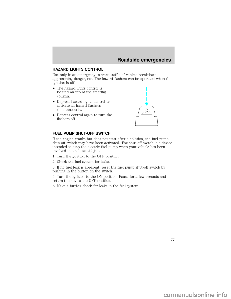
²The hazard lights control is
located on top of the steering
column.
²Depress hazard lights control to
activate all hazard flashers
simultaneously.
²Depress control again to turn the
flashers off.
FUEL PUMP SHUT-OFF SWITCH
If the engine cranks but does not start after a collision, the fuel pump
shut-off switch may have been activated. The shut-off switch is a device
intended to stop the electric fuel pump when your vehicle has been
involved in a substantial jolt.
1. Turn the ignition to the OFF position.
2. Check the fuel system for leaks.
3. If no fuel leak is apparent, reset the fuel pump shut-off switch by
pushing in the button on the switch.
4. Turn the ignition to the ON position. Pause for a few seconds and
return the key to the OFF position.
5. Make a further check for leaks in the fuel system.
Roadside emergencies
77
Page 82 of 144
Fuse/Relay
LocationFuse Amp
RatingDescription
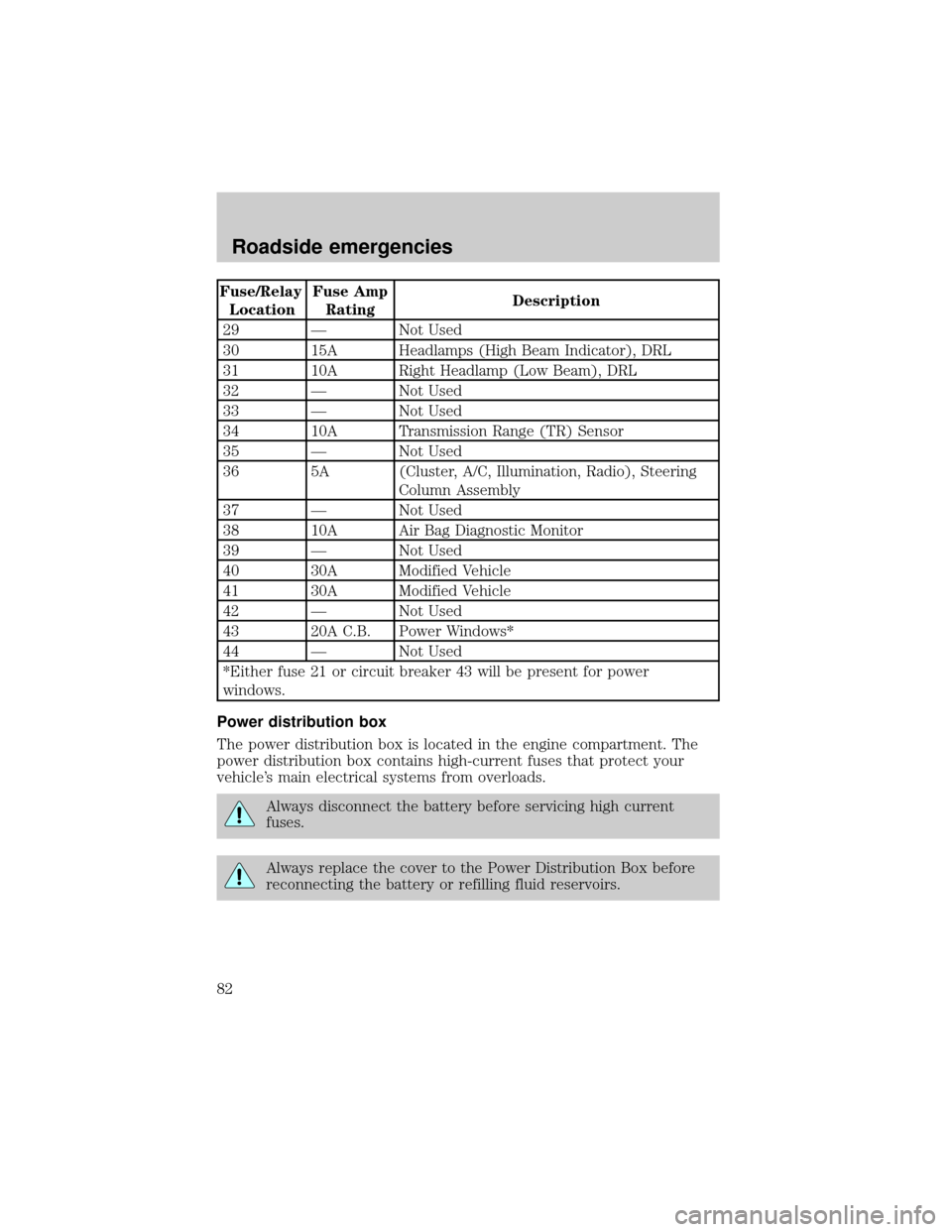
29 Ð Not Used
30 15A Headlamps (High Beam Indicator), DRL
31 10A Right Headlamp (Low Beam), DRL
32 Ð Not Used
33 Ð Not Used
34 10A Transmission Range (TR) Sensor
35 Ð Not Used
36 5A (Cluster, A/C, Illumination, Radio), Steering
Column Assembly
37 Ð Not Used
38 10A Air Bag Diagnostic Monitor
39 Ð Not Used
40 30A Modified Vehicle
41 30A Modified Vehicle
42 Ð Not Used
43 20A C.B. Power Windows*
44 Ð Not Used
*Either fuse 21 or circuit breaker 43 will be present for power
windows.
Power distribution box
The power distribution box is located in the engine compartment. The
power distribution box contains high-current fuses that protect your
vehicle's main electrical systems from overloads.
Always disconnect the battery before servicing high current
fuses.
Always replace the cover to the Power Distribution Box before
reconnecting the battery or refilling fluid reservoirs.
Roadside emergencies
82
Page 83 of 144
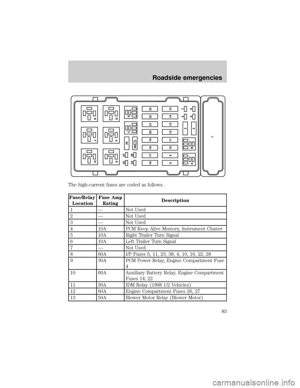
The high-current fuses are coded as follows.
Fuse/Relay
LocationFuse Amp
RatingDescription
1 Ð Not Used
2 Ð Not Used
3 Ð Not Used
4 10A PCM Keep Alive Memory, Instrument Cluster
5 10A Right Trailer Turn Signal
6 10A Left Trailer Turn Signal
7 Ð Not Used
8 60A I/P Fuses 5, 11, 23, 38, 4, 10, 16, 22, 28
9 30A PCM Power Relay, Engine Compartment Fuse
4
10 60A Auxiliary Battery Relay, Engine Compartment
Fuses 14, 22
11 30A IDM Relay (1998 1/2 Vehicles)
12 60A Engine Compartment Fuses 26, 27
13 50A Blower Motor Relay (Blower Motor)
AB3
2
146 5715 14 13 12 11 10 9 823 22 21 20 19 18 17 1624 26 25 27
29
CDG F EK J H
28
Roadside emergencies
83
Page 86 of 144
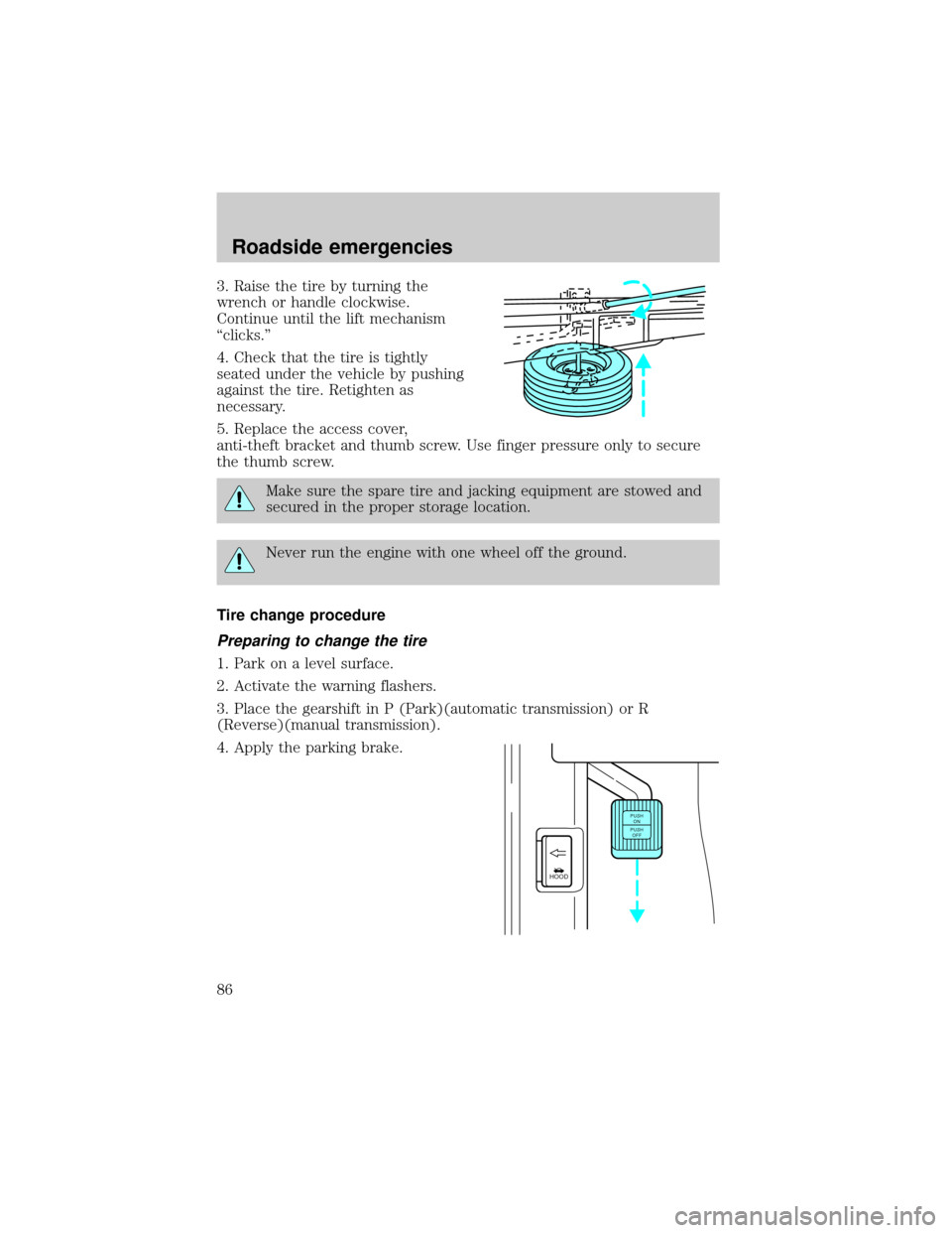
3. Raise the tire by turning the
wrench or handle clockwise.
Continue until the lift mechanism
ªclicks.º
4. Check that the tire is tightly
seated under the vehicle by pushing
against the tire. Retighten as
necessary.
5. Replace the access cover,
anti-theft bracket and thumb screw. Use finger pressure only to secure
the thumb screw.
Make sure the spare tire and jacking equipment are stowed and
secured in the proper storage location.
Never run the engine with one wheel off the ground.
Tire change procedure
Preparing to change the tire
1. Park on a level surface.
2. Activate the warning flashers.
3. Place the gearshift in P (Park)(automatic transmission) or R
(Reverse)(manual transmission).
4. Apply the parking brake.
HOOD
PUSH
ON
PUSH
OFF
Roadside emergencies
86
Page 88 of 144
Replacing the tire
1. Assemble the jack handle sections together and lock into jack. Use the
jack handle to slide the jack under the vehicle.
To lessen the risk of personal injury, do not put any part of your
body under the vehicle while changing a tire. Do not start the
engine when your vehicle is on the jack. The jack is only meant for
changing the tire.
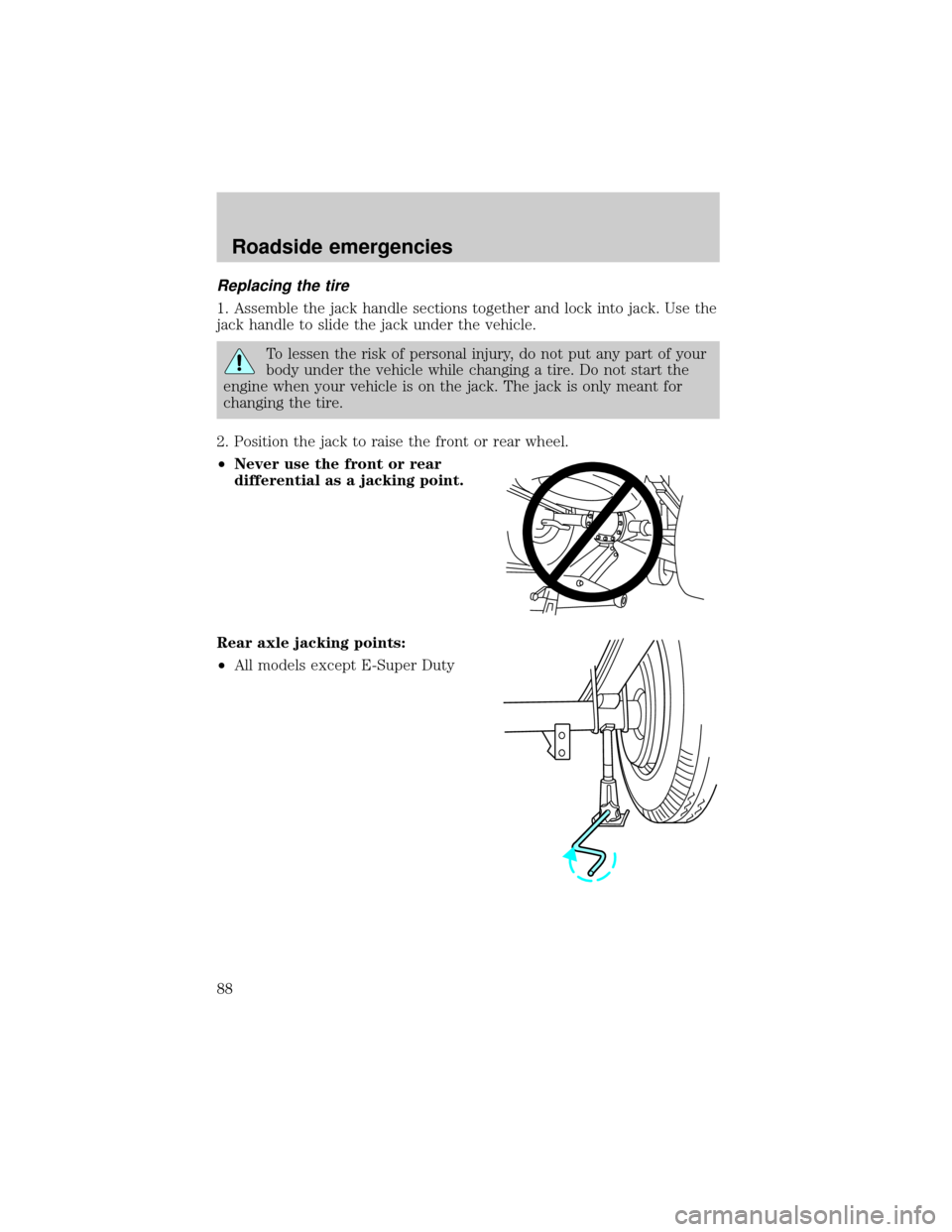
2. Position the jack to raise the front or rear wheel.
²Never use the front or rear
differential as a jacking point.
Rear axle jacking points:
²All models except E-Super Duty
Roadside emergencies
88
Page 91 of 144
Model Bolt Size Wheel Lug nut Torque*
N²M Ft-Lb
E-150 1/2-20 135 100
E-250, E-350 and
E-Super Duty9/16-18 190 140
* Torque specifications are for nut and bolt threads free of dirt and
rust. Do not use oil or grease on threads. Use only Ford recommended
replacement fasteners.
JUMP STARTING YOUR VEHICLE
The gases around the battery can explode if exposed to flames,
sparks, or lit cigarettes. An explosion could result in injury or
vehicle damage.
Do not push start your vehicle. You could damage the catalytic
converter.
Batteries contain sulfuric acid which burns skin, eyes, and
clothing.
Preparing your vehicle
Also see the label on the battery.
1. Use only a 12±volt supply to start your vehicle. If you connect your
battery to a 24±volt power supply you can damage your starter, ignition
system and other electrical components.
2. Do not disconnect the battery of the disabled vehicle as this could
damage the vehicle's electrical system.
3. Park the booster vehicle close to the hood of the disabled vehicle
making sure theydo nottouch. Set the parking brake on both vehicles
and stay clear of the engine cooling fan and other moving parts.
4. Check all battery terminals and remove any excessive corrosion before
you attach the battery cables.
5. Turn the heater fan on in both vehicles to protect any electrical
surges. Turn all other accessories off.
Roadside emergencies
91
Page 92 of 144
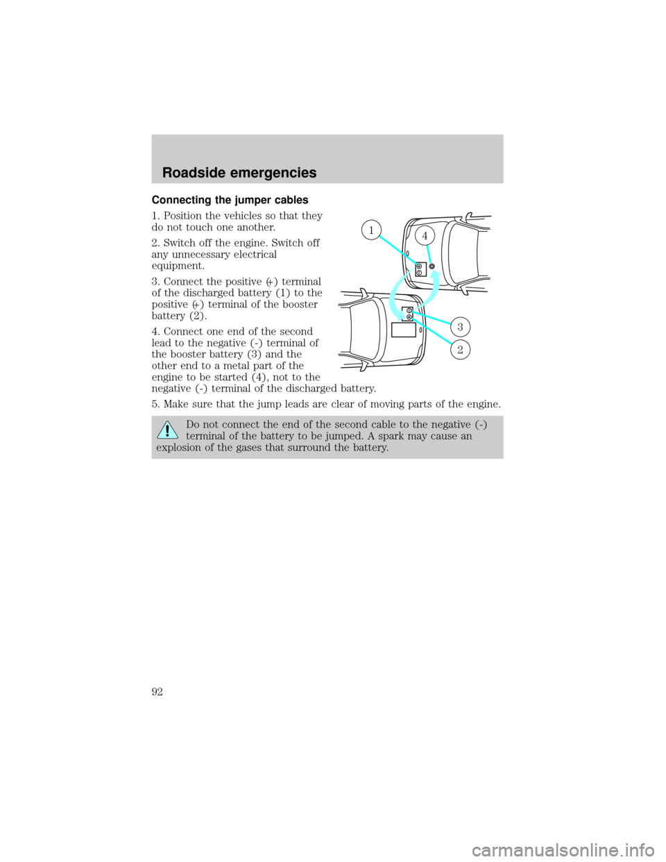
Connecting the jumper cables
1. Position the vehicles so that they
do not touch one another.
2. Switch off the engine. Switch off
any unnecessary electrical
equipment.
3. Connect the positive (+) terminal
of the discharged battery (1) to the
positive (+) terminal of the booster
battery (2).
4. Connect one end of the second
lead to the negative (-) terminal of
the booster battery (3) and the
other end to a metal part of the
engine to be started (4), not to the
negative (-) terminal of the discharged battery.
5. Make sure that the jump leads are clear of moving parts of the engine.
Do not connect the end of the second cable to the negative (-)
terminal of the battery to be jumped. A spark may cause an
explosion of the gases that surround the battery.
+–
+–
14
3
2
Roadside emergencies
92