FORD E SERIES 1999 4.G Owners Manual
Manufacturer: FORD, Model Year: 1999, Model line: E SERIES, Model: FORD E SERIES 1999 4.GPages: 208, PDF Size: 1.93 MB
Page 121 of 208

OFF) on moderately steep hills, Second (2) on steep hills, and First (1)
on very steep hills.
Servicing after towing
If you tow a trailer for long distances, your vehicle will require more
frequent service intervals. Refer to your maintenance guide and or
service guide for more information.
Trailer towing tips
²Practice turning, stopping and backing up in an area before starting on
a trip to get the feel of the vehicle trailer combination. When turning,
make wider turns so the trailer wheels will clear curbs and other
obstacles.
²Allow more distance for stopping with a trailer attached.
²The trailer tongue weight should be 10±15% of the loaded trailer
weight.
²If you will be towing a trailer frequently in hot weather, hilly
conditions, at GCW, or any combination of these factors, consider
refilling your rear axle with synthetic gear lube. Refer to the
Capacities and specificationschapter for the lubricant specification.
²After you have traveled 80 km (50 miles), thoroughly check your
hitch, electrical connections and trailer wheel lug nuts.
²When stopped in traffic for long periods of time in hot weather, place
the gearshift in P (Park) and increase idle speed. This aids engine
cooling and air conditioner efficiency.
²Vehicles with trailers should not be parked on a grade. If you must
park on a grade, place wheel chocks under the trailer's wheels.
Launching or retrieving a boat
When backing down a ramp during boat launching or retrieval,
²Do not allow the static water level to rise above the bottom edge of
the rear bumper and
²Do not allow waves to break higher than 15 cm (six inches) above the
bottom edge of the rear bumper.
Exceeding these limits may allow water to enter critical vehicle
components, adversely affecting driveability, emissions, reliability and
causing internal transmission damage.
Driving
121
Page 122 of 208

Replace the rear axle lubricant anytime the axle has been submerged in
water. Rear axle lubricant quantities are not to be checked or changed
unless a leak is suspected or repair required.
Disconnect the wiring to the trailer before backing the trailer into the
water. Reconnect the wiring to the trailer after the trailer is removed
from the water.
Driving
122
Page 123 of 208
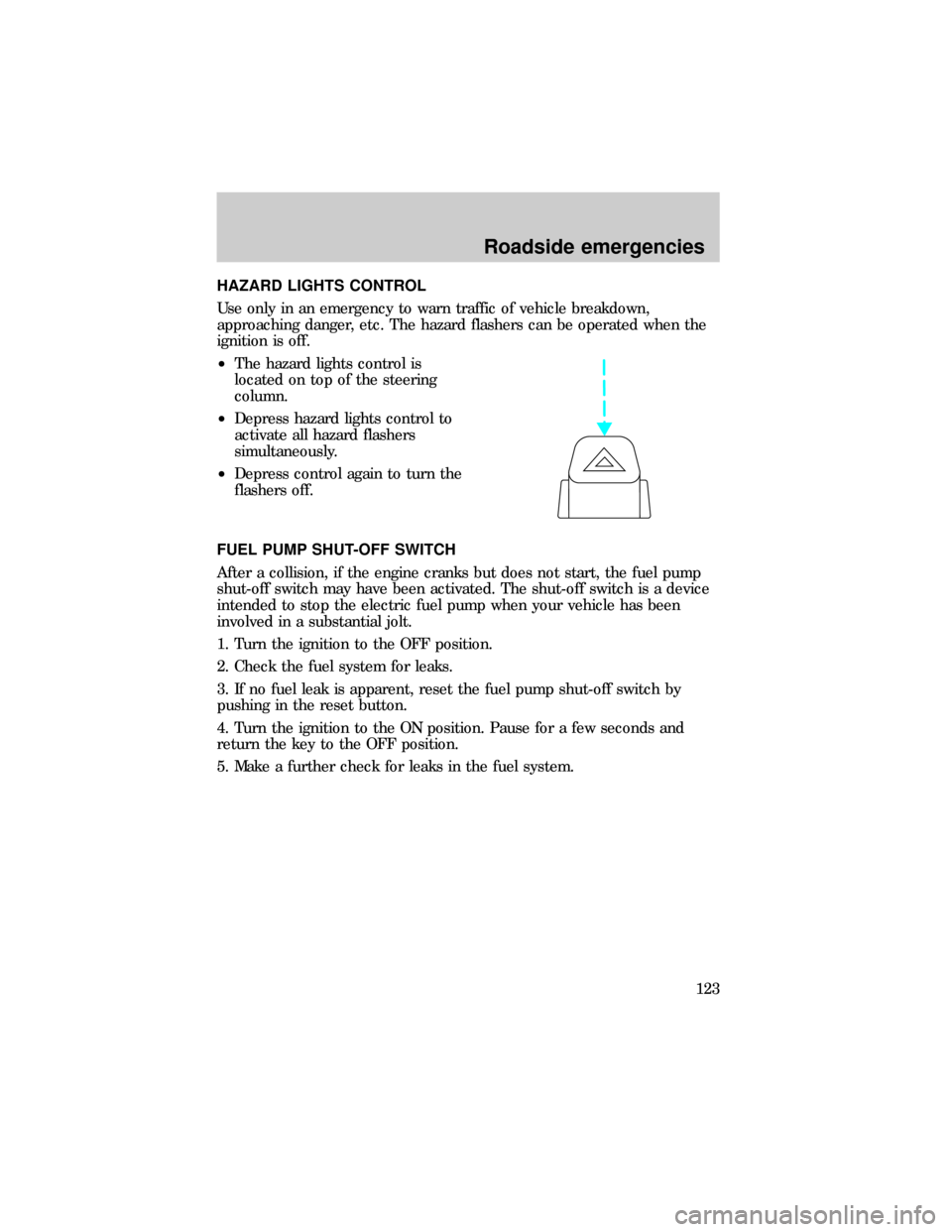
HAZARD LIGHTS CONTROL
Use only in an emergency to warn traffic of vehicle breakdown,
approaching danger, etc. The hazard flashers can be operated when the
ignition is off.
²The hazard lights control is
located on top of the steering
column.
²Depress hazard lights control to
activate all hazard flashers
simultaneously.
²Depress control again to turn the
flashers off.
FUEL PUMP SHUT-OFF SWITCH
After a collision, if the engine cranks but does not start, the fuel pump
shut-off switch may have been activated. The shut-off switch is a device
intended to stop the electric fuel pump when your vehicle has been
involved in a substantial jolt.
1. Turn the ignition to the OFF position.
2. Check the fuel system for leaks.
3. If no fuel leak is apparent, reset the fuel pump shut-off switch by
pushing in the reset button.
4. Turn the ignition to the ON position. Pause for a few seconds and
return the key to the OFF position.
5. Make a further check for leaks in the fuel system.
Roadside emergencies
123
Page 124 of 208
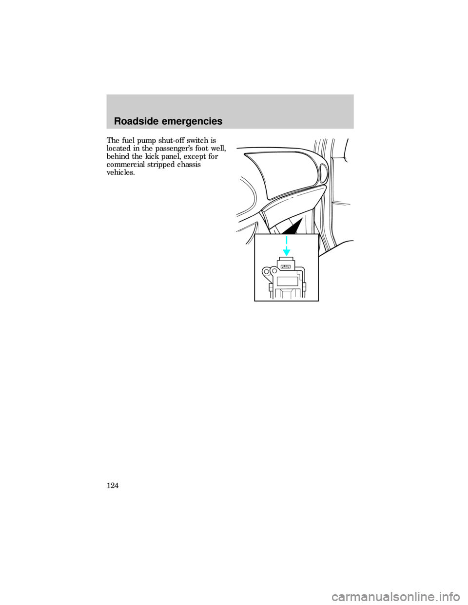
The fuel pump shut-off switch is
located in the passenger's foot well,
behind the kick panel, except for
commercial stripped chassis
vehicles.
Roadside emergencies
124
Page 125 of 208
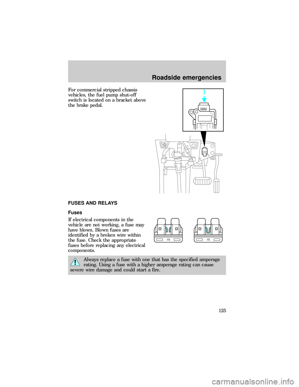
For commercial stripped chassis
vehicles, the fuel pump shut-off
switch is located on a bracket above
the brake pedal.
FUSES AND RELAYS
Fuses
If electrical components in the
vehicle are not working, a fuse may
have blown. Blown fuses are
identified by a broken wire within
the fuse. Check the appropriate
fuses before replacing any electrical
components.
Always replace a fuse with one that has the specified amperage
rating. Using a fuse with a higher amperage rating can cause
severe wire damage and could start a fire.
1515
Roadside emergencies
125
Page 126 of 208
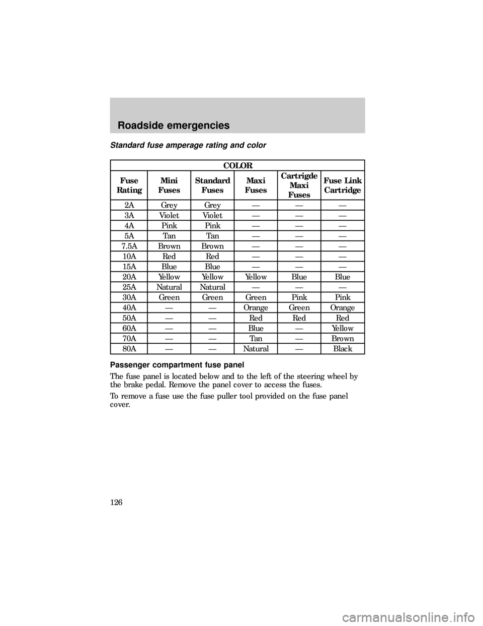
Standard fuse amperage rating and color
COLOR
Fuse
RatingMini
FusesStandard
FusesMaxi
FusesCartrigde
Maxi
FusesFuse Link
Cartridge
2A Grey Grey Ð Ð Ð
3A Violet Violet Ð Ð Ð
4A Pink Pink Ð Ð Ð
5A Tan Tan Ð Ð Ð
7.5A Brown Brown Ð Ð Ð
10A Red Red Ð Ð Ð
15A Blue Blue Ð Ð Ð
20A Yellow Yellow Yellow Blue Blue
25A Natural Natural Ð Ð Ð
30A Green Green Green Pink Pink
40A Ð Ð Orange Green Orange
50A Ð Ð Red Red Red
60A Ð Ð Blue Ð Yellow
70A Ð Ð Tan Ð Brown
80A Ð Ð Natural Ð Black
Passenger compartment fuse panel
The fuse panel is located below and to the left of the steering wheel by
the brake pedal. Remove the panel cover to access the fuses.
To remove a fuse use the fuse puller tool provided on the fuse panel
cover.
Roadside emergencies
126
Page 127 of 208
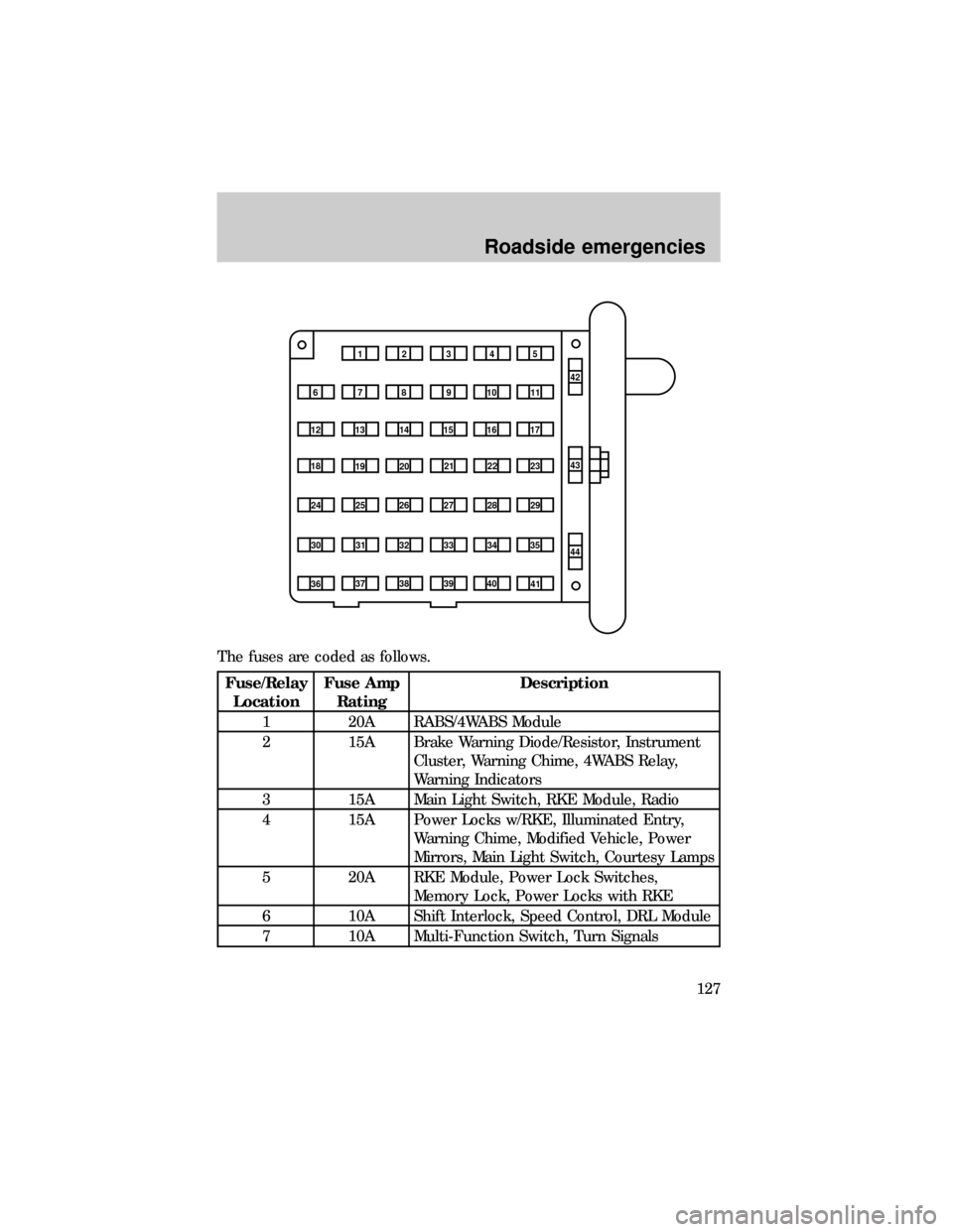
The fuses are coded as follows.
Fuse/Relay
LocationFuse Amp
RatingDescription
1 20A RABS/4WABS Module
2 15A Brake Warning Diode/Resistor, Instrument
Cluster, Warning Chime, 4WABS Relay,
Warning Indicators
3 15A Main Light Switch, RKE Module, Radio
4 15A Power Locks w/RKE, Illuminated Entry,
Warning Chime, Modified Vehicle, Power
Mirrors, Main Light Switch, Courtesy Lamps
5 20A RKE Module, Power Lock Switches,
Memory Lock, Power Locks with RKE
6 10A Shift Interlock, Speed Control, DRL Module
7 10A Multi-Function Switch, Turn Signals
1234
5
7
689101142
43
44 13 12 14
15 16 17
19 18
2021 22 23
25 24
26 27 28 29
31 30 32 33 3435
37
3638 3940
41
Roadside emergencies
127
Page 128 of 208
Fuse/Relay
LocationFuse Amp
RatingDescription
8 30A Radio Capacitor(s), Ignition Coil, PCM
Diode, PCM Power Relay, Fuel Heater,
Glow Plug Relay (Diesel Only)
9 30A Wiper Control Module, Windshield Wiper
Motor
10 20A Main Light Switch, (External Lamps)
Multi-Function Switch (Flash-to-pass)
11 15A Brake Pressure Switch, Multi-Function
Switch (Hazards), RABS, Brake Pedal
Position Switch
12 15A Transmission Range (TR) Sensor, Auxiliary
Battery Relay
13 15A Blend Door Actuator, Function Selector
Switch
14 5A Instrument Cluster (Air Bag and Charge
Indicator)
15 5A Trailer Battery Charge Relay
16 30A Power Seats
17 Ð Not Used
18 Ð Not Used
19 10A Air Bag Diagnostic Monitor
20 5A Overdrive Cancel Switch
21 30A Power Windows*
22 15A Memory Power Radio
23 20A Cigar Lighter, Data Link Connector (DLC)
24 5A Illuminated Entry Module
25 10A Left Headlamp (Low Beam)
26 Ð Not Used
27 5A Radio
28 25A Power Plug
29 Ð Not Used
30 15A Headlamps (High Beam Indicator), DRL10A
Roadside emergencies
128
Page 129 of 208
Fuse/Relay
LocationFuse Amp
RatingDescription
31 10A Right Headlamp (Low Beam), DRL
32 Ð Not Used
33 Ð Not Used
34 10A Transmission Range (TR) Sensor
35 Ð Not Used
36 5A (Cluster, A/C, Illumination, Radio), Steering
Column Assembly
37 Ð Not Used
38 10A Air Bag Diagnostic Monitor
39 Ð Not Used
40 30A Modified Vehicle
41 30A Modified Vehicle
42 Ð Not Used
43 20A C.B. Power Windows*
44 Ð Not Used
* Either fuse 21 or circuit breaker 43 will be present for power
windows.
Power distribution box
The power distribution box is located in the engine compartment. The
power distribution box contains high-current fuses that protect your
vehicle's main electrical systems from overloads.
Always disconnect the battery before servicing high current
fuses.
Always replace the cover to the Power Distribution Box before
reconnecting the battery or refilling fluid reservoirs.
Roadside emergencies
129
Page 130 of 208
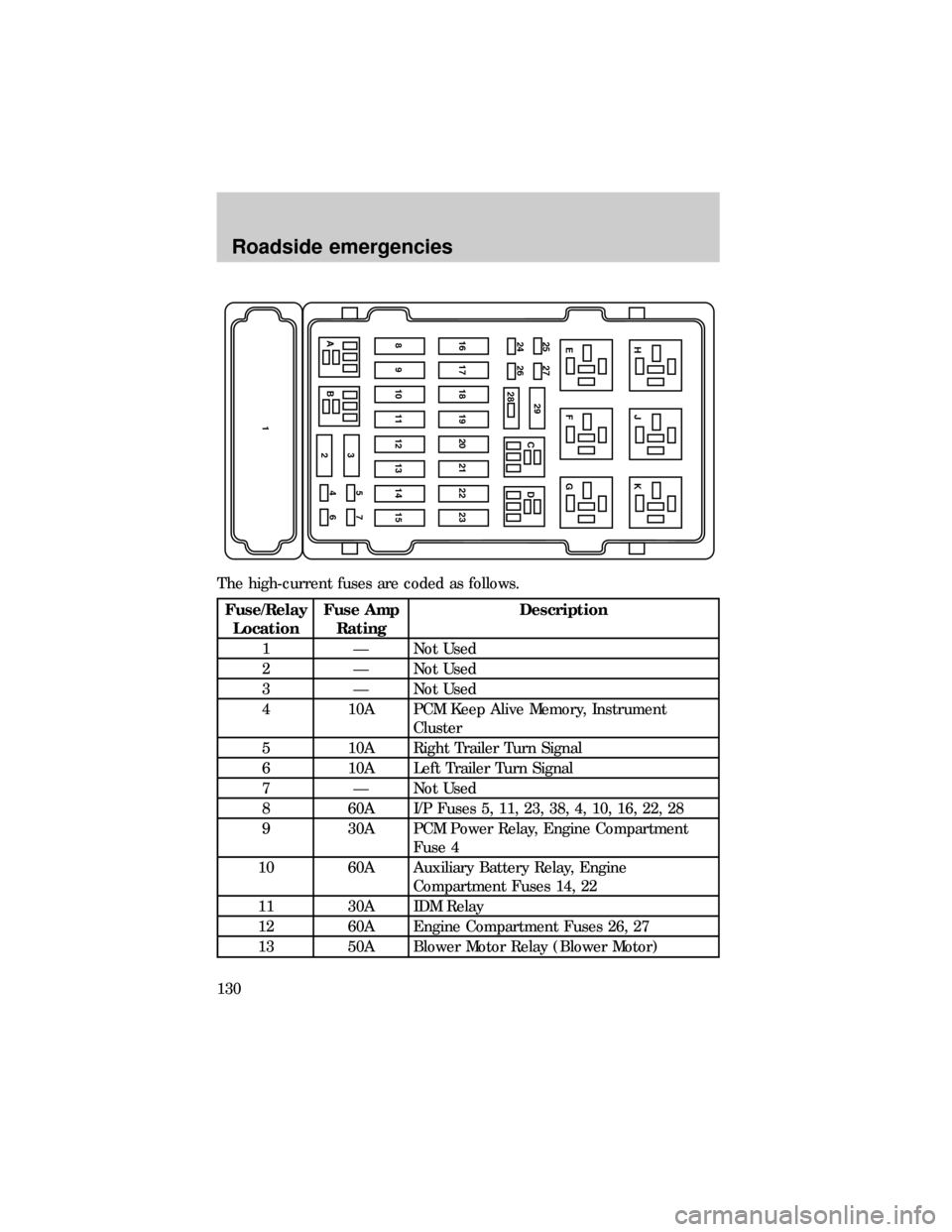
The high-current fuses are coded as follows.
Fuse/Relay
LocationFuse Amp
RatingDescription
1 Ð Not Used
2 Ð Not Used
3 Ð Not Used
4 10A PCM Keep Alive Memory, Instrument
Cluster
5 10A Right Trailer Turn Signal
6 10A Left Trailer Turn Signal
7 Ð Not Used
8 60A I/P Fuses 5, 11, 23, 38, 4, 10, 16, 22, 28
9 30A PCM Power Relay, Engine Compartment
Fuse 4
10 60A Auxiliary Battery Relay, Engine
Compartment Fuses 14, 22
11 30A IDM Relay
12 60A Engine Compartment Fuses 26, 27
13 50A Blower Motor Relay (Blower Motor)
AB3
2
146 5715 14 13 12 11 10 9 823 22 21 20 19 18 17 1624 26 25 27
29
CDG F EK J H
28
Roadside emergencies
130